Eagle CAD
The challenge:
Draw a circuit board. Either redrawing an existing board and adding new functionality. Or creating a new board. Use design rules to check for potential fabrication issues.
Mill and populate the board.
Plan of attack:
Design a board in eagle using the Fab, Sparkfun and Adafruit libraries. Mill, populate then test the board.
Approach:
Use this weeks assignment as an opportunity to develop aspects of my final project. In particular testing sound generation using the speakers and electrical components within the fab inventory.
Jumping into Eagle
A key part of my final project is to be able to reproduce sound at a reasonable quality and in differing orders. To achieve this I drew up a board loosely biased off elec freaks tutorial. It contained a reverse polarity protection fet, 5v regulator for the IC, LED and speaker and a 3.3v regulator driving an SD card via a level conversion circuit. The idea being to store wav files on the SD card, then play them via the speaker attached to the opamp.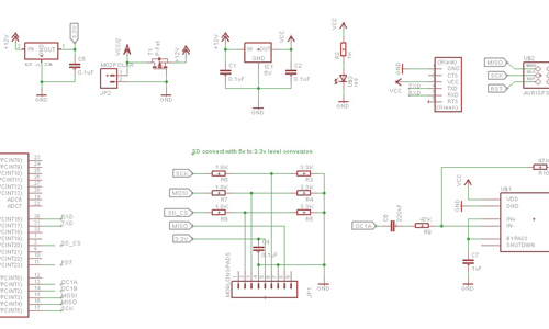
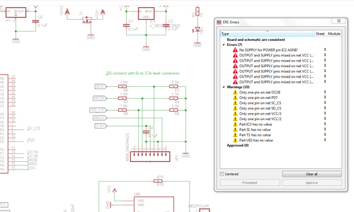
Eagles built in ERC wins again and picked up on a small typo that would have rendered my SD card useless. It also did a good amount of just general complaining that could be safely ignored.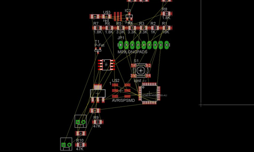
I got this version of the board as far as the layout stage before realising a few issues with it. The resistor values couldn’t be rounded up without breaking the level conversion for the SD card. Meaning it would require upwards of 6 resistors to convert each leg with the values available on hand. Secondly the attiny4X chip weren’t going to have enough memory to support transcoding the wav data to the speaker. The next chip we have that could support it was an atmega328.
Scaling it back
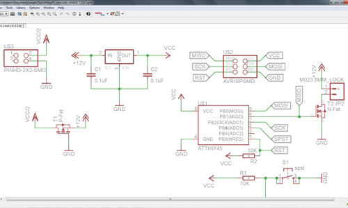
To deal with these issues the design was scaled back, dropping the SD card and opamp. As well as switching the chip back down to an attiny45. This would be sufficient to test a few additions to the circuit without trying to do everything in one giant step.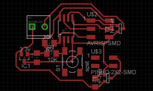
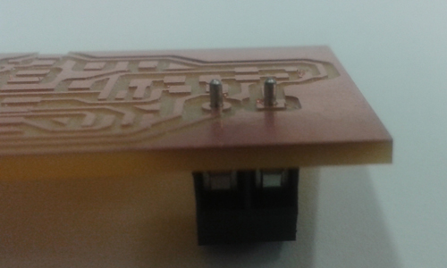
The screw terminals that we have in the inventory don’t use 2.54mm pin spacing and I was concerned that the footprint I had selected wouldn’t work. So I printed a copy of the board on paper at 1:1 scale and tested the part before milling the board. The footprint was fine but doing the test first save me from potentially having to drill out the holes later.
Eagle can output a bill of materials, making correctly selecting and placing components easy.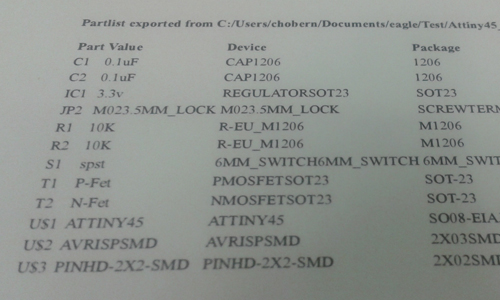
Despite having 4 legs the button is a single push single throw, rather than a single push double throw its footprint might suggest. The solid sections on the bottom of the push button indicate which way the common terminals run to help with orientation.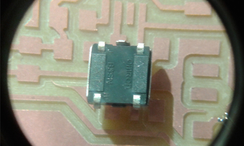
Completed board ready for testing.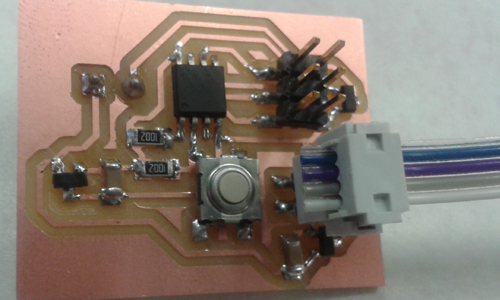
Update
In week 12 I had another crack at working with a speaker, making this circuit work in a slightly different way.
In week 14 I also used a speaker and another approach.
Tools used this week:
Hardware:
Roland MDX-20
Software:
Eagle
Tutorials links or references used
Files produced
Archived files