Input Devices
The challenge:
measure something: add a sensor to a microcontroller board that you’ve designed and read it
Plan of attack:
Use the next two weeks as a development opportunity for my final project by building the input and output projects into one board that can demonstrate some of the basic functionality im hoping to implement. For the input project im attempting to attach and capacitive touch sensor and SD card.
Touch triggered sound
The main objective of this board was to play a sound stored on the SD card when the touch sensor is triggered. To achieve this the first step was to implement the two input devices. The production workflow for this week was very similar to what I followed in weeks four and six so ill be glossing over some of the more repetitive details.
Having not successfully made a touch based project before I did a bit of reading and found a few different ways that might achieve what I was looking for, but a common theme between them was emphasising that importance of a good ground connection on the board.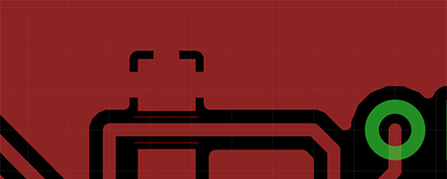
So heeding that advice I added a ground pour to the PCB. Eagle has built in support for both ground plane generation and the thermal isolation that pads attached to it require. 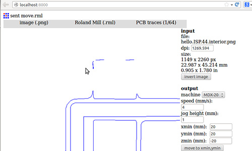
Unfortunately when this design reached fab modules for milling I discovered that the tracks were too small for the bit and were being ignored. Without them it would be very difficult to solder components to the ground plane as it would just act like a giant heat sink.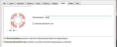
The thermal isolation settings can be found under Tools > DRC > Supply when working in board mode of Eagle 7.2.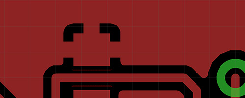
Pushing the spacing out to 20 mil was enough to provide good clearance for the 1/64” milling bit.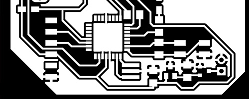
The problem of mill bit clearance was also an issue for the atmega328 chip but making the pads much smaller would of made it quite difficult to solder.
Instead I used a white mask to create a new milling path for the 0.01” milling bit that can fit between the pads.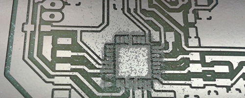
So shiny!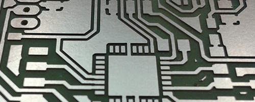
The milled out input section of the board with the touch sensor header, FTDI for serial and SD mount.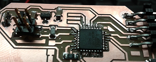
The SD mount was made by carefully modifying a 2x7 row of pin headers.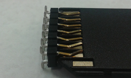
And then disaster struck, after burning the fuses the board wouldnt program. And the better part of a day was invested into trying to resolve the issue. Joints were resoldered, legs probed, fuses set and reset regulators swapped. We even broke out the scope, it showed a nice background 50Hz wave from the mains but no other activity of any kind…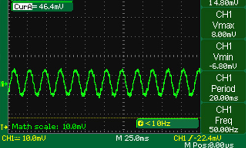
Data sheets were checked and recheck.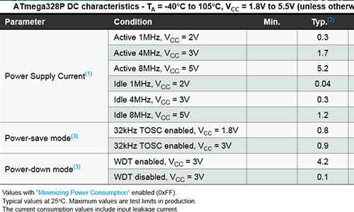
But nothing would fix the merciless “Invalid device signature = 0x000000” error.
Eventually I was able to get the chip to take code after switching out to a 5V regulator and swapping the atmega chip and changing the clock speed to 8MHz. See update below.
The next issue discovered was thankfully an easy fix. When working with serial connections the TX and RX lines should cross between devices. In other words the transmit line of one should go to the receive of the other and vice versa. In my haste to get the board ready for milling I had grabbed the wrong footprint in eagle and made a straight connection.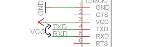
With some jumper cables in place and the board accepting code I tested out the touch pad code that had been waiting patiently all week. It worked without issue. When the pad is pressed the value drops. Yay!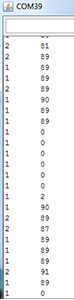
The SD card… not so much. So that trouble shooting that will have to be part of the output week.
Update
It ended up taking the class the better part of a day to resolve the underlying cause of the “Invalid device signature = 0x000000” issue two weeks later. A full write up is in week 14, but it turned out the be a dead AVRISP.
Inputs - Weekly resources
Tools used this week:
Hardware:
MDX-20
Software:
Arduino
Fab Modules
Eagle
Materials:
See eagle files for BOM.
Tutorials links or references used
Files Produced
Archived files