FabISP - Making the tool
The challenge:
Make the FabISP in-circuit programmer.
Plan of attack:
Make mill the board, populate it, test it, code it!
Approach:
Follow the workflow to produce a working ISP.
Fab ISP - When everything goes to plan
Greetings Friends,
This week we were tasked with making a FabISP. Once completed the in-system programmer will be used to write code to other attiny or atmega based circuits that we will be designing during the rest of fab academy.
To my total astonishment everything worked first time. Which is great news from a workflow perspective but also somewhat uninteresting. So this week ill break my post up a little bit differently, documenting my process but also covering some common issues that I was lucky enough not to run into and how I avoided them.
This post is kinda long, so if time is of the essence just scroll through and look at the pictures. Otherwise grab a coffee and come with me as we make a FabISP.
Board Selection
We were supplied with the board files for 5 different versions of the FabISP. The FabISP v2, FabISPkey, FabUSBPCB, hello.ISP and the hellos.ISP.res.
The first three are really awesome but require caps that aren’t part of our standard inventory. So I wasn’t able to have play around with them. However the process would of been much the same as the one followed below. That left just the two Fab.hello.ISPs the only difference between the two is that one has a 20Mhz resonator, while the other has a 20Mhz crystal with two 10pf caps to achieve the same effect. I selected the resonator version because everyone else had gone with the crystal.
File Prep
To mill a PCB we need at least three files. A trace file to define our electrical routes, a cut file to separate our board from the FR1 PCB stock and an assembly file to tell us which components to put where.
Milling the board
Fab Lab Wgtn has an Roland MDX-20 that we use to mill FR1 PCB stock. Its a great little machine but requires a little care and attention when operating. First up we attach the PCB stock to the sacrificial bed with double-sided tape. This holds the material in place while it is being milled without causing it to bow or have strange tension.
Next we’ll change the bit to suite our tool path. The Fab Lab stocks 3 different sized mill bits. a 0.01” (0.25 mm) bit for very fine traces, a 1/64” (0.4 mm) for regular traces and a 1/32” (0.79 mm) for cutting out the board and drilling any holes for vias or PHT components. Each bit should have its own tool path to avoid over use.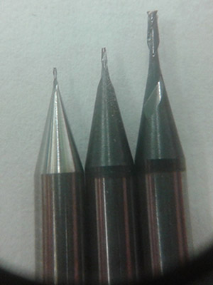
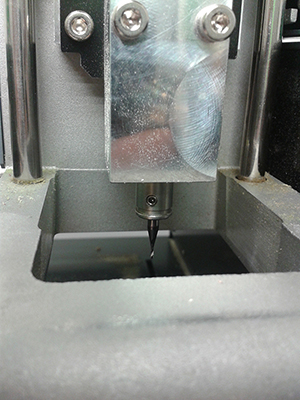
Place the MDX-20 into view mode if the light next to view is not lit, This will move the head to the back right of the bed to make it easier to change the bit. It also prevents the machine from running any commands it might be sent, like enabling the spindle.
When changing the bit its important to hold the bit with one hand while loosening the grub screw, otherwise the bit will fall out and hit the bed which could cause it to break.
Its also worth noting that the we only use one of the two available grub screws, it saves time and the second screw is unnecessary and could even be detrimental in some situations.
With the MDX-20 half prepped its time to set up our tool path using Fab modules. There are two versions of Fab modules, the older stand alone version and the new web-baised version. We are currently running the stand alone version but will shift to the web version during the course of Fab Academy. Either way the interface for both is fairly simular.
Type fab to open the Fab modules GUI and select the desired workflow. In our case Input:image(.PNG) to Output:MDX-20(.RML).
Generate the tool path by selecting the bit size you are using. Working from the smallest site to the largest. For the FabISP the 0.01” bit isn’t necessary so use the 1/64 mill trace setting to start with. Load the png containing the traces and hit make .path. Fab will think for a second then bring up a preview of the toolpath its going to cut.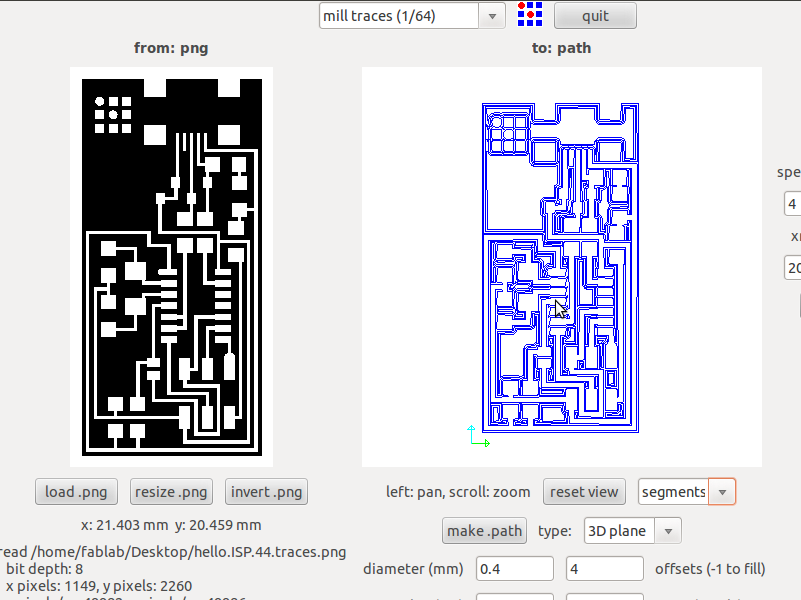
With the toolpath ready to go its time to finish setting up the MDX-20. Start by setting the X and Y axis. Exit view mode to allow the machine to receive and execute instructions from the PC. It will automatically move to the machines 0,0 point in the front left. We can then use the set xmin, ymin button in Fab modules to move the head around. Pick a location over the PCB stock that has enough room for your board. The head will drop down to its previously set Z height. If it doesn’t the tool up/down buttons on the front of the machine can be used to adjust its height. It should be set about 10mm above the lower limit to allow for travel to actually cut the board.
Hold the bit with one hand and loosen the grub screw with the other, carefully lower the bit till it contacts the material surface then re-tighten the grub screw. Its a good idea to check that there is no built up bur on the bit as this could prevent it from cutting all the way through.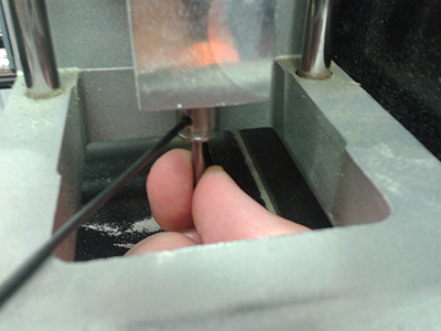
Finally its time to actually run the cut, reclick the make path and make rml buttons. Its easy to make a change and forget to re-generate the tool path then run the old version. Hit send it and wait for the board to cut.
Dont blow the dust, the copper filings will wreck havoc on any nearby electronics. Instead use a the vacuum to clean up after each path has been milled.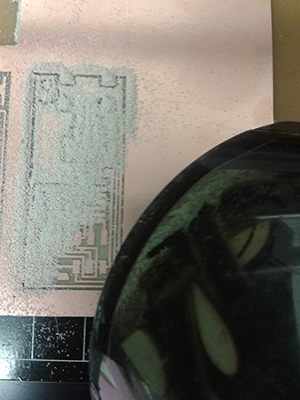
Once the traces are finished throw the machine back into view mode and change to the 1/32” bit for cutting. Load the new file, generate the tool path and reset the Z height for the new bit the same way as before. Again its important to check that the bit is resting on the surface of the material so that it cuts all the way through.
In my case it turned out that I had actually missed a critical step way back at the start. The PCB stock was already attached to the bed when I started and I didn’t check to see how securely it was attached. With the board removed I discover there was only a single strip of tape holding the board down. It could of easily twisted or lifted during cutting, snapping the bit or wrecking the board. So I was very luck.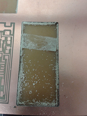
The final step in board production is a bit of clean up. Removing any filings or dust with the nylon brush. Scrape off any bur with a flat ruler then washing the board with a bit of soapy water to remove any grease from your finger prints that could mark the board.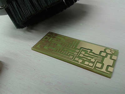
Next up we’ll solder it up, add some code and test it.
Fab ISP - Adding components
With our sweet PCB all cut its time to attach the components that will actually make it work. Fab Lab Wgtn stock the standard Fab inventory of electrical components, here they all are in nicely labeled boxes.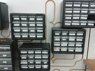
The SMD components usualy come in a tape like this: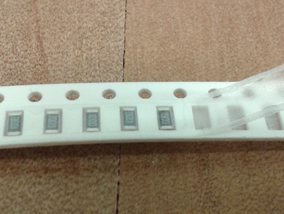
I recommend printing or writing out the BOM required for your circuit then placing each component on the page next to its name. This helps prevent confusion later on and means your much less likely to accidentally put things away in the wrong place.
One of my fellow class mates Daniel Harmsworth is building a vending machine for these SMD components that would make storing and finding components much simpler. If you do mix up your parts most of them have numbers on the top to tell you what they do.
Soldering time
Board all preped, components selected and assembly diagram at the ready its time to attach our parts. There a number of different ways attach components but good old hand soldering is by far the most common. Soldering is all about technic and practice, with a little bit of time and effort anyone can master it.
Techniceques:
Tack one side first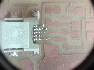
Blob it on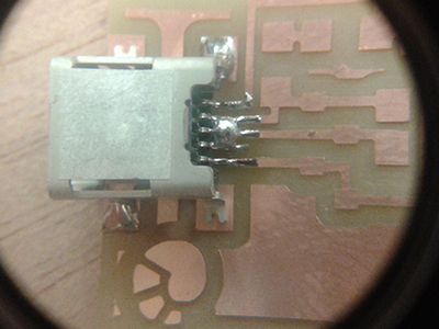
and use braid to remove excess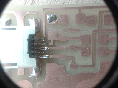
Use all of the iron
Pre tin the iron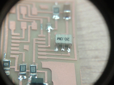
Pre-smoke tests
With the board populated its tempting just to plug it in and see if it works. But taking an extra two minutes to do a couple of test can save you having to replace dead chips further down the road. Visually inspect the board, obvious shorts, giant solder blobs or weak looking connections should be dealt with straight off the bat.
After that I check the vcc and ground rails for shorts and check all of the ISP header connections. If all of these are fine then the board should work, or at least not smoke out when its plugged in for the first time.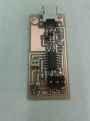
Flashing the firmware
The last step is the easiest as long as the OS is setup will all the dependencies properly.sudo apt-get install flex byacc bison gcc libusb-dev avrdude
Plug it in.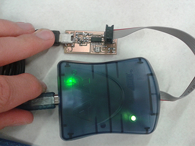
Test the power rail.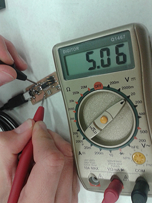
download firmware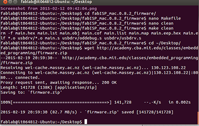
Edit make file to select which programmer you will be using.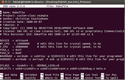
extractmake cleanmake hexmake fusemake program
Getting strange errors? Try adding add sudo the start.
lsusb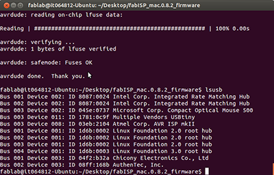
Success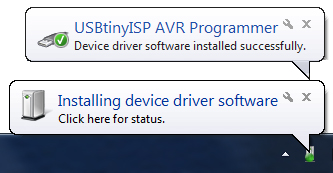
And we’re done, just in time for dinner!
Fab ISP - Note to self
Before milling
Always check the size and resolution of your cut files, they should be black and white, more than 1200 DPI and thousands of pixels wide/high. When saving out files as a PNG for Fab modules I recommend using 2000 DPI. Its a bit of an over kill but ensures that your machine is going to be operating its mechanical limits. All of the images should be the exact same size. Fab modules sets the origin to one corner of your file so if the sizes are different you’ll end up off the side of your board.
Ensure that the bed is free from debrie when attaching the stock material. The double sided tape should be applied in long even strips that are close to each other but not over-lapping. This will help prevent the board from being bowed or moving during the milling process.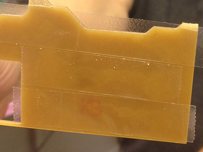
In Fab modules
Check that the milling path is going to produce the result you want. particularly if your making your own board or testing someone elses for the first time. If there are traces closer together than the diameter of the mill bit they wont be cut. You would then need to either adjust the spacing on the file, create a tool path for a smaller bit, or manually cut the trace.
Re-click all the make buttons before sending the file. Forgetting to click one will result in re-running the last path.
After Milling
Check that the board has cut through cleanly then remove it by carefully sliding a ruler underneath the board to separate it from the tape.
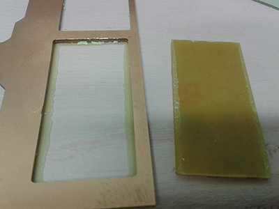
But before starting soldering there is one critical step that is often over looked. Pull up your assembly file and check every single tace and pad is correct. Missing, munted, or merged traces will be a massive pain. Its much easier to create or remove jumpers without components on your board, so throughly checking everything before starting can save a heap of time and frustration later on.
When soldering
The are a few general guides I like to try and follow when soldering a board:
Attach smaller components first, that DC power plug is just going to get in the way if its the first thing on the board.
Work from the inside out, leaving room to access the next pad will make your file easier.
Try to leave more sensitive components like ICs till later, that way you’re less likely to accidently do things like melting them.
If practical do cheap tricky parts first, things like the usb-mini plug can be easy to mess up, by getting it out of the way first you can prevent having to repeat work if the connection goes badly.
Be patient, the more practise you have the easier it gets.
We got into a bit of a discussion about whats the ‘best’ temperature to solder at. Solder melts between 180-240 degrees depending on the lead to tin ration, but melting it alone is not enough. The solder needs to freely flow between the component and its pad. My approach is to work start low and work up to higher temperatures as required. Usually around the 290 degree mark. Its also important to consider the tip size when talking about temperature, a small tip will have much less surface area with which to transfer heat than a larger one.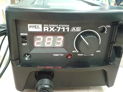
Resistors
Frist three numbers are value, the last is a 10x multiplier. R is a decimal point.
4990 = 499 omhs
1002 = 10000 ohms 10k
2001 = 2000 ohms or 2k
10R0 = 10 ohms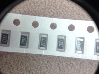
Fab ISP - Resources used
Tools used this week:
Hardware:
MDX-20
Software:
Illistrator CC
Materials:
FR1
Tutorials links or references used
Files Produced
Archived files