Beginner's Guide to Electronics Design
In which I learn not to trust Autoroute and the true meaning behind the term "ratsnesting".
I make believe.
Measure something: add a sensor to a microcontroller board that you've designed and read it.
Fab Pulse Sensor Board & Schematics(Eagle)
This week's assignment on input devices was directly related to my Final Project, which is a simple pulse sensor.
First, I decided to try making the Hello Light and Hello Reflect boards that Neil posted.


I started with Hello Light, and made a silly mistake of putting an infrared LED on it instead of the phototransistor (they look very similar).

Once I switched out the LED for the phototransistor, I was able to connect Hello Light to the Arduino IDE. I copy and pasted Neil's C code in and got some weird values. The values showing up in the Serial Monitor aren't changing whenever I pass my finger through the phototransistor on both boards.

I realized that I had completely forgotten to read Anna’s tutorial, which actually gave me detailed instructions on how to install py.serial which would allow me to read the serial data from both Hello boards.
I followed her steps for Mac. I was able to install py.serial.

And flashed the board.

But on the final step to program the board, this error occurred:
dynip-54-242:Desktop jasmincheng$ ls /dev/tty.usb*
/dev/tty.usbserial-FTG965KJ
dynip-54-242:Desktop jasmincheng$ python hello.light.45.py /dev/tty.usbserial-FTG965KJ
Traceback (most recent call last):
File "hello.light.45.py", line 62, in
File "/Library/Python/2.7/site-packages/serial/serialutil.py", line 282, in __init__
self.open()
File "/Library/Python/2.7/site-packages/serial/serialposix.py", line 289, in open
self.fd = os.open(self.portstr, os.O_RDWR|os.O_NOCTTY|os.O_NONBLOCK)
OSError: [Errno 16] Resource busy: '/dev/tty.usbserial-FTG965KJ'
I googled the error code, and it’s a very common problem for all kinds of scenarios from connecting one’s FitBIt to trying to program an Arduino. The only one solution that I could find on Stack Overflowthat made sense, was to kill processes that raises device or resource busy error, didn’t work for me. I got this following error:
dynip-54-242:~ jasmincheng$ $ fuser /dev/ttyUSB0
-bash: $: command not found
Haven't been able to find a solution for this. It would have been a good experience for me to see the Hello Light serial input data for my final project.
After some research, I found a project from Vivian Jang and Nick Lee from Cornell who designed a pulse sensor that output to an array of LED's on a t-shirt, which is very similar to how I'd imagine my final project would work. Since they provided their schematics and code, I decided to try to make their sensor. There were some new components on this board that I had never used before. One was the opamp which is used to amplify the pulse signal. The other was a potentiometer, which is is used to control the gain that is going through the opamp. With

Daniel advised me that the values for most of the components should be the same, except for the LED. I used the LED calculator from Week 6 and that datasheet for the LED Infrared Light Diode in the inventory (Part number 365-1470-1-ND-280KT) to figure out the value of the connecting resistor, which turned out to be 3.9.
There were so many components on this board, Daniel suggested that I mock it up on the breadboard, starting with the infrared LED.

Then I added the phototransistor.

Then I connected the rest of the board. It took me quite a few hours to do this. I decided to add little flags using masking tape to each component so I could easily identify them as I was stuffing the board. This ended up being very helpful since I had to re-start the board many times. It's easy to lose your train of thought while putting so many components down. Craig gave me a lot of good advice on how to use jumpers on a breadboard, and keeping groups of components together.
To test the board, Daniel suggested that I use the oscilloscope to test it. I had first used the oscilloscope in Week 6 as part of my Ultimate Troubleshooting Challenge. It's basically a multi-meter on steroids. It displays the voltage passing through the connections on your board as waves that can be magnified so that you can really understand what's happening inside the board.
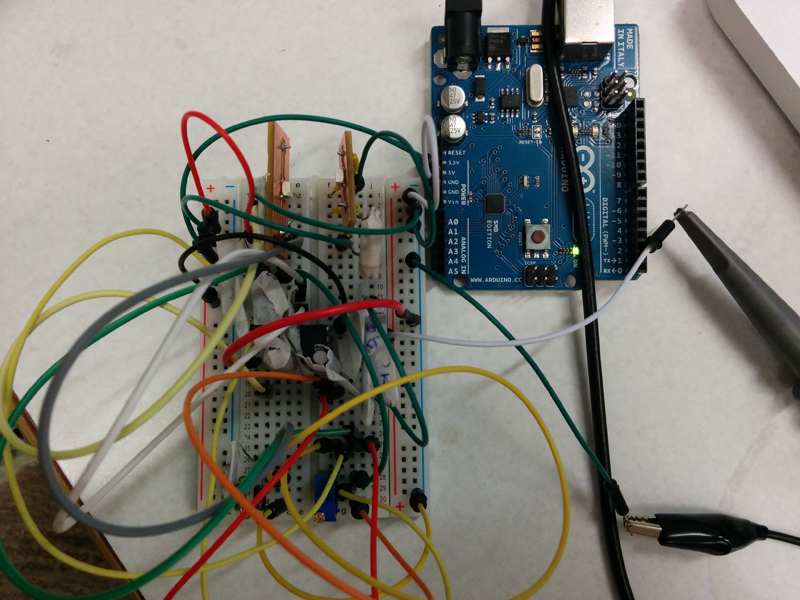

Craig showed me how to use the testing tool which has a little hook that can clip on to the little legs of your components, and a clip that needs to connect to ground. We tested out various parts of my board including the LED and the phototransistor which both showed a max voltage of 2.8V and a min voltage of -2.8V. Then we tested the 10k resistor which was connected to the potentiometer, which showed a max voltage of 3.2V and a min voltage of -3.2V. We then played with the screw in the potentiometer to see if the values would change, but they didn't. We weren't sure why this was.

But since the board appeared to be working, we decided to test it on the Arduino IDE using a sample SerialOut program. It was returning values, but when I passed my fingers in between the lED and the phototransistor, the values didn't change. I later learned that I should have put the LED and the phototransistor next to each other, not facing each other, which I will test on the final board.

I designed the board based on the original schematics provided from the Cornell project, adding a 6-pin header for power. I'll be using more through-put components than in the past, so this was an interesting soldering exercise for me.


I plugged the board into the Hello Echo board and used the oscilloscope to measure the output signal. I was quite excited to see that the signal changed whenever I put my finger over the LED and phototransistor, and asked Daniel for a second opinion. He told me that the board was producing a digital signal (square waves), rather than an analogue signal (round waves), which was what I should be seeing.
Daniel and I went on to use the oscilloscope to check VCC, LED and phototransistor. There was nothing obviously wrong on the board. When we checked the schematic, Daniel pointed out that the resistor that I’m using to power the LED was too low (3.9). I did use the LED calculator (as shown above), so I’ll need to double-check why that happened. Daniel said that I should be using a 60-70 ohm resistor.
When I went back to check the datasheet, I realized I was reading the Peak Forward Current, but I should have been using the Forward Voltage. The calculator told me that I should have at least 82 ohm resistor for the LED, which I bumped up to 100 ohm since that is what we have in stock at the Fab Lab.

To better understand what was wrong with my board, Anna offered to take a look with me. We double-checked the original schematic and the one I designed in Eagle, and discovered some really big mistakes in my connections.
The biggest mistake was realizing that the OpAmp Eagle part had flipped so legs 2 and 3 were connected wrong on my board.

I also noticed that the generic 6-pin header I was using had the opposite footprint of the AVRISP header footprint, so that was connected wrong.

So I milled a new board. It was returning a nice analogue signal, which kind of looked like a pulse, but it seemed to be picking up noise from movement of the finger, and not an actual pulse.
I was about to give up and started writing this blog post when I realized I had missed something when checking the OpAmp Eagle footprint. Not only were legs 2 and 3 flipped, but GND and VCC were flipped as well!
I tried to Macgyver the board with wires, but the problem was so deep seated, I had to mill a third board. It took me about 1 day to re-route, remill and restuff the board. I also replaced the OpAmp because I had blown it when when GND and VCC had been reversed.


I tested it on the Oscilloscope and had to scale it way down to see the differences in the signal, but I could finally see a distinguishable heartbeat. I continued to develop this pulse sensor as part of my final project, Holdable Heart.
