Making Machines Feel Things
In which I build a pulse sensor using an infrared LED and phototransistor.
I make believe.
Add an output device to a microcontroller board you've designed and program it to do something.
Servo Board (Eagle) and 1mHZ Servo Code (Arduino IDE)
For this week’s assignment, I wanted to make Neil’s servo board plus a MOSFET to provide my board with reverse polarity protection and also allow the current to go backwards and forwards. This is because I want to use a servo motor to create the feeling of a heartbeat in my final project, The Holdable Heart. I started with reading Anna’s tutorialwhich is full of great resources for a beginner electronics designer like me.
How to check Forward Current in a servo motor using a multi-meter and Arduino Uno
I chose the smallest servo motor in the fab inventory, which is the HK15178. It turns out that Hobby King is lame and doesn’t share the data sheet on the product page, so I had to test the forward current manually with a multi-meter. Craig suggested that I check the forward current of the servo motor to make sure that the pin from the micro controller I’m using (ATtiny44) has pins that can output that much current. Otherwise, I could potentially burn out the board.
To test, I used the Arduino Uno and a bread board. I then used alligator clips and jumper cables to build in the multi-meter into the circuit. This is how they’re connected.


I can see that there is quite a big range in the forward current - from 50mA - 100 mA. This means that I have to make sure that the regulator that I’m using on my board can handle 100 mA. I checked the ATtiny44 data sheet and verified that the absolute maximum rating for the the was 200 mA, which is well within the range of the servo motor I am planning to use.
Why You Don’t Need a MOSFET to run a Servo Motor
I remembered that Craig had used a FET to provide reverse polarity in Week 6, so I had to do some research around the difference between a MOSFET and a FET. To sum it up, I learned that a MOSFET is a type of FET, but not all FET’s are MOSFET’s. I also learned that MOSFET’s is more a more energy efficient way to provide reverse polarity protection than diodes.
But that raised an interesting question: if you have a MOSFET, then do you need a voltage regulator? The forumstold me that a MOSFET should act as a part of a voltage regulator. With that in mind, I decided to add the MOSFET in addition to the regulator that’s on Neil’s board.
Craig told me that Zenna had used a MOSFET on her board in Week 6, so I checked out her schematic. It showed that I needed 3 resistors:
To calculate the resistance required for the resistors, I turned to Daniel who gave us an impromptu introduction to electronics theory. It’s a good idea to read up on Ohm’s Law and Kirchoff’s Law at some point as this is the foundation of all electronics design.
To calculate the resistance I would need for the MOSFET, I had to find the Rated Gate Current for the Transistor. I found it in the MOSFET data sheet "Drain-Source Breakdown Voltage”, which tells me how much 250 uA

Using Ohm's Law, I made this calculation:
R=5V/0.00025A
R= 20,000 omhs
That is a LOT of resistance. This was when Daniel kind of turned to me and asked, “Why do you want to add a MOSFET?” And I said, “Because I want my motor to run in both directions, instead of just one direction.” So he said, “But the servo already has that built in.” So I said, “What about reverse polarity protection?” And he said, “You only need a MOSFET to run a regular DC motor. You don’t need one for servos."
So basically, I spent the whole morning trying to solve a problem that didn’t need to be solved. But such is life in Fab Academy.
The last thing I wanted to verify the 22uF capacitor that was on Neil’s board before going out to buy one (it doesn’t exist in the fab inventory). I went into the regulator data sheet (LM2940IMP-5.OCT-ND (5V) and read that the minimum capacitance is 22 uF, which can be increased without limit.

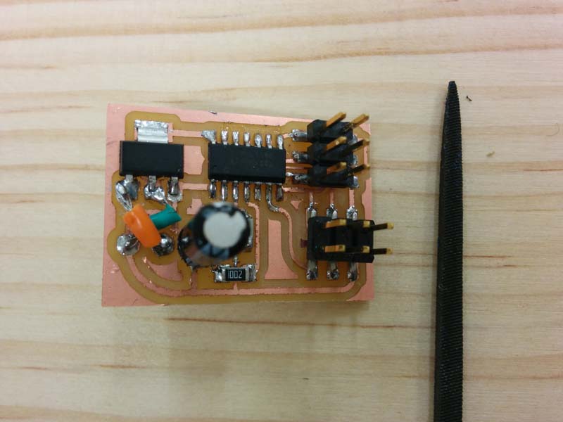
I designed the schematic based on Neil’s Servo board and I quickly put it into production.


How to get a Servo Motor to run on an ATtiny44 with Arduino IDE
When I went to program the board, I was getting error messages and the board was getting very hot.

I tested the board with a multi-meter and found nothing unusual, so I checked with Craig. He took one look at my schematic and saw that I had forgotten to include a power supply.

Rather than mill a new board, Craig suggested that I use a file and wire and fix the connections manually. This was actually a very quick and easy process, and within an hour, I had a board that was working.

But the code that I had used this morning to program the servo motor through the Arduino Uno was no longer working. We decided to pull out the oscilloscope once more to test the 6-pin header used to connect to the servo motor. We then ran a different code sample (Blink), which would give us pulse width modulation (PWM), which is easy to visualize on an oscilloscope. We modified the code to run across an array of pins (all open pins), so that we could attach the Oscilloscope on all of them to see if they were all working. We were able to see that there was current running through at a very low speed.

Craig thought that maybe the example code from Arduino only works with a 16-bit micro controller (as used in the Arduino Uno), and not with anything slower - such as the ATTiny44, which is 8-bit. I verified this in the forums.

We re-ran the code at slower processing speeds, with no avail. We also tried pasting Neil’s C Code into Arduino IDE, but this didn’t work either, and was too complex for us to figure out how to tweak. We started googling around to see if anyone had written 8-bit Arduino code for the servo, and tried a few that didn’t work. I was almost ready to pack it in and give up and Craig sent me this.
// **** ATtiny Servo Sweep Example **** //
const byte servo = 0; // Servo pin on ATtiny
int tPulse = 4000; // Total pulse length on 1 Mhz clock
int hPulse = 60; // High pulse time (60=0deg -> 280=180deg)
bool Dir = 1; // Servo direction
voidsetup() {
pinMode(servo, OUTPUT);}
voidloop() {
digitalWrite(servo, HIGH); // Set pin high to start pulse
delayMicroseconds(hPulse); // High pulse angle data
digitalWrite(servo,LOW); // Set low for the rest of pulse
delayMicroseconds(tPulse-hPulse);
if (hPulse < 280 && Dir == 1) hPulse+=10; // Rotate servo to 180 degrees
elseif (hPulse >= 280 && Dir == 1){ // Servo hit upper limit
hPulse = 280; // Keep servo angle in bounds
Dir=!Dir; // Switch direction}
if (hPulse > 60 && Dir == 0) hPulse-=10; // Rotate servo to 0 degrees
elseif (hPulse <= 60 && Dir == 0){ // Servo hit lower limit
hPulse = 60; // Keep servo angle in bounds
Dir=!Dir; // switch direction}
if (hPulse > 60 && Dir == 0) hPulse-=10; // Rotate servo to 0 degrees
elseif (hPulse <= 60 && Dir == 0){ // Servo hit lower limit
hPulse = 60; // Keep servo angle in bounds
Dir=!Dir; // switch direction}
delayMicroseconds(500); // Give servo some time to move before giving it a new position}
I ran this code in Arduino IDE and ran it on 1-bit speed. It worked. I was able to easily tweak some of the variables to change the angle of the arm and the speed. Assignment complete thanks to the wizardry of Craig Hobern!
You can download the Eagle schematic file here and the board file here.
