The Babeduino
A beautiful and user-friendly Fabduino, fully loaded for all your final project needs
Anna, Ben, Geoff, and I decided to create our own Fabduino. We call it the “Babeduino” because it’s a babe - beautiful to look at, and user friendly.
We wanted the Babeduino to be similar to the Arduino Uno with a 20mHz resonator which would allow us to use it to control servo motors. We started by studying the Fabio and the Fabkit and made a list of components that we’d like to have:
- ATMega328P
- 20 mhz resonator
- 17 In/Out's - both Analog and Digital
- Filtered and unfiltered VCC In's
- Switch allows you to flip between using a battery (filtered) and the FTDI (unfiltered) for power
- RST Button
- 4 GND's
- 4 VCC Out's
- LED for power
Version 1
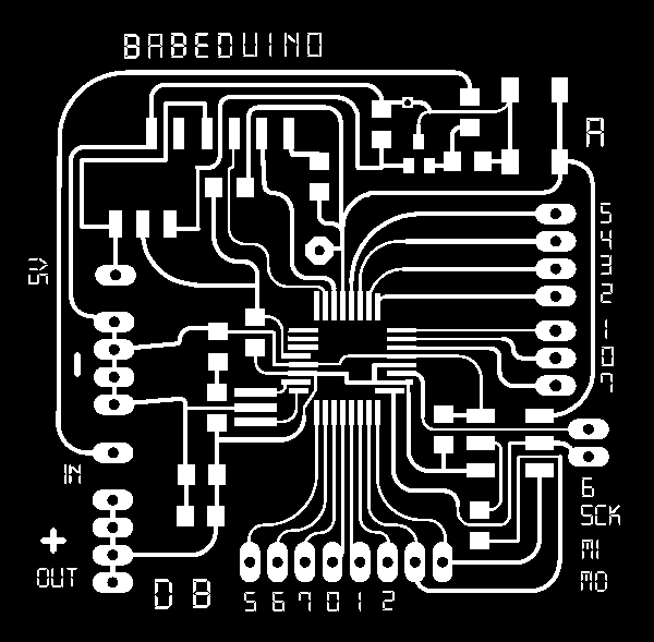
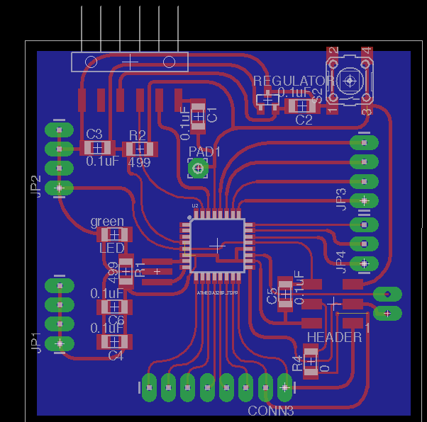
Anna designed the schematic, Ben did the ratsnesting, and I made the board pretty by making it smaller, and adding curves to the traces.
Milling & Stuffing
After we milled the first board and Anna stuffed the board, Ben noticed that the regulator was not connected to VCCIN. It turned out that Anna had connected the regulator to the FTDI VCC, and not the VCCIN.
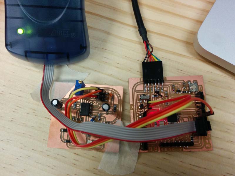
I took on the challenge of "franken-fixing" the board with some wires and it checked out on the multi-meter. Anna burned bootloader and we used a breadboard to connect the Babeduino to an LED and resistor in order to test whether or not we could program it.
When we tried to upload some LED blink example code to the Babeduino. we saw this error.
Craig pointed out that we were using the wrong boardfile, and sent us the ATMega boardfiles. We followed the readme.md instructions and re-started Arduino IDE and were able to see the ATMega in the Boards menu.
Anna connected Pin 2, but when the program did not work, we looked up the ATMega328P pinout board, it turned out that the way we routed the board, we didn't have Pin 2 connected to anything. To correct this error, we connected the LED to D5 (pin 5), and the program worked! Huzzah!
Version 2
In the second iteration, Ben realized that we couldn't have voltage input on the same pad group as voltage output because voltage input is unregulated. He recommended that we split up voltage input and output. The obvious thing to do would be to use a diode, but that means that voltage for the entire board drops, and we don't have any diodes at the lab that can handle (presumably up to) 12V.
His recommendation was to use a switch to switch between 2 different sets of pads - one unfiltered 5V pad that is also attached to the FTDI, since FTDI will always provide 5V. The other would be set of filtered pads which would go through the voltage regulator.
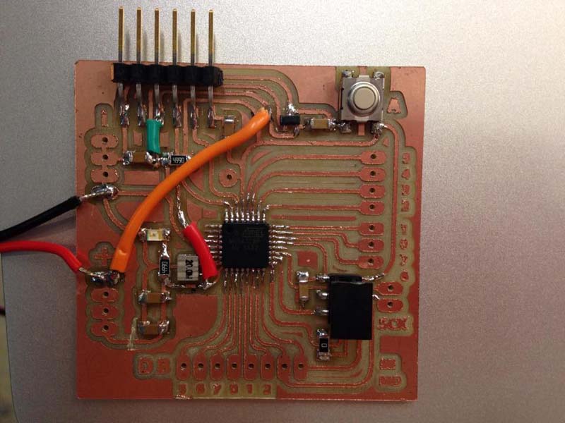
Soldering
Soldering the ATMega328P is challenging, but thanks to Ben's previous experiences, we knew that it would help to lengthen the pads on the ATMega footprint in Illustrator.
Programming
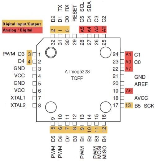
The digital pin numbers are the same on the Babeduino as the Arduino Uno, but the analog pins are numbered differently. Here is what we found:
- A0 = 14
- A1 = 15
- A2 = 16
- A3 = 17
- A4 = 18
- A5 = 19
Use this handy-dandy pinout diagram if you're not sure about anything.
The Most Common Mistake Ever
When I started programming with the Babeduino, I noticed that my pulse sensor wasn't working with it when I plugged it into pin A0. After troubleshooting, I asked Craig and he took one look at our schematic and pointed out one of the most common mistakes ever: we connected Rx to Rx and Tx to Tx. He even wrote about this in Week 11: Input Devices.
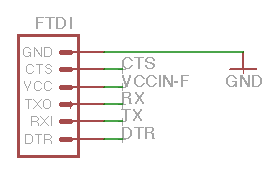
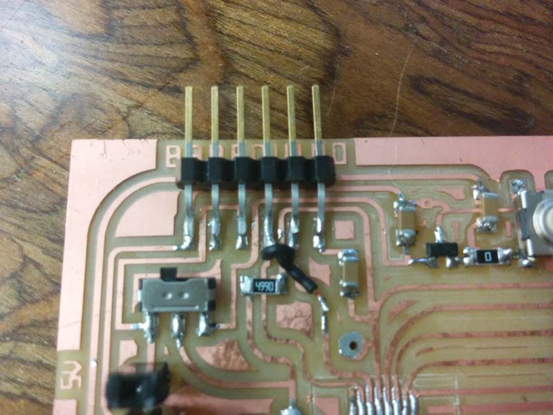
In true Fab Academy spirit, I frankenfixed this with some very elegant black single core wire. You can barely notice it!