Beginner's Guide to ISP Production
In which I learn all about troubleshooting circuit boards.
I make believe.
Redraw the echo hello-world board, add (at least) a button and LED (with current-limiting resistor), check the design rules, and make it.
Modified Hello Echo Board w/ LED and Button Board and Schematics (Eagle)
This week’s assignment was to recreate the
Before I started routing the board, Ben had some really good advice that I want to pass on here:
I also really loved his 3 principles to Ratsnesting:
First, I started by following Anna’s Tutorial
How to Create a Schematic
Schematics allow you to lay out your components and define the relationships between them. They look like hieroglyphics if you’ve never looked at one before, which was why I was glad that I didn’t have to start from scratch for this assignment.
I started off by re-creating the Hello Echo schematic and took some time to identify and understand the existing components from the existing Hello Echo schematic:
Because I was behind on my assignments due to an unexpected month back in Toronto, my fellow students at Fab Lab Wellington let me know that they advised me to also add a regulator and screw terminal.
To find all these new parts, I set-up Fab Libraries in Eagle and Craig taught me to use book-end part names with an asterix on each side (i.e. *part-name*) when searching in Eagle.
How to Calculate the Component Values
Once I had all the parts on the board, I had to add the values in for the different components. To this, I searched Octoparts by part number (I did not look up the data sheets for the screw terminal or button because they did not require values):
Within the data sheets, the kinds of values I was looking for were the following key information:
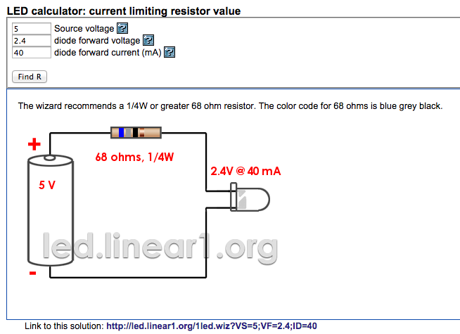
I used the LED calculator to figure out the resistor value.
My final list of parts were:
Next, I labeled the components and connected them using the “Net” function and ran the ERC test. The results alerted me to the fact that nearly none of my components were connected.
It’s difficult to explain how exactly this is supposed to work in Eagle, but one thing that helped me wrap my head around it was the realization that the labels on the components aren’t actual (or “active”) labels - as in you can’t use them. So when you think you’re connecting the LED to GND, you’re not unless you’ve actually created a label called LED and GND on top of the component using the Label function.
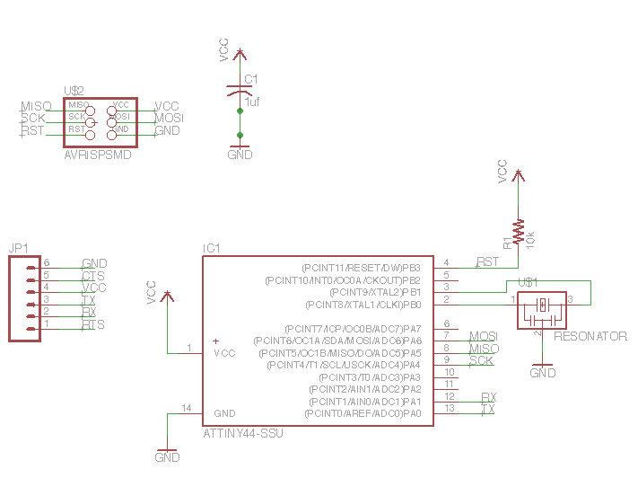
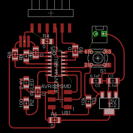
This is what the schematic of my board looked like:
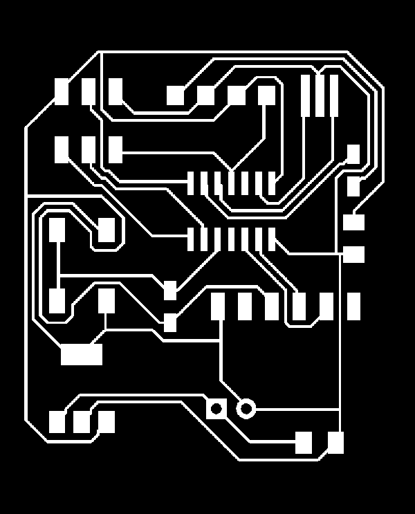
How to Create a Board
The Board takes the components of your schematics and allows you to route the circuits that run between them. You would think that the relationships and connects that you defined in the schematics should automatically create these circuits, and sometimes the software can figure it out, but most of the time, there are connections that are simply impossible to make, and the designer must add jumpers (0 value resistors) to overcome these challenges.
Despite warnings about the unreliability of the Autoroute function, I tried it and ended up having pretty good luck with it. Sure, the board did not look pretty and was quite large compared to other students’ boards, but it passed the ERC and Fab Module DRC, and since I was behind schedule, I decided to proceed with the board designed by Autoroute. This ended up being more of a curse than a benefit.
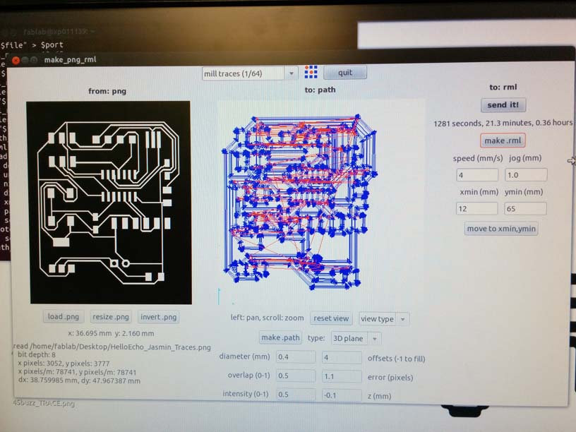
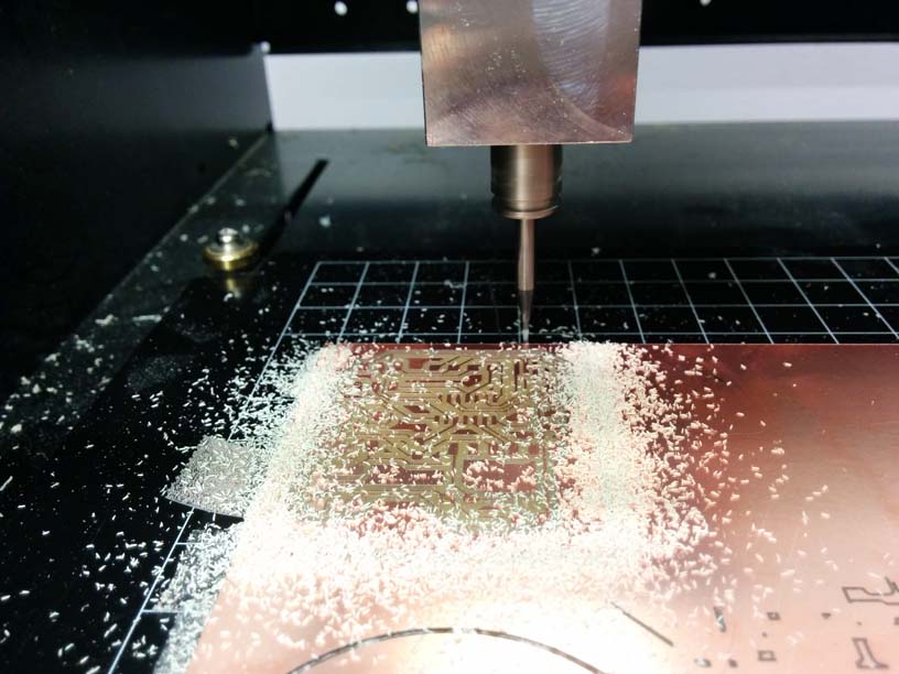
How to Your Board Design for Cutting:
Next, I followed the steps from Week 04 on how to cut the board on the Modela MDX-20.
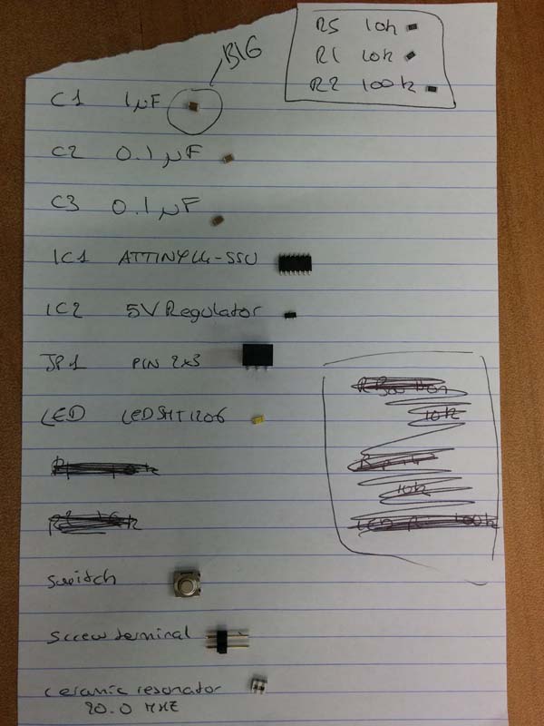
Anna, Geoff and I decided to work together to gather our components. Anna created a little chart like this to keep us organized.
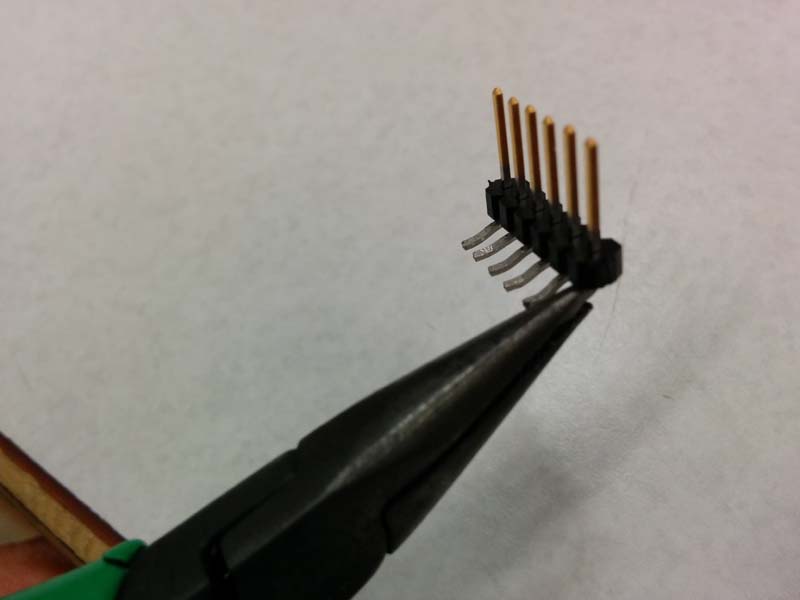
Before I went ahead and soldered the parts, I decided to double-check my schematic to make sure I truly understood where each component lie. I did this by creating a labeled diagram in Keynote, and this was when Craig alerted me to the fact that my 6-pin header was in the wrong location. The header should be at the edge of the board so that the mini USB connector could fit.

At the Regional Review, I shared my experience with Francesco and he suggested that I use pliers to bend the legs of the connector and have the USB connect vertically into the board.
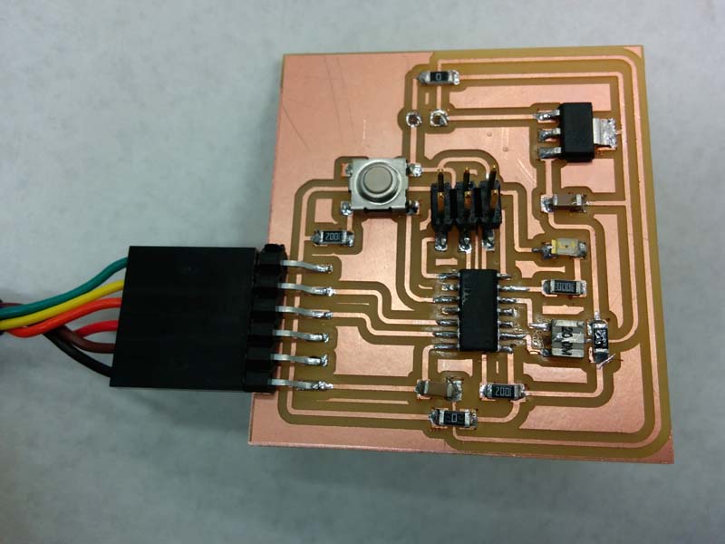
I was able to attach all components to my board with minimal problems.
And the board worked when I checked the circuit voltage.
My board appeared to be working, so I proceeded to try to program it in Week 07 only to discover that this board, was not in fact functioning. After extensive troubleshooting with both Craig and Stuart, we decided that the problem was probably the routing. I had not realized that Autoroute's default route width was much thinner than the recommended 0.016, and even though it passed both the ERC and Fab Module DRC, the routes generated by Autoroute were simply too thin and ran under components where it shouldn't have.
Don't make the same mistake I did! DO NOT USE AUTOROUTE!
Craig came to my rescue and gave me some advice on how to re-route my board:
They don't call this "rastnesting" for nothing. It's one of the most frustrating puzzles. It feels like a futile exercise, as soon as I routed a few components, I had to unroute them because it was in the way with another route. After an hour of trying to lay out the "perfect" board - a board that doesn't require any jumpers, I decided to throw caution to the wind and use as many jumpers as I could. I ended up designing a board with 6 jumpers - there were almost as many jumpers as there were components.

You can download the Eagle Board file here and the schematics file here.
