wk4 | Electronics production
Assignments :
- Make the FabISP in-circuit programmer (mill the board, stuff it, program it)
- Get the (example) board working (it's not necessary understand all of it)
Download : hello.ISP.44.cad
My notes :
24 feb 2014 | milling the board
Our tutor has set up a lunix laptop, so we could use the Modela to start milling our board.
note: the board were making is a 'programming' board.
When installed it's useful to program other (new made) boards. Aka, programmer.
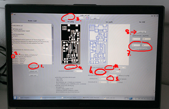
Start up the modela program by entering the right command in the terminal. (make_cad_rml)
-
About the the modela:
- the board material you want to mill needs to be held in place with a piece of double sided tape.
- change the milling head to the right thickness (the small one, 1/64)
- with changing you need to define the zero point on the z-axis for the machine.
Step 1 : load the .cad file the want to mill
Step 2 : remove the '#' symbol of the step you want to execute
(so first traces and exterior) (make sure the others in the list are turned on > with '#')
Step 3 : set the pop down menu (on top of screen to 'mill traces (tool: 1/64)'.
Step 4 : make .png
Step 5 : in the path parameters, set the error margin to 1.0
Step 6 : click the make path button to generate the toolpath. (use rest view to reset the view :)
Step 7 : set the xmin and the ymin (the starting point of the modela's milling head)
Step 8 : make .rml (then send it)
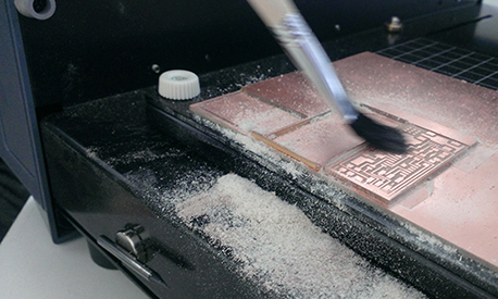
Step 9 : While the machine is running, replace the protective plastic hood.
When the machine is done, remove the hood again and use a brush to wipe away the dust.
(it's paper and copper dust, don't try to blow it away).
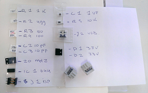
Step 10 : Next, write a list for the 'stuffing' of the board.
(add a piece of upside-down sticky tape to the 'shopping list'. This will prevent your components of getting lost or mixed up).
ok, now soldering for the first time...
Note: You need to have 2 steady hands!
So try to plan soldering in the early morning, after a good night's sleep, no coffee and with proper breakfast etc. ;)

-
About soldering :
- work from inside out, top to bottom (sometimes already placed components can be in the way, so plan ahead).
- don't try to rush it, the soldering tin needs time to melt and flow properly.
- when the soldering tin drops gets messy, stop! First remove the excess tin, before trying again.
- when the placed tin doesn't have a shiny look, you need to reheat it again (shiny is good).
- it best to have the copper squares completely covered with tin (and component).
Step 1 : place a bit of tin on one of the two copper squares.
Step 2 : place your component on top of it and pin it down with your tweezers.
Step 3 : reheat the drop of tin until the pinned component sinks in it.
Step 4 : add tin to the other side. (place a drop, keep heating it till it starts to nicely flow out).
Step 5 : add some extra tin to the first side (so both sides are nicely flowed out).
Step 6 : check if your happy, before continuing. (the more components that are already soldered,
the harder it gets to make small adjustments)
-
When done stuffing, check with the multimeter (continuity tester)
- first: press center button to get the right icon in the screen.
- second: hold the 2 (back and red) sticks together, device will beep.
- last: hold the black stick on the 'ground' (-) of your board, and the red stick on the vcc (+).

25 feb 2014 | installing the board with a windows 8 laptop
Step 1: installing winavr (this program includes 'avrdude' which we need to do the 'make' step)
Step 2: open cmd and execute 'make clean' and 'make hex'
What is 'make clean' ? It removes the old 'object and hex' files. (like throwing away a old ziped file in the bin).
What is 'make hex' ? a hex is the 'machine code' for the programmers board. (like making a new zip).
Step 3: installing Atmel studio.
We need this for the diver of the 'blue box' This 'box' is also a 'programmer'.
The new board I made is still unaware of what it is, so it needs to be installed first, hence the second programmer
(aka. blue box).
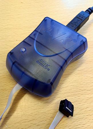
Step 4: Libusb downloaded. (this is to install the 'driver filter' for the blue box.)
To get this to work on my windows 8 laptop we need to do a 'workaround' because windows 8 doesn't allow it.
the how-to we used is from http://fabacademy.org/archives/2013/students/nielsen.michael.hviid/class04.html
- detour step 1: Move cursor to right corner of screen - select "Settings", choose "PC settings"
- detour step 2: choose "General" - Under "Advanced Startup" - choose "Restart Now"
- detour step 3: choose "Troubleshoot" - "Advanced Options" - "Windows Startup Settings" - click "Restart"
- detour step 4: choose "Disable Signature Enforcement" > now Windows starts and you can install unsigned drivers.
almost there...
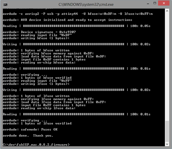
Step 5: test in cmd if avrdude work correct. (no point in trying to make the fuse,
if something unknown went wrong with all the installing steps).

Test the command line: avrdude: which programmer (-c), which port (-P) and which part to use (-p).
-
about cmd
- if you use arrow up, you get back the command line you typed before.
- typing 'xx' is useful if you don't know witch type number you exactly need to run the proper commend.
- use the 'tab key' for auto completing your text.
(it's like a sanity check, because the tab will only fill in logical options, like only files available in that specific folder.)
Getting a 'failed' response back from avrdude is only logical. No worries, this is suppose to happen.
You have know confirmed that avrdude responded to your request, but because the request is not executable.
(because the programmer board still isn't installed yet) it says failed.
Step 5: Run cmd line 'make fuse'. (a installment window should appear).
Step 6: Run cmd line 'make program'.
26 feb 2014 | de-soldering stuff and making the flat cable
Last step: de-solder SJ1 and SJ2.
Since we installed the program to the programmers board we don't need these components anymore.
The 2 components can be reused for an other board.
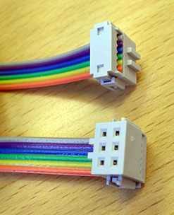
And create a flat cable with 6 wires (the colors don't matter)
Put the colored cable in the grey connector and then use the vise (the same little one used to hold the board while
soldering) to close the grey connectors.