Fab Academy 2013 · Michael Hviid Nielsen
Waag Society's Fablab in Amsterdam
· Lecture 04: Electronics Production
Lecture 04: Feb 13, 2013
Assignments: make the FabISP in circuit programmer - the
goal being to make it. Not, necessarily understand it.
Lecture Notes:
What I did:

(What I did? I made the FabISP in cirquit programmer and I din't necessarily understand what it does ;-)
Jokes aside, I guess it uses crystals (or rather just one at 20MHz) to lure the computers USB connection into talking I2C with the FabISP. I'm just guessing here....
I milled the FR1 paperbased circuit-board using Fabmodules
and a 1/64" square end mill-bit for the traces and a 1/32"
square end mill-bit for the cutout.
Important things to notice is if the correct bits are chosen
in Fabmodules and that the machine when the z-height has been
set, has enough space to move the distance put in "Bottom
height" (which is -1.7 mm for the 1.6 mm thick when cutting
the FR1 board).
The board has two jumpers which are needed to be set
(jumpered) when programming it. In one case this is done with
a blob of solder connecting two pads. The other place there is
a trace inbetween so instead a zero Ohm resistor is used as a
bridge over the other trace.
For the traces we used 4 layers and an overlap of 0.5 (which
is 50%, i.e. the first cut is the width of the mill (o.4 mm),
the next traces another 0.2 mm each go). This still leaves som
small islands on the board but it saves a lot of time not
having to remove that.
When done, the board was stuffed with components. Soldering one "leg" (I have no idea what you call the non-existant leg of a surface mount component without insulting it. Note to self: remember to ask Bas) first with a bit of solder already on the pad. This then holds the component while soldering the rest of the "legs"
With the board all done it was time to test it. I installed
WinAVR, connected the FabISP with a USB to mini-USB cable -
this was the smoketest. If there had been a short, the
computer would have turned the port off for drawing too much
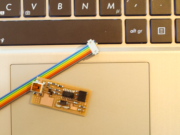
power. As this was not the case, I connected Bas' programmer
with a ribboncable and from where the firmware was downloaded
I did:
"Make fuse", then "Make program". Which succeeded, therefore I
went on to remove the two jumpers. then I connected my brand
sparking new FabISP to the computer and dida : "Make fuse"
(which failed with "initialization failed rc=-1" which
according to Bas is how it should be). Success in the black!!
What I learned:
I learned that eventhough a machine look a bit toy-like (the Roland MDX-20) there is a reason for it to be in the Fab Lab inventory. It is actually pretty precise when milling circuit boards. In fact the quality of the milled board is tough to trumph with my own "skills" when soldering surface mount components. The stuff Neil Gershenfeld said at the lecture about too much coffee is no joke at all. So Green Tea in the morning for me from now on when the afternoon is about soldering..
I didn't really have any problems and the board worked
without any debugging was needed. One thing though: I am on
Windows 8 and this gave me some trouble because the admin in
Win 8 doesn't actually have admin rights when it comes to
installing unsigned drivers (as for the USBTiny acting as
programmer). This led to the following detour:
· Move cursor to right corner of screen - select
"Settings", choose "PC settings", choose "General" - Under
"Advanced Startup" - choose "Restart Now" (the computer now
takes a little longer to boot)
· In the Boot Menu choose "Troubleshoot" - "Advanced
Options" - "Windows Startup Settings" - click "Restart" (now
the computer restarts)
· Choose "Disable Signature Enforcement" - now Windows
starts and you can install unsigned drivers (until you reboot
I guess)
· I had downloaded the driver from Lady Ada (who also
has this description but for win 7/64bit: http://www.ladyada.net/make/usbtinyisp/download.html)
and this worked fine