

week 4.
This week the assignement was 'electronics production: the FabISP in-circuit programmer'. In order to achive it, we had 3 different tasks to be acomplished:
1. Milling the board
2. Stuffing the board
3. Programming the board
1. Milling the board....
- - - - - - -
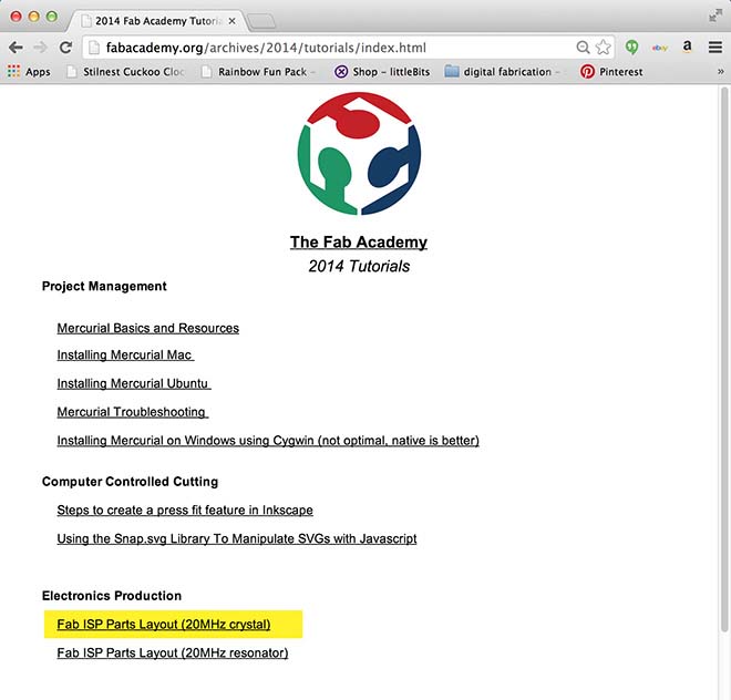
fabacademy.org/archives/2014/tutorials/index.html
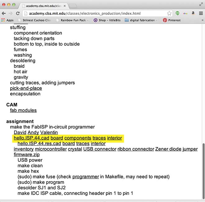
The first task was to download the the drawings of the circuit to be printed:
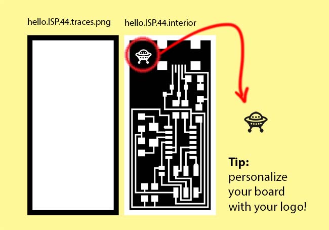
- TRACES
- INTERIOR
- - - - - - -
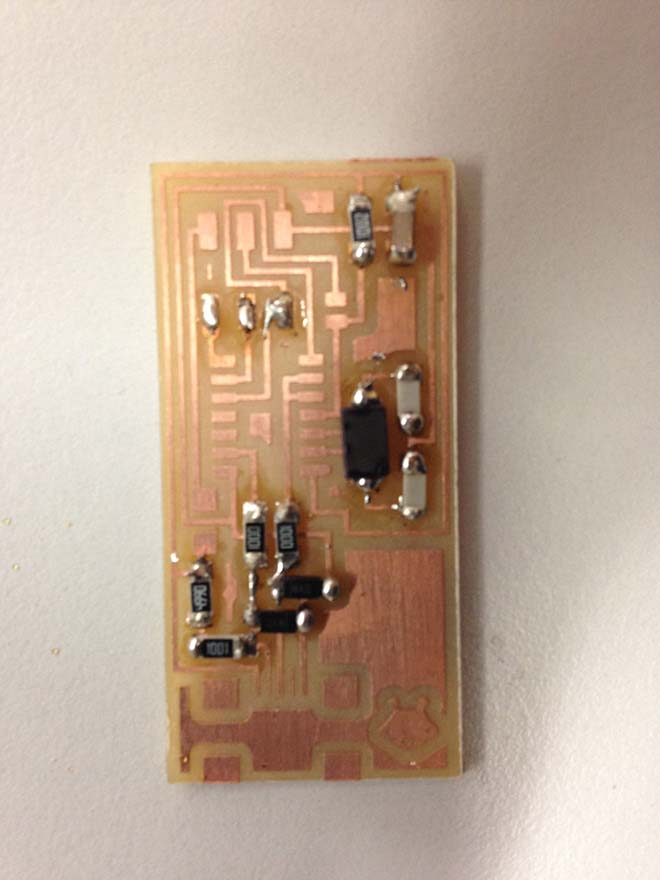
I personalized my board with a little UFO icon, to add fun to it.
- - - - - - -
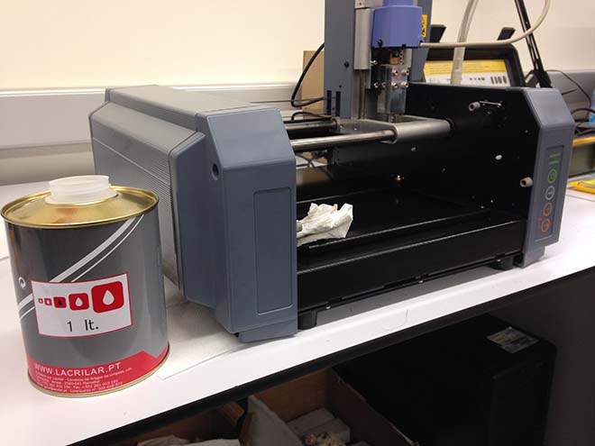
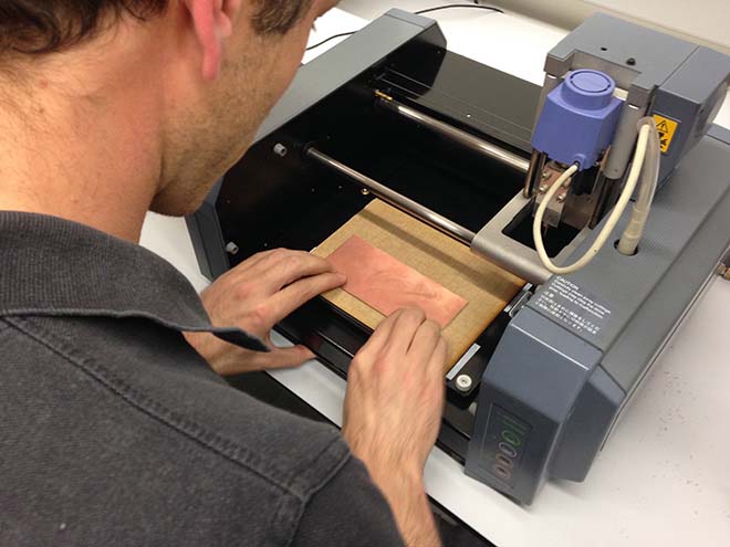
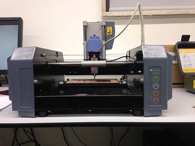
We started by cleaning our Modela with acetone and paper tissue. It's very important to keep things tidy and clean around the lab, but most important it avoids dirt to deposit around the milling area of the machine, wich can lead to misalignements in the z axis and ultimately it can destroy your PCB.
- - - - - - -
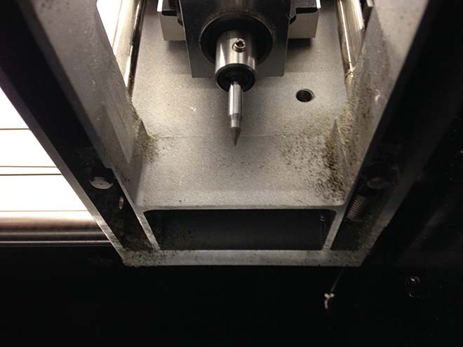
Then we installed the mill. We didn't receive the bits in time, so our instructor Ferdinand meyer made our own! We didn't really know if this hack was going to run smoothly, but it did, and at first run! Congratulations Ferdie!
- - - - - - -
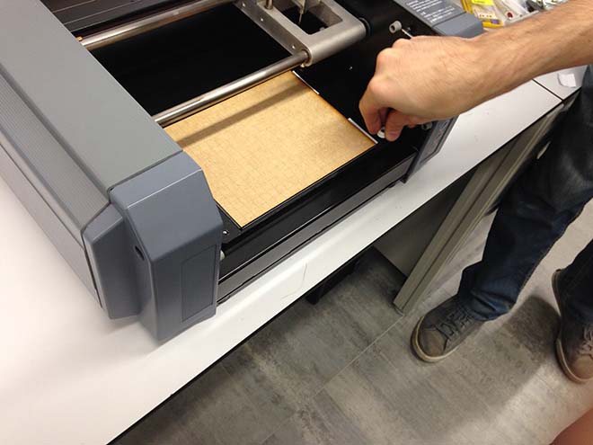
It was now time to install the sacrifice board. it's a piece of wood, cut in the laser cutter that is glued to the Modela working area, and it works as a protection for the machine, in case the mill starts to go lower on the z axis than it should. Like all things in precision milling, it needs to be completely flat. A difference in micrometers can ruin your board.
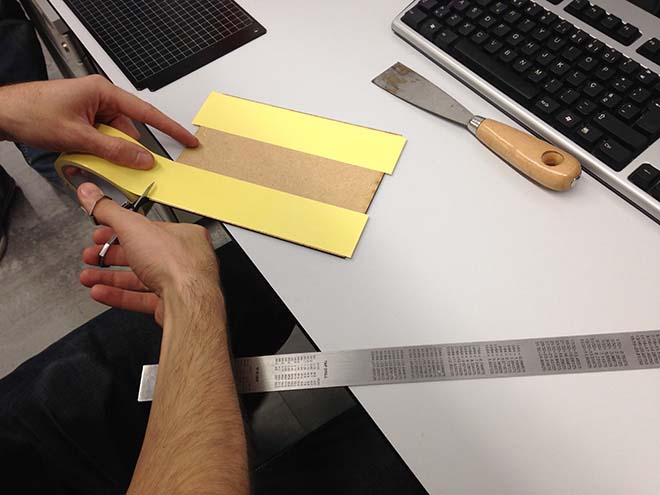
For it do adhere to the working board of the modela you have to use doublesided tape.
TIP: when cutting the doublesided tape, cutt it 1mm wider, in each side, to the sacrificail board. It will help you detaching the plastic layer of the tape, by folding it in the direction of the board the difference in flexibility of the tape it self and the protection layer will make it sepprate and it will be asy to remove the protection layer.
- - - - - - -
Apllying it in the modela working area, beeing carefull with maantaining it aligned with the white grid on it..

- - - - - - -
lock the plate to the machine using the machine screws..
- - - - - - -
Put some double-sided tape in the PF4 board.
- - - - - - -
use your fingers to press the PCB board agaisnt the sacrifice board , for it to be strongly attached to the board and tays exactly flat.
- - - - - - -
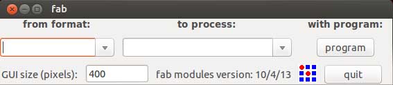
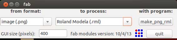
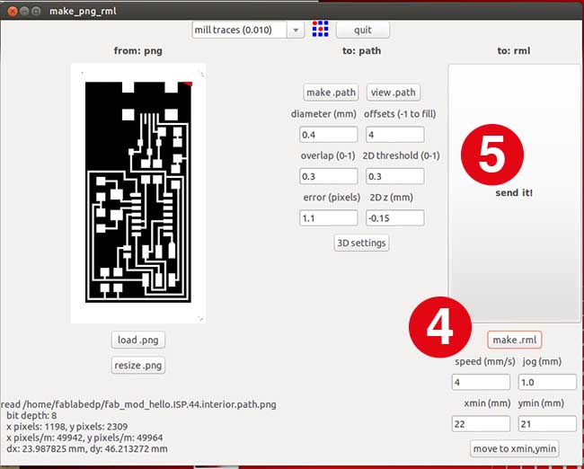
We used FabModules to PRINT and CUT the boards.
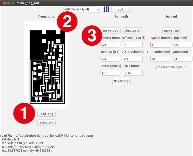
PRINTING with FABMODULES
1 - load png
2 - preset - mill traces
3 - make path
4 - make .rml
5 - send it
- - - - - - -
We had to assign a X and Y point through menu (move to xmin,ymin), and then set a Z point by pushing the VIEW button and then using UP and DOWN buttons in the Modela
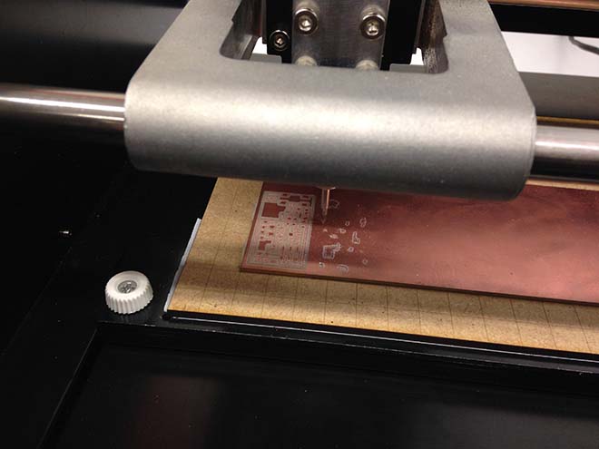
We were now ready to start printing.
- - - - - - -
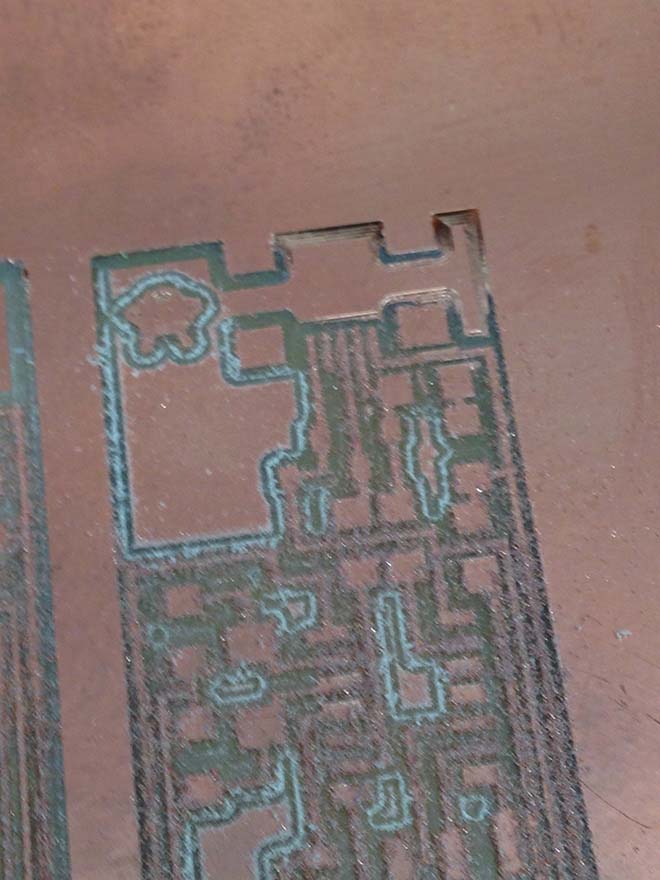
These settings needed some tunning, since at the top of the board it didn't milled deep enough. This happened not because of lack of precision of the Modela, but because the board wasn´t completely flat (and every micrometer counts)
- - - - - - -
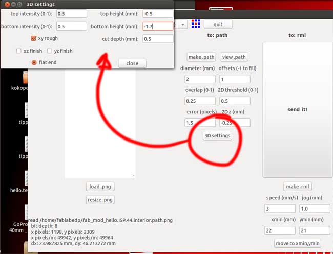
We corrected the setting in 3D SETTINGS
- - - - - - -
After correcting the settings, we were off to print the boards with all sets properly tunned.
WHEN YOU NEED TO INTERRUPT AND DISCARD A JOB:
1 - print VIEW in the MODELA
2 - open TERMINAL
3 - insert ps -e | grep cat

4 - you'll get a list of processes and you have to identify wich one relates to the job you want to discard (in this example, it was 1877)
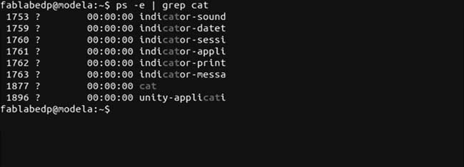
5 - insert kill 1877

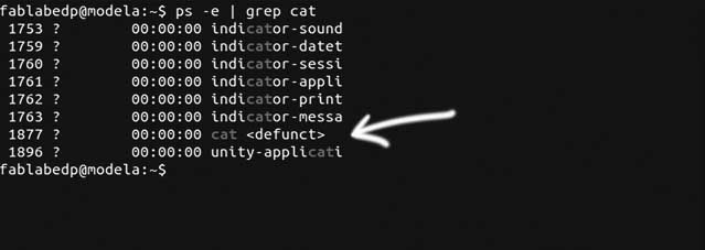
6 - once again insert ps -e | grep cat
7 - confirm that the killed process shows up as 'defunct'
8 - In the Modela, press UP and DOWN simultaneouslyb> to delete the process from the machine ( the previous commands in Terminal were to delete it from the computer)
CUTTING THE BOARDS
Using the 3d settings to make the mill to go deeper in the z axis, we cut the boards out.
- - - - - - -
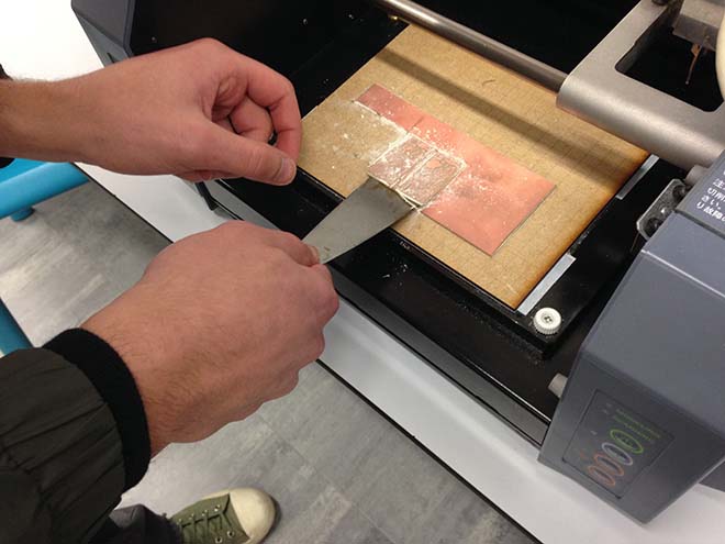
With the help of a spatula, we carefully removed the boards. They looked a little rough, so the next step was to remove all the excess material.
- - - - - - -
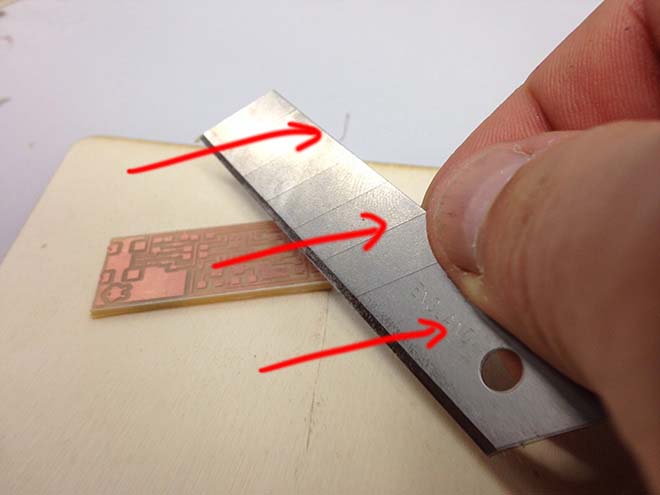
Using a x-act blade (a big one) rotated in a small angle with the board, and some steady and firm movements, we gently slid the blade in the shown direction to scratch off the dirt.
- - - - - - -
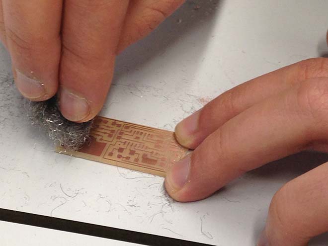
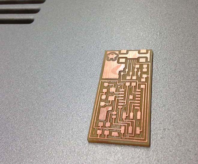
The finishing was made with steel wool, gently scrubbed ina tip to tip movement, twice to each side, to polish the copper.
- - - - - - -
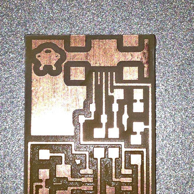
Beautiful PCB, innit? :)
Stuffing the board....
- - - - - - -
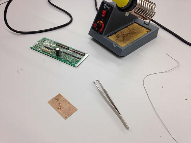
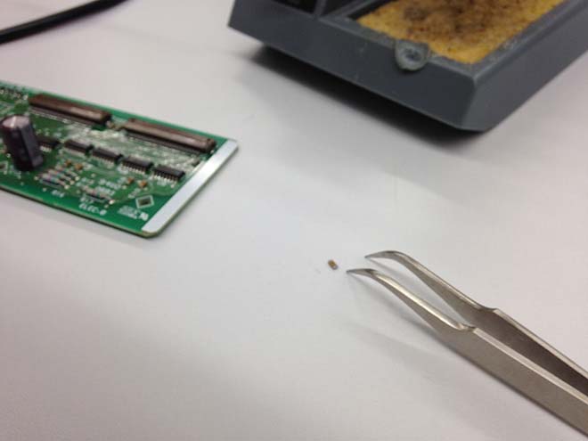
Now it was time to stuff the board with the components. But because i don't have experience with soldering and didn´t wanna risk ruining my PCB at first attempt, i started by trainning with a old pcb we hab in the lab....
- - - - - - -
... and getting used to the tinny dimensions of the components (and there are much tinnier ones, can you believe?
- - - - - - -
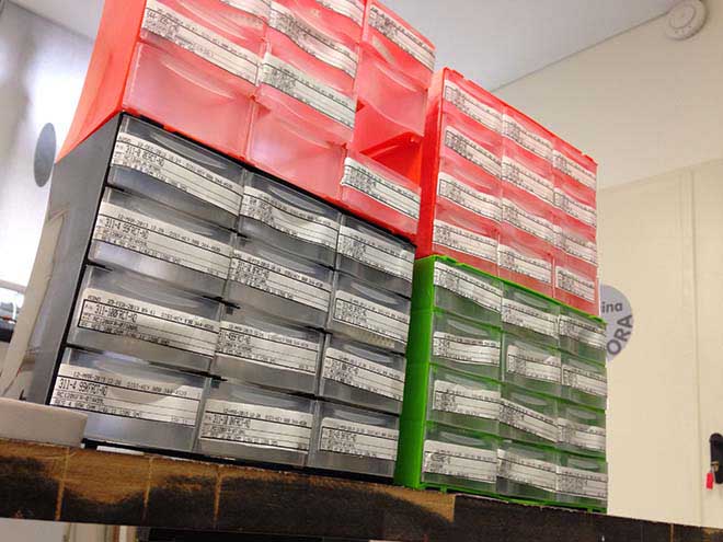
here at the lab we bought some storage/sorting boxes for the components, in order to make things tidier and avoid switching components. It was now time to collect the componentes necessary for staffing the board.
- - - - - - -
I washed the PCB with tap water and handsoap to remove all dirt and grease (otherwise i would have problems with the solder not sticking properly).
- - - - - - -
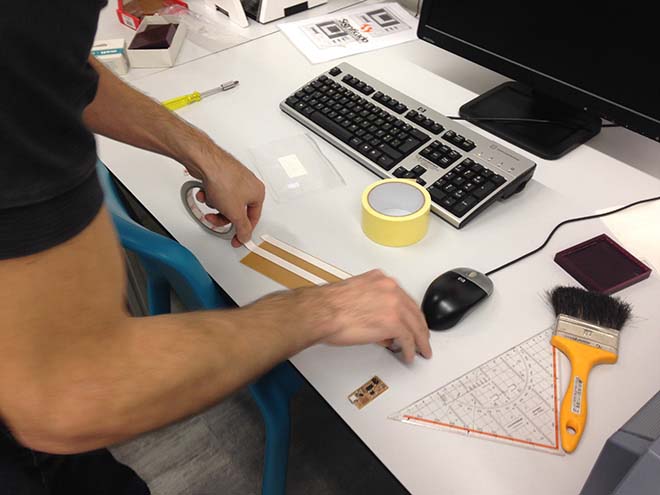
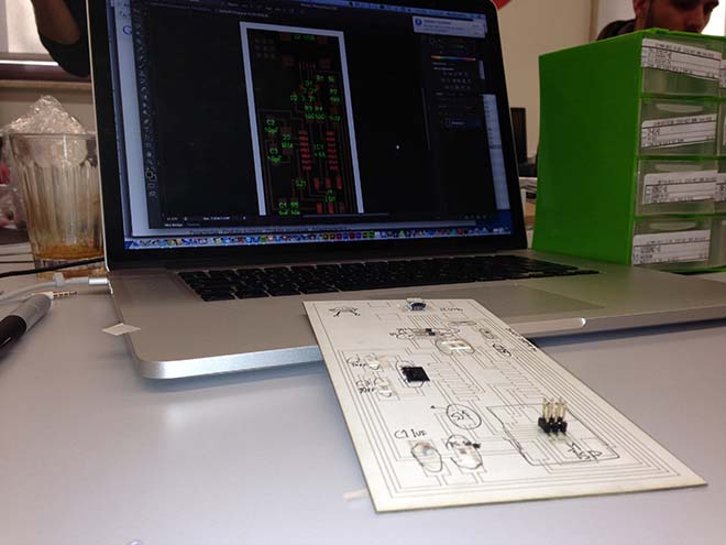
We picked the components from the storage unit using a laser-printed card with a scaled circuit and attached them ther with double-sided adhesive .
- - - - - - -
i started soldering the components using the rule FROM THE INSIDE OUT and FROM LOWER TO TALLER
- - - - - - -
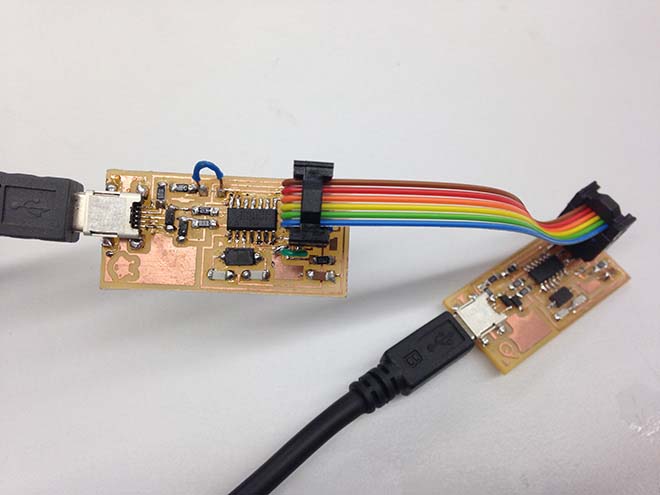
It wasn't easy to solder such tiny components, the biggest difficulty was to solder the mini-usb, it was really nervewrecking! but in the end, and after assembling a flatband cable from scratch using a video tutorial (https://www.youtube.com/watch?v=p1yZKT3Yock), the result was beautiful!!
Programming the board....
- - - - - - -
After a lot of attempts on understanding how to programm the board, and wich steps to take, i ended up chosing this one:
http://academy.cba.mit.edu/content/tutorials/akf/programming_FabISP.html
It was the best in describing how to do it in a Mac.
In resume, the procedure on a Mac is:
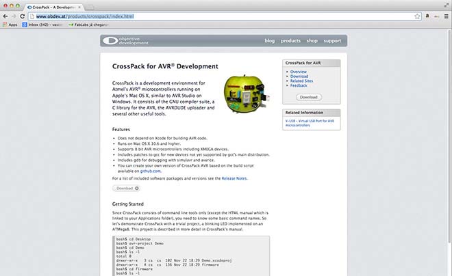
- download and install CROSSPACK AVR
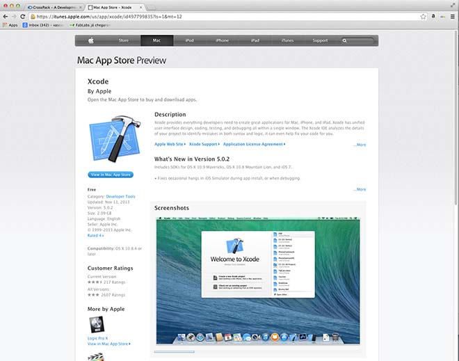
- download and install XCode (to get "MAKE")
- download and install the firmware for the microcontroller (you can download it here FabISP Firmware for MacOS 10.8.2
- - - - - - -
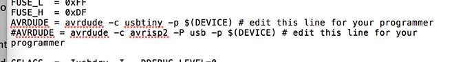
EDIT THE MAKEFILE
In the firmware folder, search for the file makefile.
For the AtTiny micro-processor:
Open it in a texteditor and uncomment (erase the '#') in the line that says:
#AVRDUDE = avrdude -c usbtiny -p $(DEVICE) # edit this line for your programmer
and put a # in the beginning of the line that says:
AVRDUDE = avrdude -c avrisp2 -P usb -p $(DEVICE) # edit this line for your programmer
Save the changes.
The result should be:
To compile the firmware, type:
make clean
Then type:
make hex
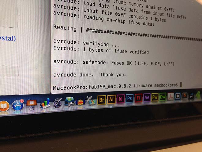
To set the fuses so your board will use the external clock (crystal), type:
make fuse
Next you want to program the board to be an ISP.
Then type:
make program
- - - - - - -
NOTE:
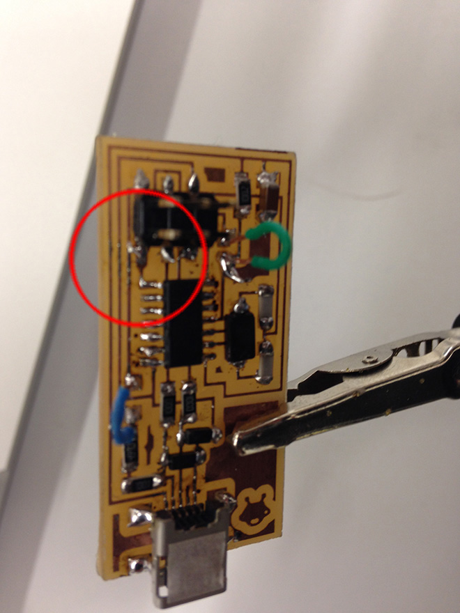
I got a error 'check for your connections' and discovered there was a bit of solder connecting 2 tracks in the PCB. After correcting the situation i got on with the programming.
- - - - - - -
But it finally was working properly!!
- - - - - - -
READY TO RUUUUUMMMMBBBLLLLLEEEEE!!!
You can download the design files here