.INPUT DEVICES.
This week was all about that

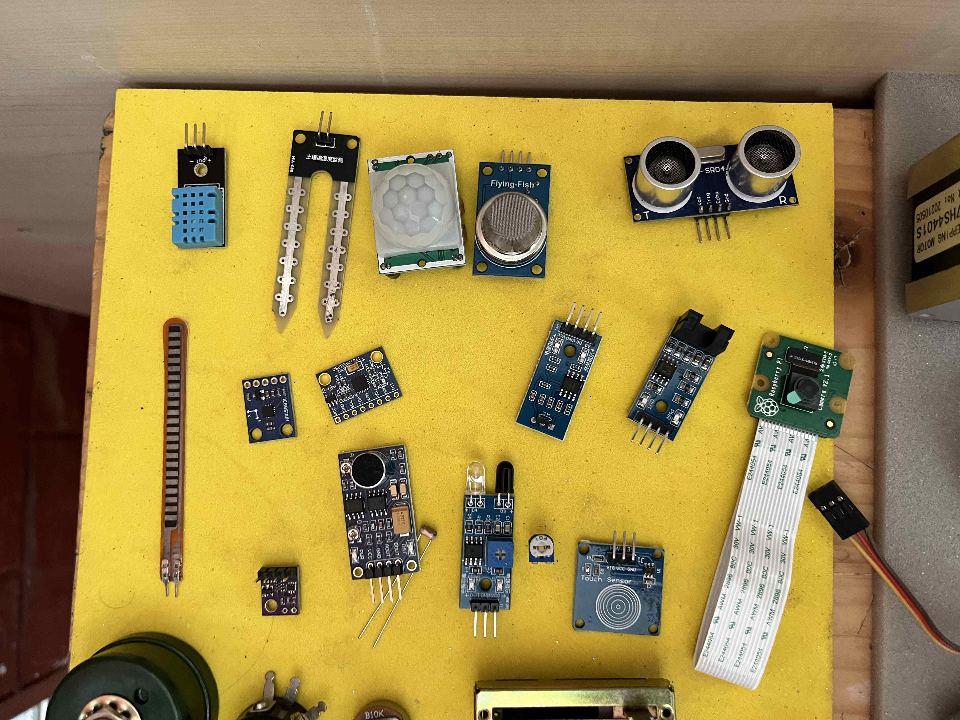
Testing out sensors
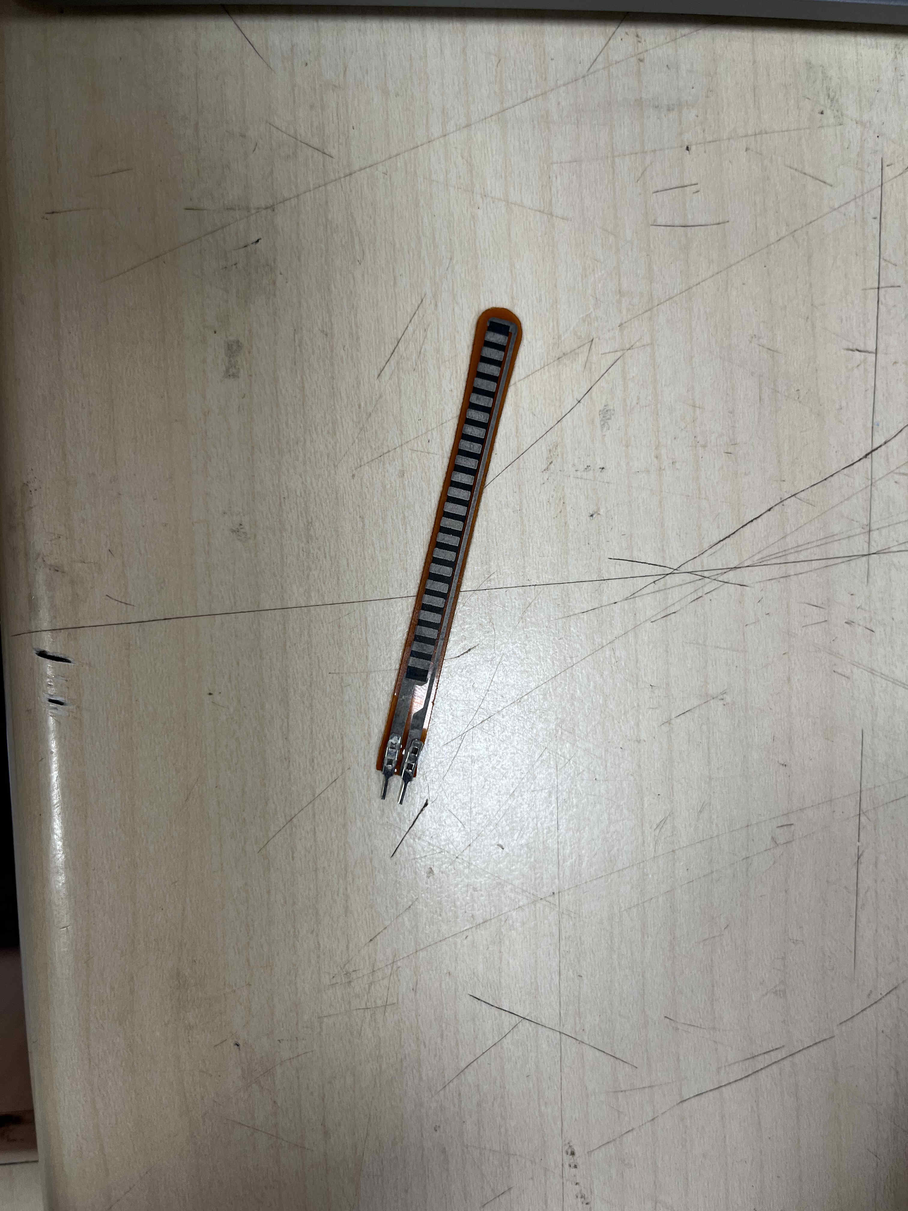
Flex Sensor
A flex sensor is a component that changes its resistance when bent. It is commonly used in wearable tech, gloves, and motion detection systems.
How It Works
Inside the flex sensor, there is a conductive material. When the sensor is straight, the resistance is low. When you bend it, the conductive particles move apart, increasing the resistance.
👉 Less bending = Less resistance
Usage with Arduino
The flex sensor is usually connected in a voltage divider circuit. The Arduino reads the voltage change using an analog pin and converts it into values that represent how much the sensor is bent.
Applications
- Gesture control gloves
- Robotics
- Medical devices
- Gaming controllers
GPIO Pins
GPIO stands for General Purpose Input/Output. These are programmable pins on microcontrollers like Arduino and Raspberry Pi that allow you to interact with electronic components.
How It Works
Each GPIO pin can be set as either an input or an output.
- Input: Reads signals (e.g., button press, sensor data)
- Output: Sends signals (e.g., turn on LED, control motor)
👉 OUTPUT = Sending signals
Digital vs Analog
GPIO pins can work in different ways:
- Digital: Only HIGH (1) or LOW (0)
- Analog (on some pins): Reads a range of values (e.g., 0–1023)
Usage Example
For example, you can connect a button to a GPIO pin as input and an LED to another pin as output. When the button is pressed, the microcontroller reads the input and turns on the LED.
Applications
- Controlling LEDs and motors
- Reading sensors
- Home automation
- DIY electronics projects
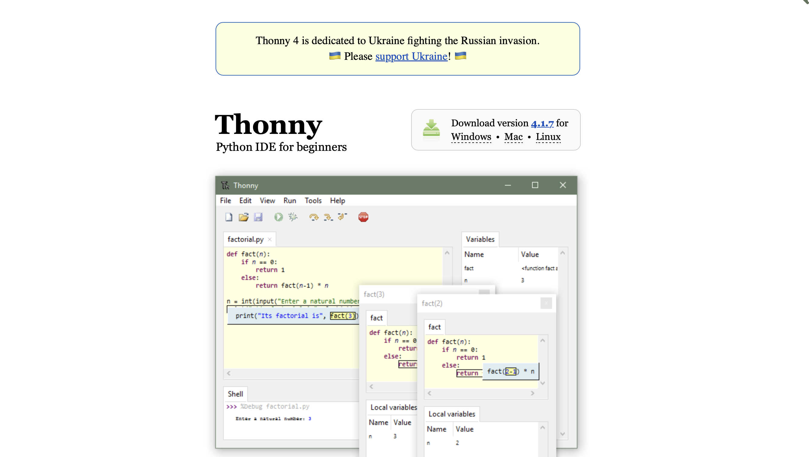
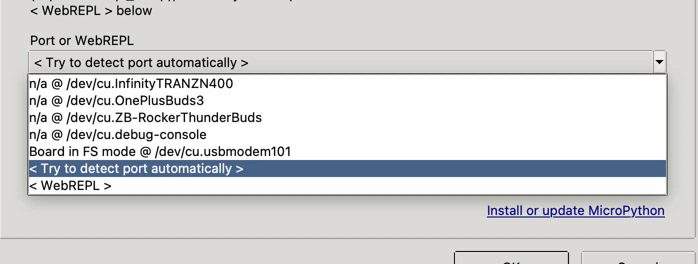
For a new challange I tried micropython this time
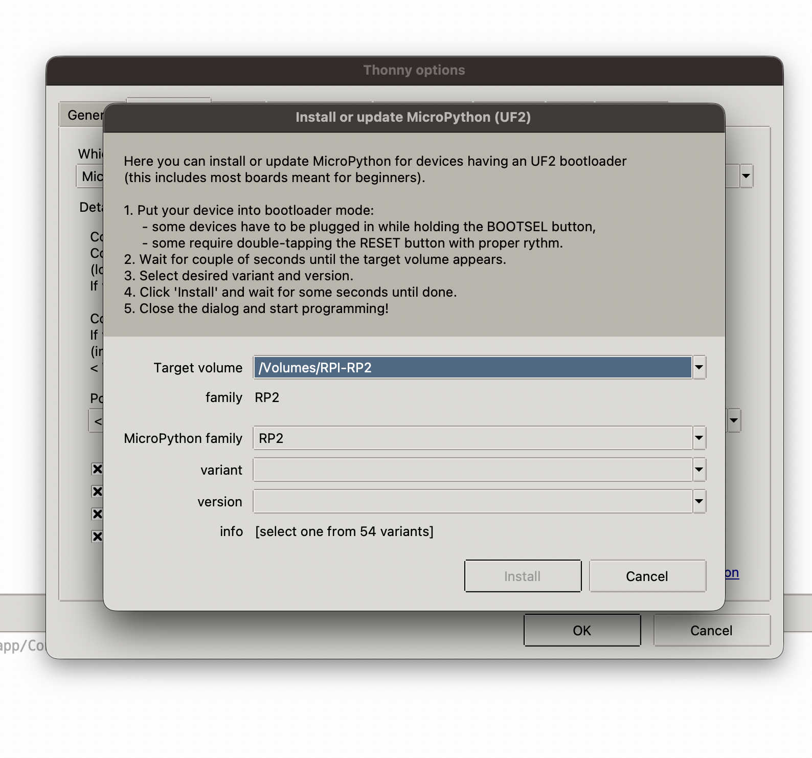
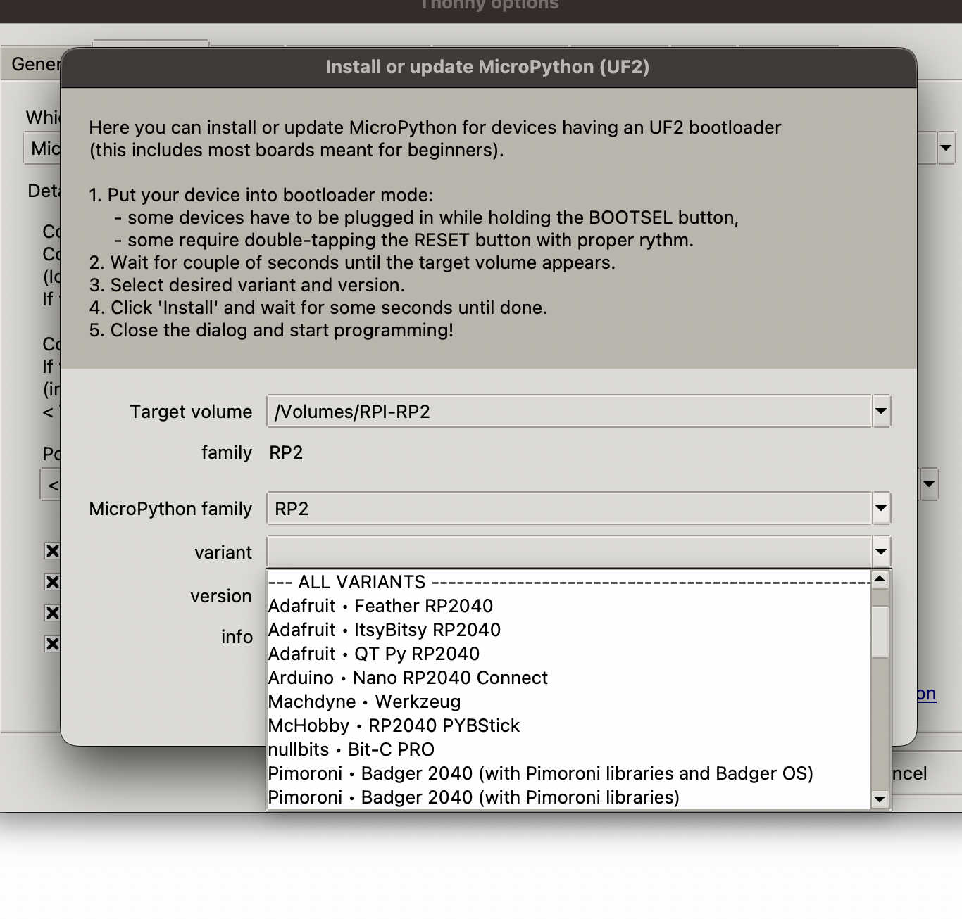
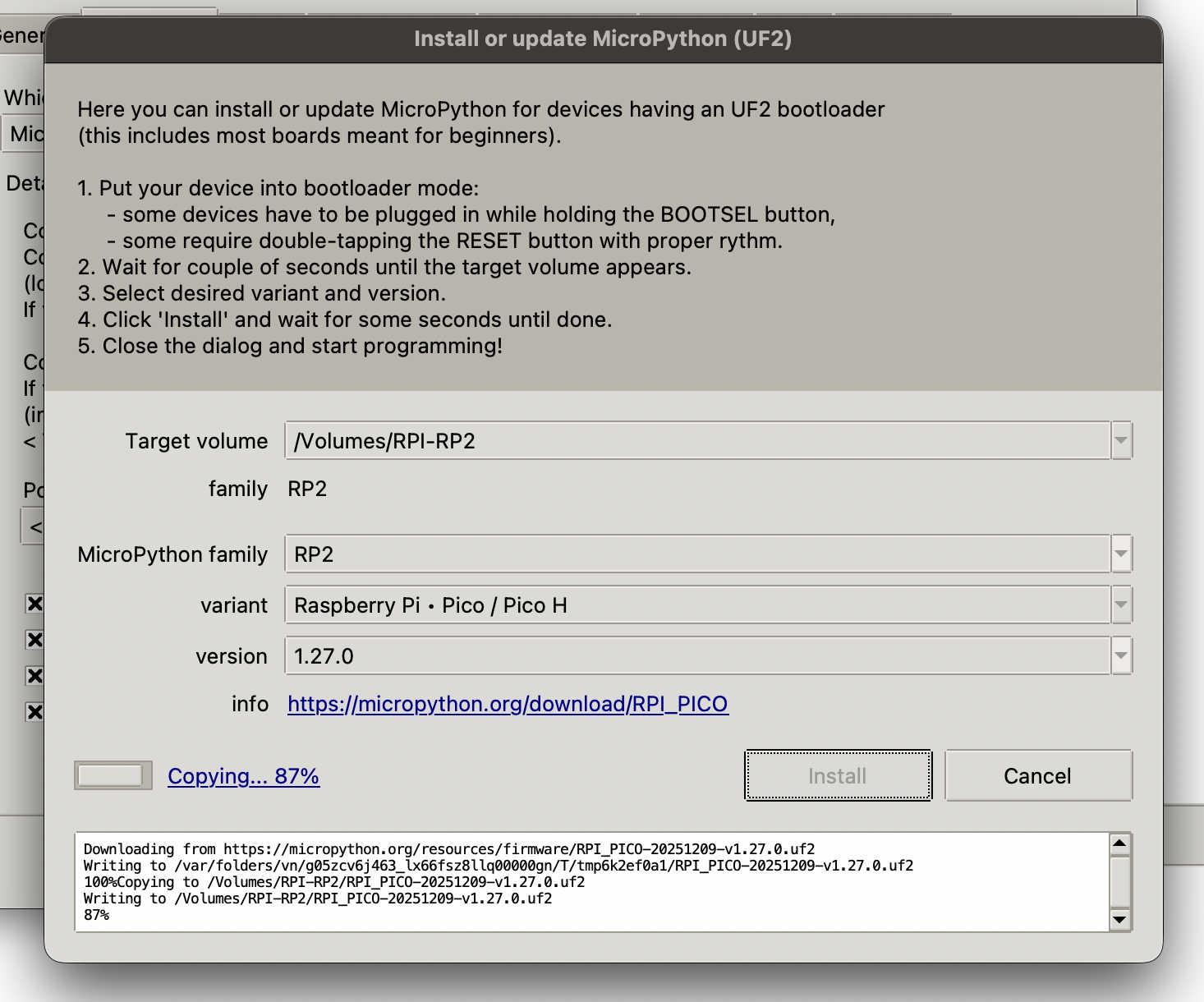
Installing Editor for micropyhton
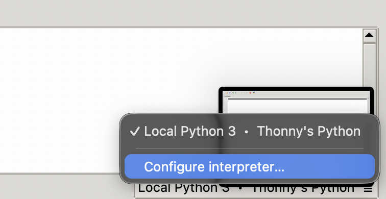
On the bottom right click the loacl pyhton3, then click configure interpreter
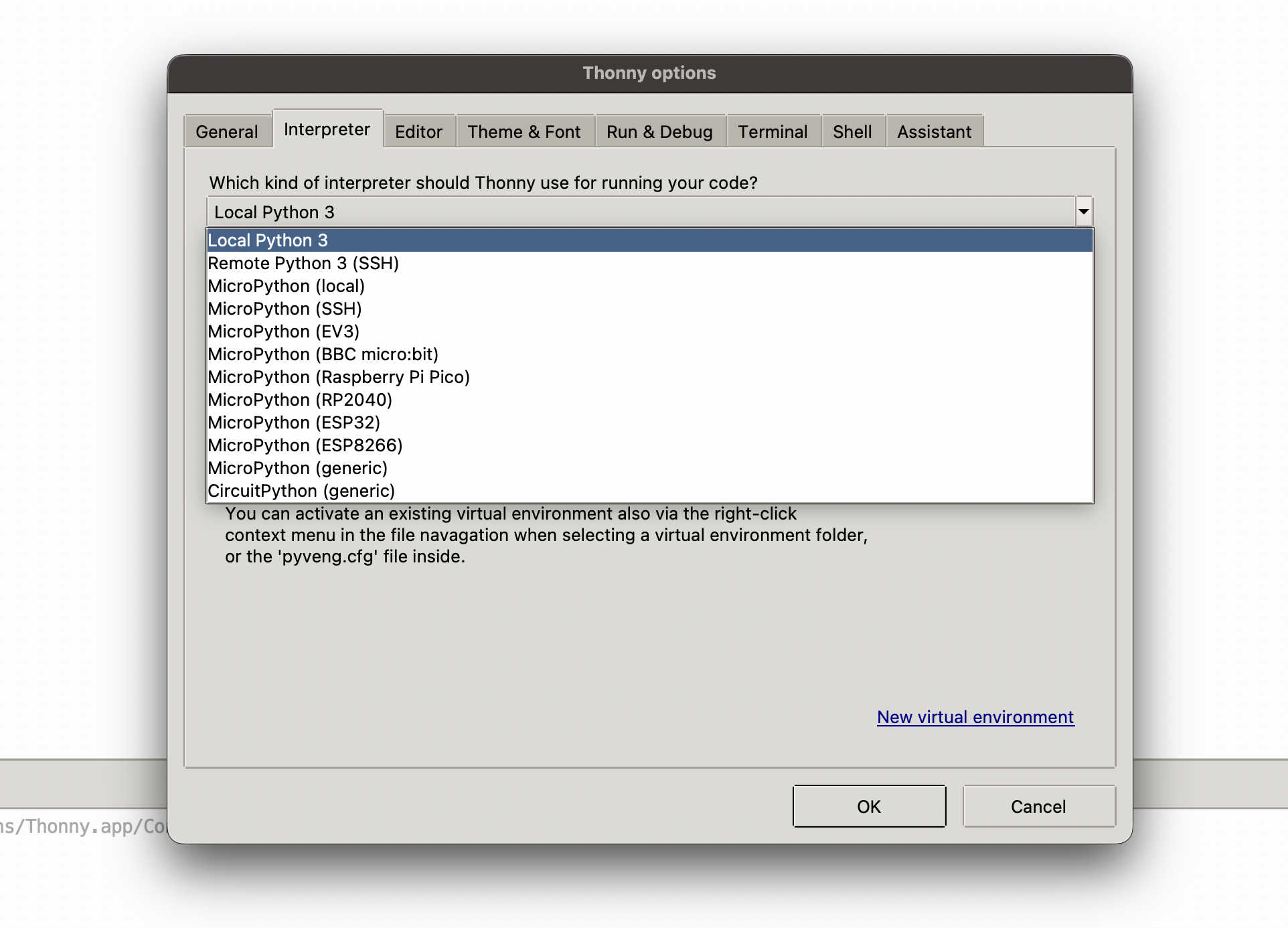
In our case RP2040
Sorry Neil .·°՞(っ-ᯅ-ς)՞°·.
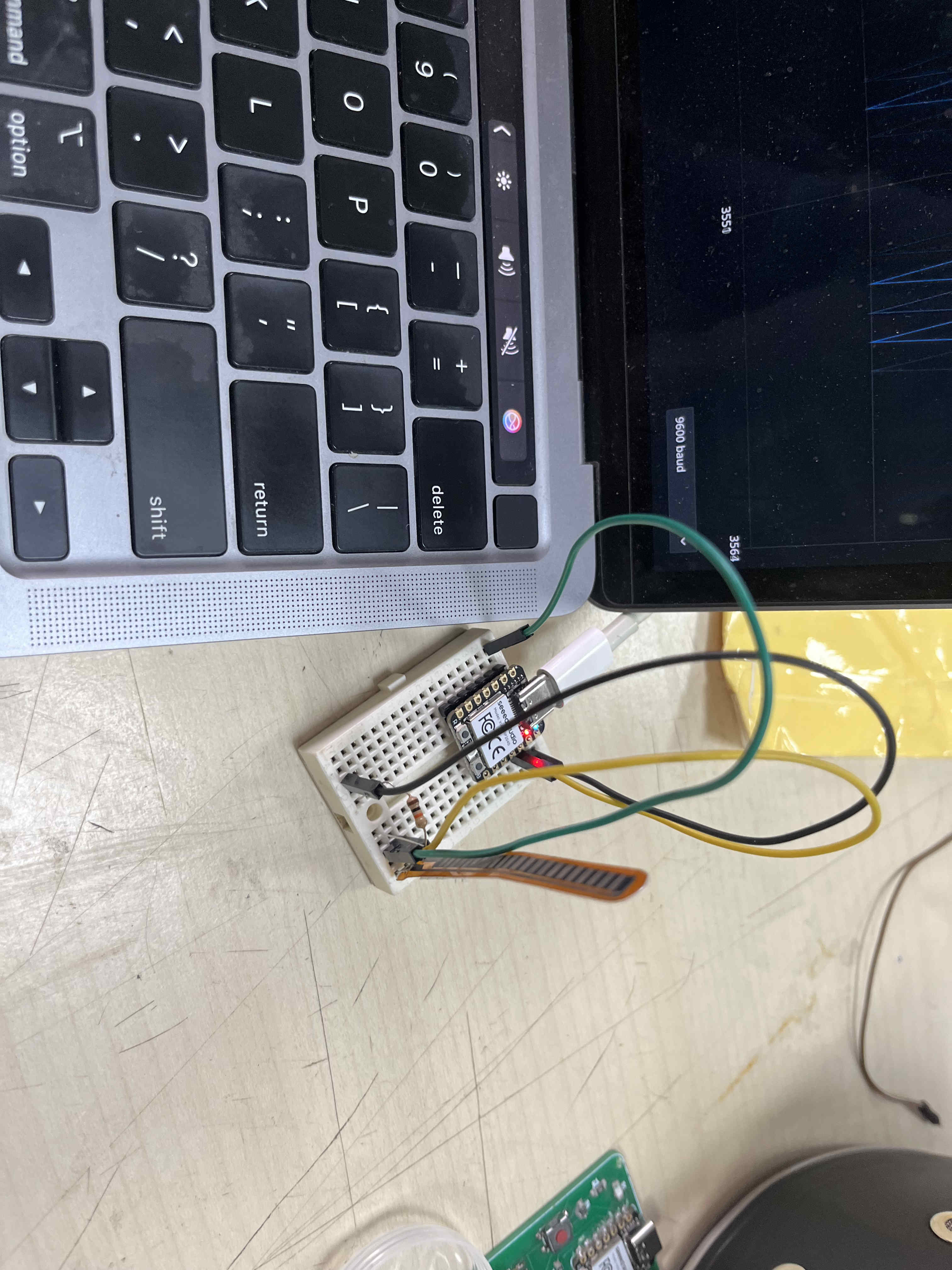
Im using a 10k resistor to filter out noise and get more accurate readings from my flex sensor
There is still plenty of noise in this setup but still a good consistent reading
int flexPin = A0;

void setup() {
  Serial.begin(9600);
}

void loop() {
  int value = analogRead(flexPin);
  Serial.println(value);
  delay(100);
}
Code for the above test
Capacitive sensor
Making my own sensor
So my campus had a collaboration with navrachna labs for which they were making a touc sensitive fabric, using thin copper wire weaved into old and waste fabric
They reached out to us for bringing this idea to life
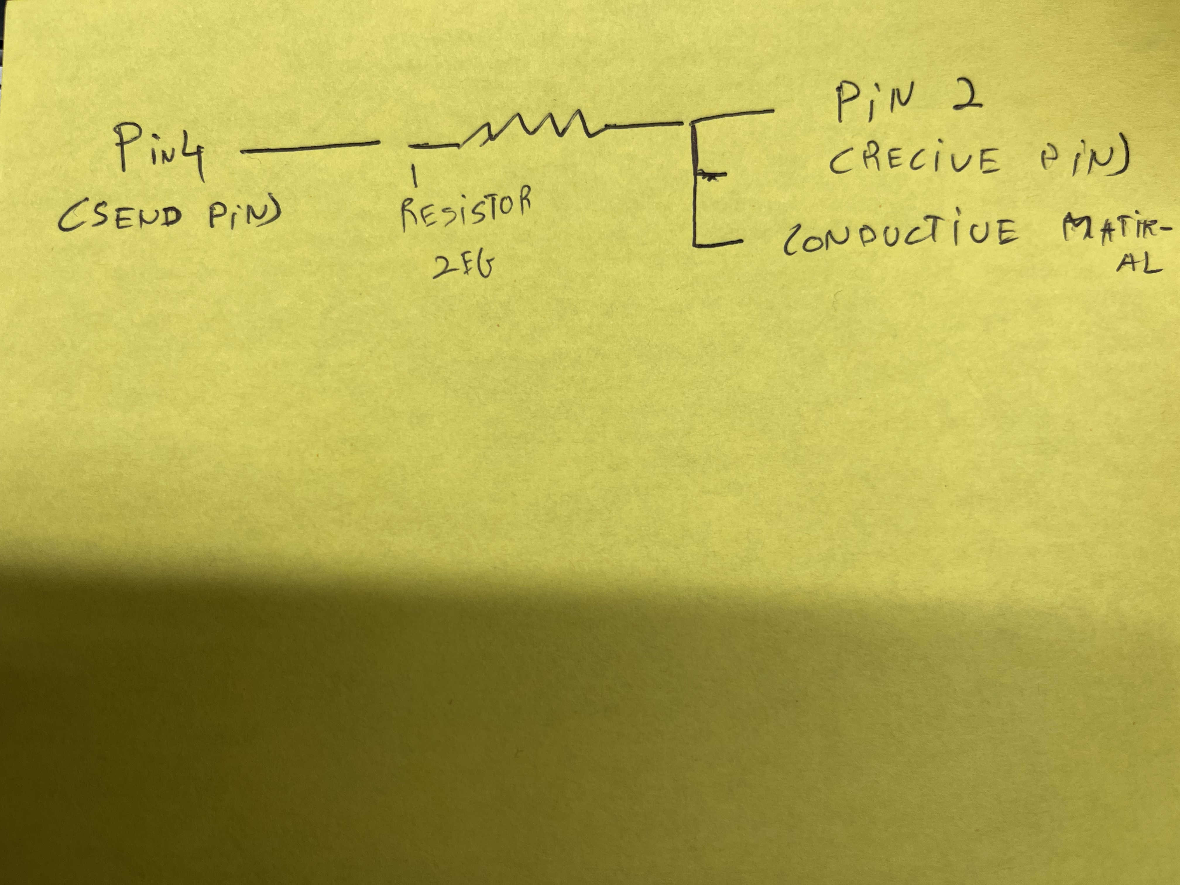
My approach to achieve this touch sensitivity was to read the bodies resistance, when it touches the circuit and give an output based on the readings
#include CapacitiveSensor.h> CapacitiveSensor touchSensor = CapacitiveSensor(4,2); int buzzer = 8; void setup() { Serial.begin(9600); pinMode(buzzer, OUTPUT); } void playTune() { int melody[] = {262, 294, 330, 392, 330, 294, 262}; // C D E G E D C int duration[] = {200, 200, 200, 300, 200, 200, 300}; for(int i = 0; i < 7; i++) { tone(8, melody[i]); delay(duration[i]); noTone(8); delay(50); // small gap = softer feel } } void loop() { long val = touchSensor.capacitiveSensor(300); Serial.println(val); if(val > 500) { playTune(); } else { noTone(buzzer); } delay(50); }Code for this output
#include CapacitiveSensor.h> CapacitiveSensor touchSensor = CapacitiveSensor(4,2); void setup() { Serial.begin(9600); } void loop() { long val = touchSensor.capacitiveSensor(300); Serial.println(val); if(val > 500) { Serial.println("ON"); } else { Serial.println("OFF"); } delay(50);
Code to test if the resistance value set to test is sufficient
Change the if statement to where your readings are stable around
This test gave me a baseline for a few things
Trying with new conductor
The conductor here is a 1 mega ohm which helped me reduce noise alot
#include CapacitiveSensor.h>

// ----------- TOUCH PADS -----------
CapacitiveSensor pad1 = CapacitiveSensor(4, 2);
CapacitiveSensor pad2 = CapacitiveSensor(8, 5);
CapacitiveSensor pad3 = CapacitiveSensor(9, 6);
CapacitiveSensor pad4 = CapacitiveSensor(10, 7);

int buzzer = 13;
int threshold = 500;

// ----------- NOTES -----------
#define C4 262
#define D4 294
#define E4 330
#define F4 349
#define G4 392
#define A4 440
#define B4 494
#define C5 523
#define D5 587
#define E5 659
#define G5 784

#define FS4 370
#define GS4 415
#define CS5 554

// ----------- SETUP -----------
void setup() {
  Serial.begin(9600);
  pinMode(buzzer, OUTPUT);

  pad1.set_CS_AutocaL_Millis(0xFFFFFFFF);
  pad2.set_CS_AutocaL_Millis(0xFFFFFFFF);
  pad3.set_CS_AutocaL_Millis(0xFFFFFFFF);
  pad4.set_CS_AutocaL_Millis(0xFFFFFFFF);
}

// ----------- CORE FUNCTION -----------
void playWhileTouched(CapacitiveSensor &pad, int melody[], int duration[], int size) {

  while (pad.capacitiveSensor(40) > threshold) {

    for (int i = 0; i < size; i++) {

      // Stop instantly if released
      if (pad.capacitiveSensor(40) <= threshold) {
        noTone(buzzer);
        return;
      }

      if (melody[i] == 0) {
        noTone(buzzer); // rest
      } else {
        tone(buzzer, melody[i]);
      }

      delay(duration[i]);
      noTone(buzzer);
      delay(20);
    }
  }

  noTone(buzzer);
}

// ----------- SONGS -----------

// 🎮 Mario (simplified)
int melody1[] = {E5,E5,0,E5,0,C5,E5,0,G5,0,0,0,G4};
int dur1[]    = {120,120,120,120,120,120,120,120,200,200,200,200,200};

// 📱 Nokia ringtone
int melody2[] = {E5,D5,FS4,GS4,CS5,B4,D4,E4,B4,A4,CS5,E4,A4};
int dur2[]    = {150,150,150,150,150,150,150,150,150,150,150,150,300};

// 😄 Fun loop
int melody3[] = {C4,E4,G4,E4,C4,E4,G4,E4};
int dur3[]    = {120,120,120,120,120,120,120,200};

// 🚀 Arcade vibe
int melody4[] = {C4,D4,E4,G4,E4,D4,C4,G4};
int dur4[]    = {100,100,120,200,120,100,150,250};

// ----------- LOOP -----------
void loop() {

  long val1 = pad1.capacitiveSensor(40);
  long val2 = pad2.capacitiveSensor(40);
  long val3 = pad3.capacitiveSensor(40);
  long val4 = pad4.capacitiveSensor(40);

  Serial.print(val1); Serial.print(" | ");
  Serial.print(val2); Serial.print(" | ");
  Serial.print(val3); Serial.print(" | ");
  Serial.println(val4);

  if (val1 > threshold) {
    playWhileTouched(pad1, melody1, dur1, sizeof(melody1)/sizeof(int));
  }
  else if (val2 > threshold) {
    playWhileTouched(pad2, melody2, dur2, sizeof(melody2)/sizeof(int));
  }
  else if (val3 > threshold) {
    playWhileTouched(pad3, melody3, dur3, sizeof(melody3)/sizeof(int));
  }
  else if (val4 > threshold) {
    playWhileTouched(pad4, melody4, dur4, sizeof(melody4)/sizeof(int));
  }
  else {
    noTone(buzzer);
  }

  delay(10);
}
above code is to try all 4 buzzers
Next i thought the buzzer was too jarring, I wanted a more refined sound coming out of the laptop speakers maybe
For this I needed to take the usb modem read it via a python script to play a mp3 sound file when resistance is read as high
Rework
Im trying a pot meter as input using a board i have designed for my final project

this is the board I am using
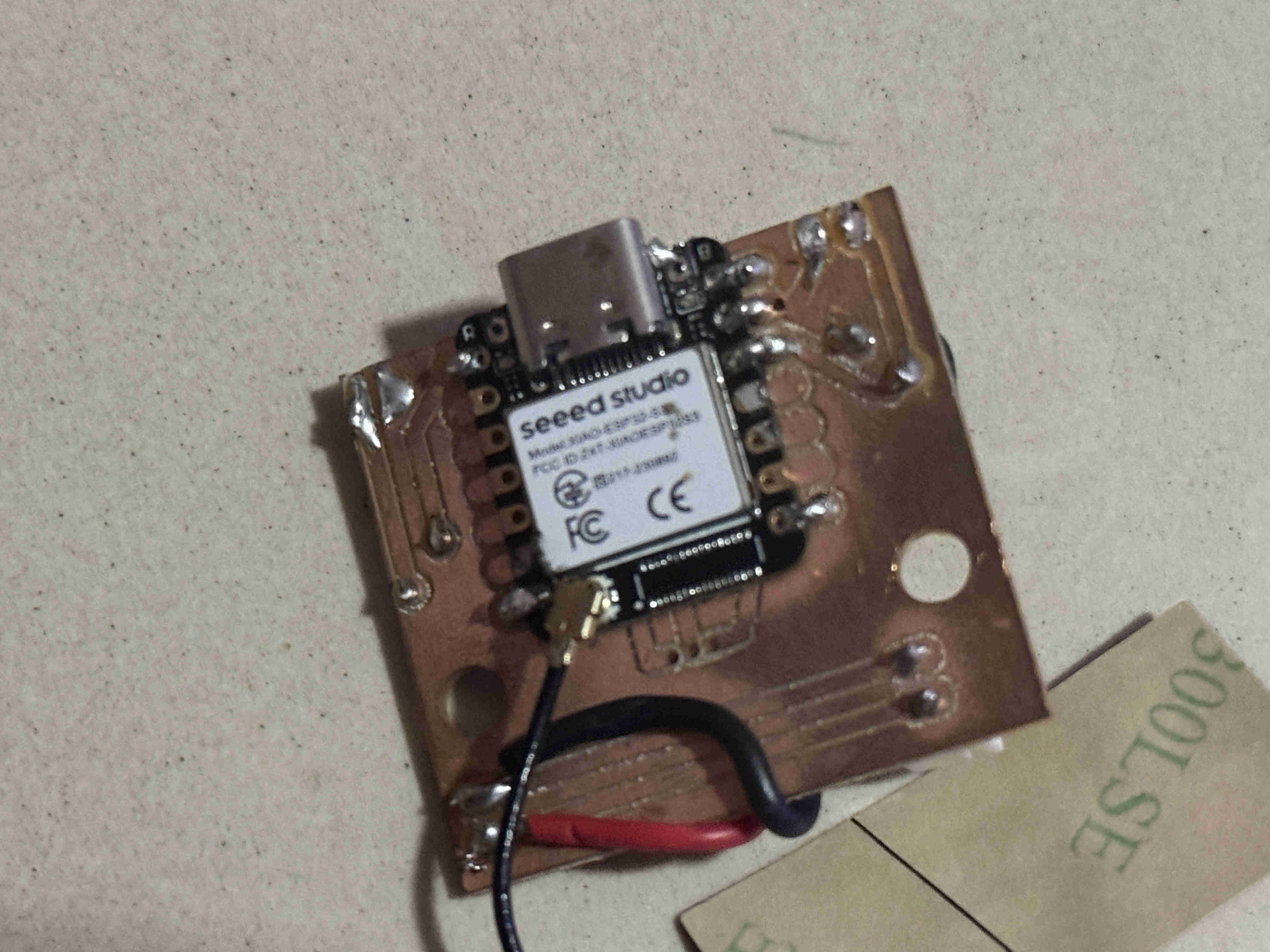
This is the board.
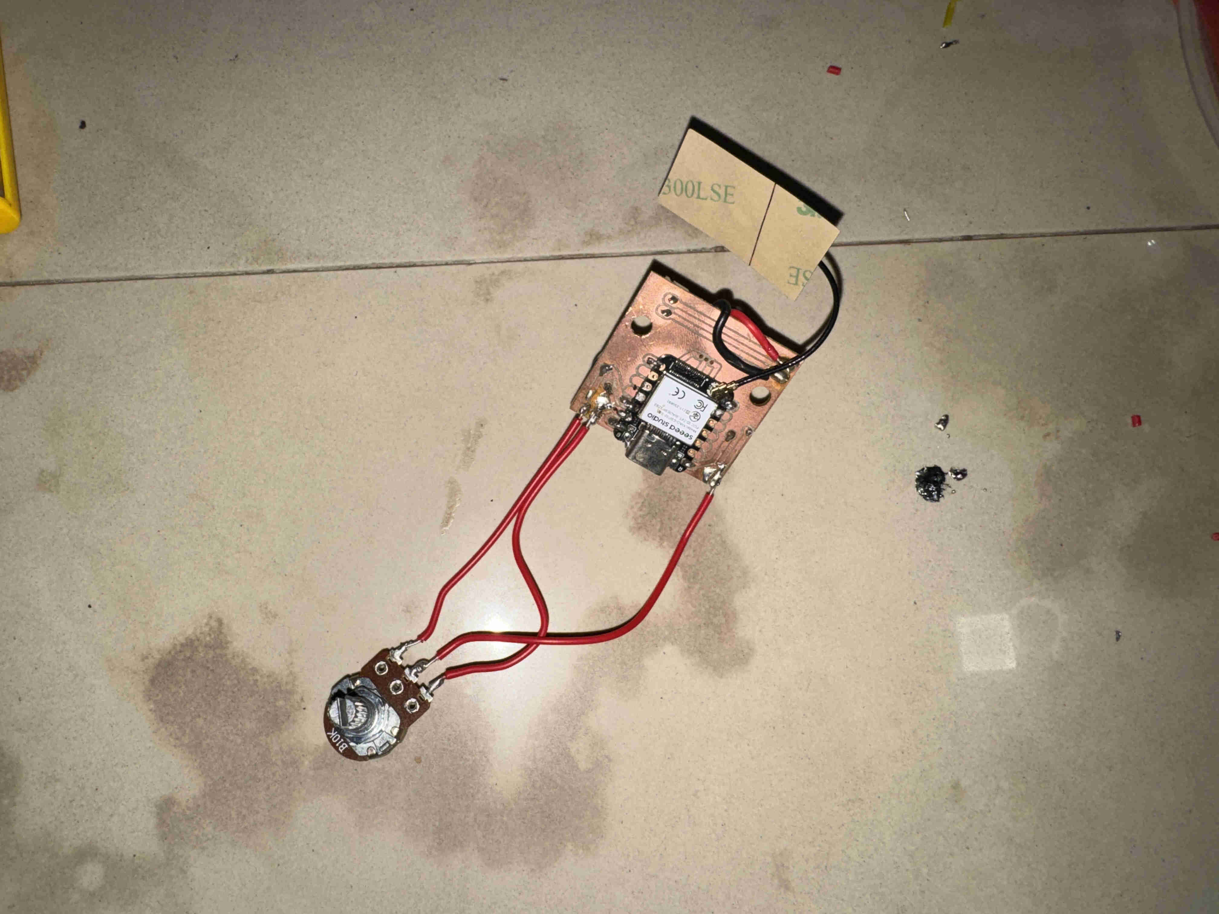
Wire the potentiometer to it as such.
const int potPin = A0;  // free now that NeoPixels are removed

void setup() {
  Serial.begin(115200);
}

void loop() {
  int rawValue = analogRead(potPin);         // 0–4095 (12-bit ADC on ESP32-S3)
  float voltage = rawValue * (3.3 / 4095.0); // convert to volts

  Serial.print("Raw: ");
  Serial.print(rawValue);
  Serial.print("\tVoltage: ");
  Serial.print(voltage, 2);
  Serial.println("V");

  delay(200);
}
Test code for pot meter.