3D printing is always exciting, to watch something being built layer by layer right in front of your eyes is absolutely mesmerizing, the possibilities one unlocks with a machine like such is immense,
However 3D printing is treated more and more as alternatives for finished products. As a product designer with a certain OCD with finishes, this doesn't sit right with me
In my exploration for this week I put my 3D printer to do jobs That ONLY a 3D printer can do.
Understanding .gcode
What is it
If you have ever 3D printed you might have some idea as to what a .gcode is.
To put it simply, gcode is a alphanumeric set of instructions that can communicate with your 3D printer regarding
Rapid movements - Indicated by G0
Precise movement in coordinate directions - Indicted by G1
Set extruder temp - Indicted by M104
Origin set - Indicted by G92
Bed temp Set - Indicted by M140
Pause and stop commands - Indicted by M0 & M1
And many more set of commands controlling various aspects for a FDM print to come to life
Since a FDM print mostly needs nozzle head moving to specific coordinates, G commands are the most common in lines of .gcode, thus the prevalent name For starters i wanted to see a live gcode created by my slicer
I imported an old stl just to read through the generated gcode and interpret it, now that i understand commands a little
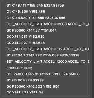
As you can see, various alphanumeric commands
I read through a few lines roughly understanding whats going on
If i wanted to control my own gcode, understanding what a correct working one was crucial
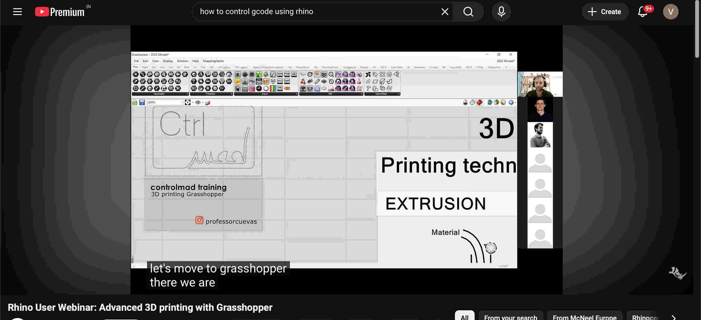
The software is an old outdated creality print software, you can use many slicers like orca, ultimaker and morehttps://youtu.be/2fqDubW4t5I?si=ITK-Z_dBSkdkXYrIAbove is a consice video explaining gcode.https://youtu.be/OE_daHEf1MM?si=PUP1JbDN3juhq6SyNext i started by trying to create my own gcode using grasshopper
Above link is a free youtbe tutorial led by a industry leader in non-planar printing
Non-planar printing
Non-planar 3D printing is an advanced technique where the print head moves in all three dimensions (
𝑋, 𝑌 and Z
) simultaneously, allowing material to be deposited along curved, contoured, or sloping surfaces rather than just flat, stacked horizontal layers. This approach improves surface quality, increases strength, and reduces support material.
This is extremely cool because if you master this, your prints can come super smooth with minimal layer lines, and structures that are far superior
The printer im using here is a Bambulabs A1.
https://bambulab.com/en-in/download/studio
Here is the link to install the bambu propritery software
The bambu labs a1 is an amazing affordable and reliable printer.
The a1 is a non enclosed, bed slinger which makes it not ideal for taller prints and materials like abs. but does a good job for most prints and filaments.
Specifications
Bed size- 256mm x 256 mm x 256 mm
Max speed- 6000 mm/s
stock model does not come with a hardened nozzle.
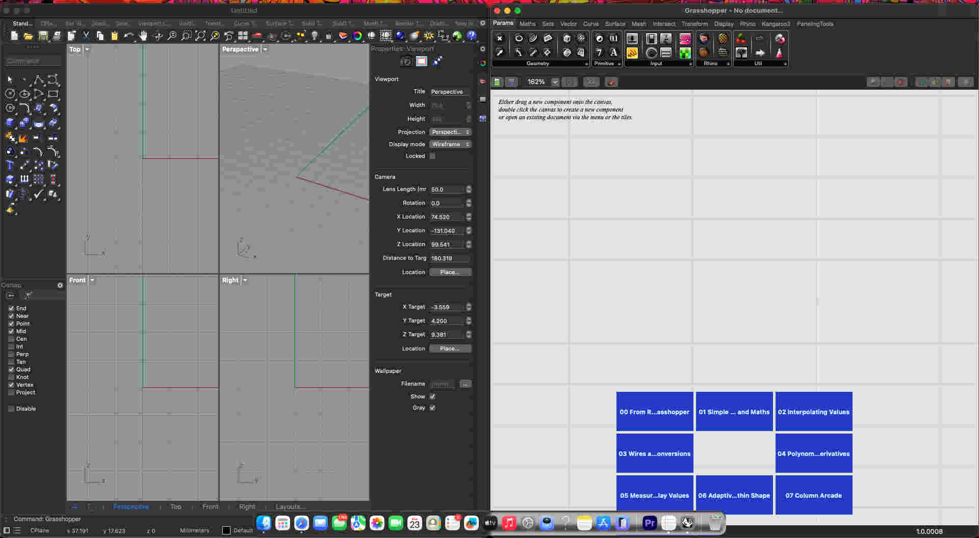
Let's try out our own g-code on rhino
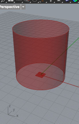
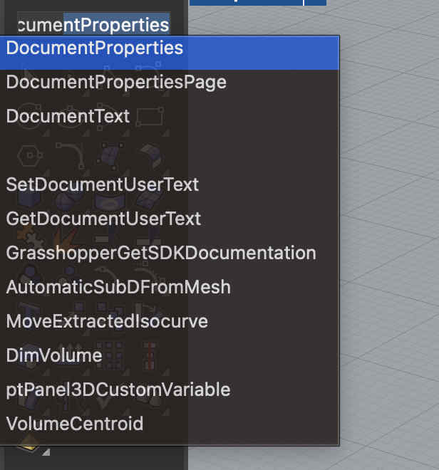
I recommend using your tabs as Seen.In grasshopper you can press space or double left click to search for commandsFirst we make a basic cylinder of certain height and diamter in grasshopper Commands
Cylinder
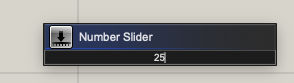
panel- set value for height
Connect respective panels on height and dia
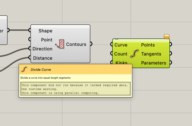
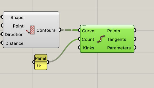
Now we need to devide this surface type structures into curves/ paths that the tool can follow
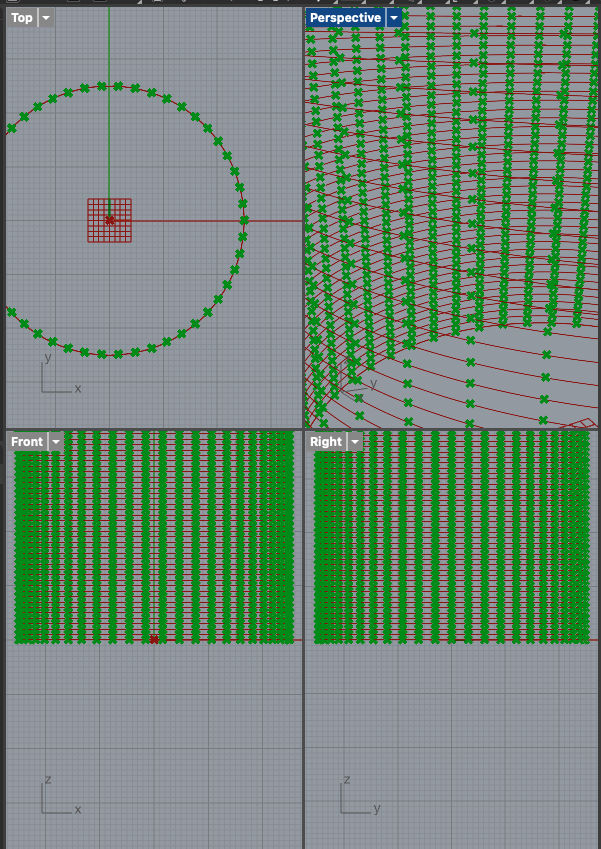
You can do so with the divide curve commandResultThen we divide each curve into a set value of points to act as xy and z co ordinatescommands
Divide curve
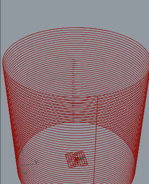
Result
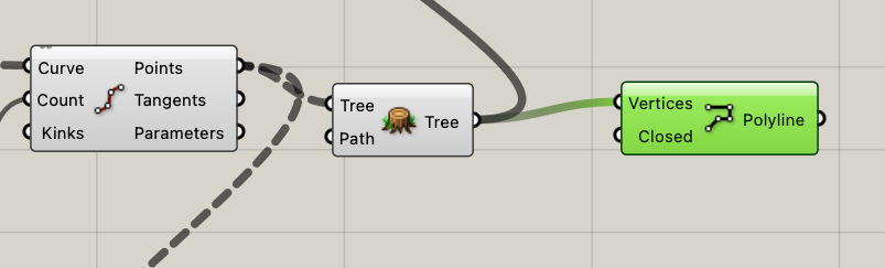
now we need a polyline
a continuous curve extending throughout the cylinder
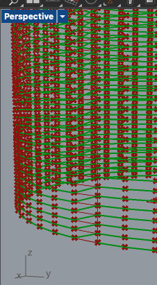
We can make a tree of the previous curves and feed it into a polyline commandResult
Now we can take x,y and z co ordinates of each point and polyline,
add other elements of extrude amount, speed, origin.
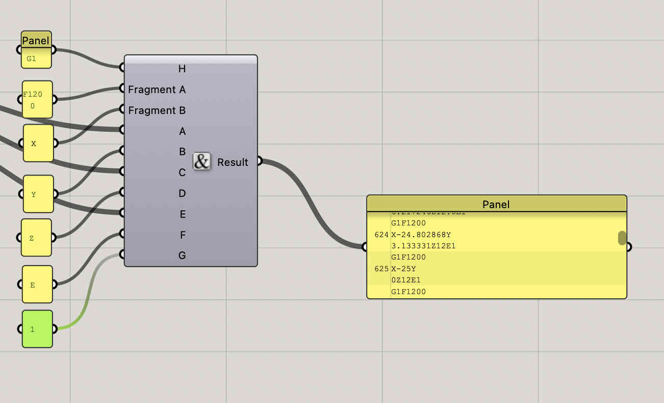
Concatenate them all, and voila
Something like this
Each panel on the left indicates a a postion or a code, the result panel takes values from co ordinates and merges both to create a aphanumeric file.
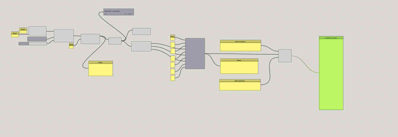
This is a sample grasshopper, real code will have many more factors
Remember- What we have done till now only sets the working protocol, the start and end still have to be defined
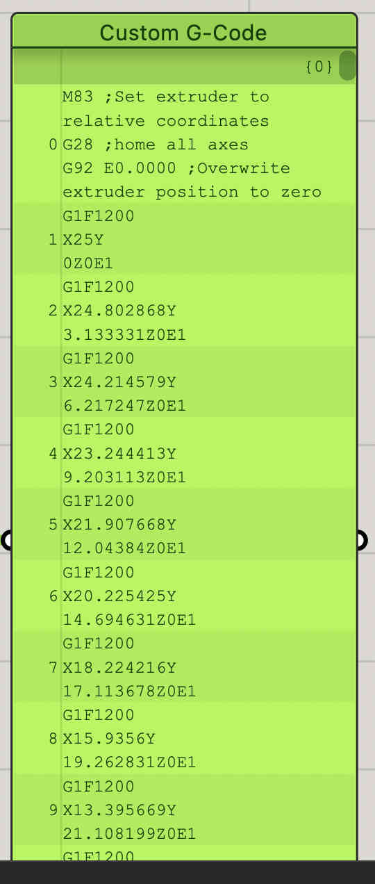
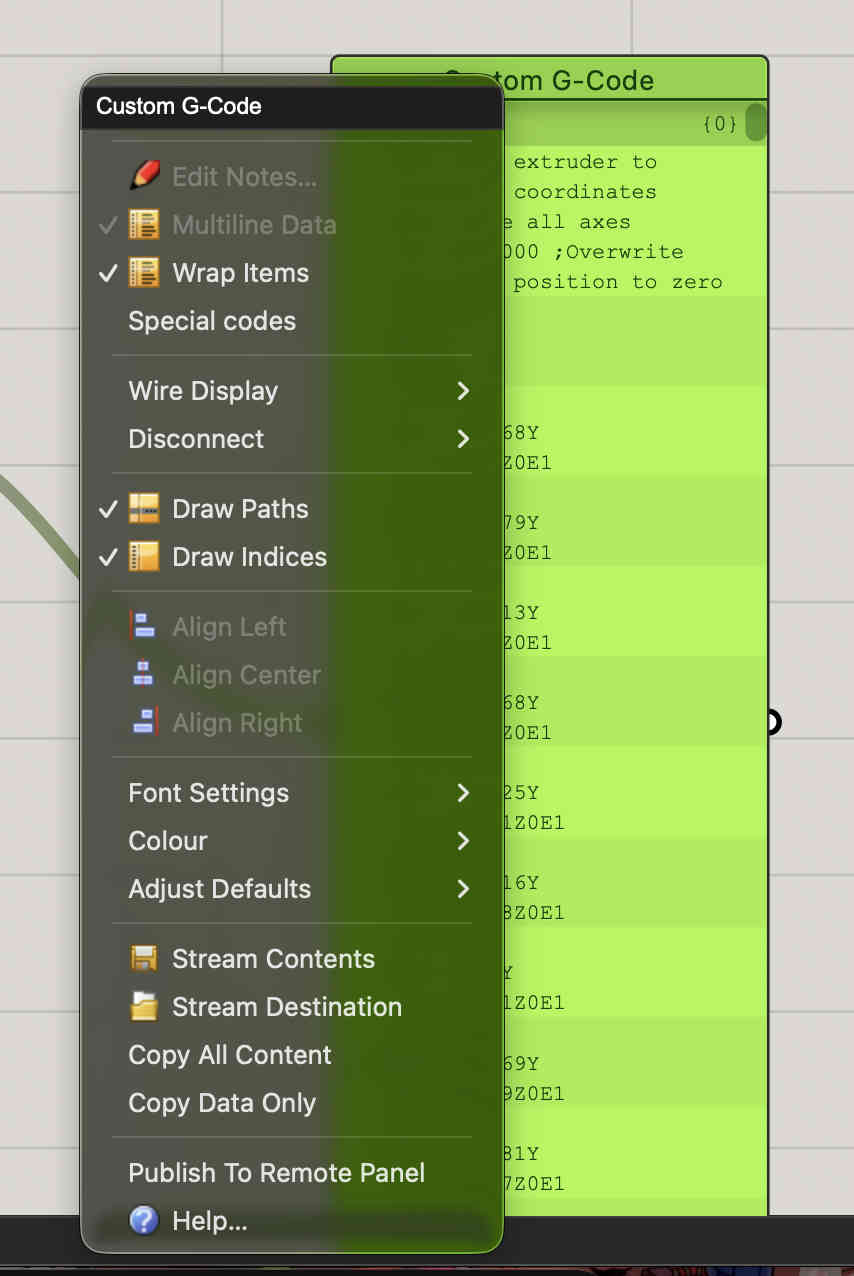
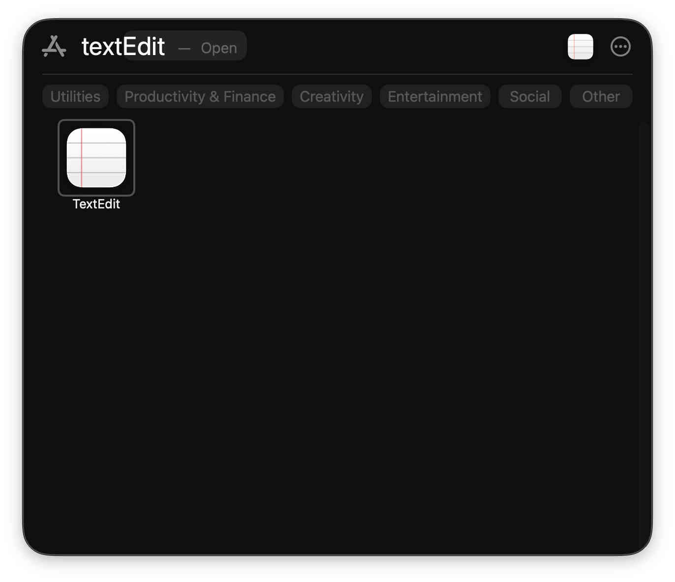
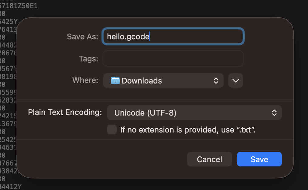
On the right side of the screen you can see the result being seen on a panel. and i have also set a start protocol and an end protocol which i then bring to a final panel creating a g codeA basic gcode for a cylinder is ready.Right click and COPY DATA ONLYPaste the text onto the most complex software of all time- notepadExport it as .gcode, remeber to untick .txt default saving command
You can now open this gcode on any slicer and your model should appear
I faced some error while trying it on my prsonal printer and slicer, mostly becasue of a missing parameter in grasshopper. I have kept it aside for now and will try again soon
.Wireframe modeling using blender.
Next i tried to create a tesseract type structure using wireframe modelling
As a wireframe model is not manufacturable, this was my backup safe print to complete my assignment, and then I can move onto exploring more.
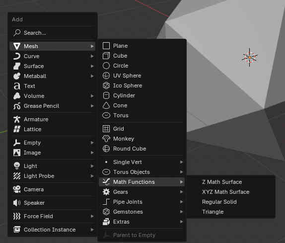
First we create a icosohedron using math funtions in blender.
Commands-
Shift + A to add
mesh- math funtions- regular solid
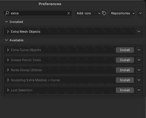
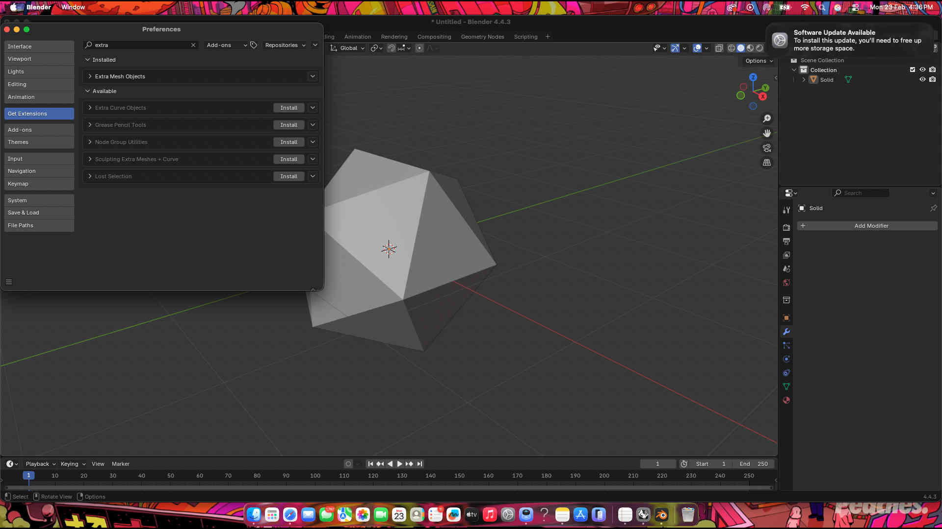
If you don't find math functions, you can add it manually using add-ons on prefrences.Your icosohedron should appear We now use modifiers to create our shape.
Wireframe modifier
more modifiers
bevel modifier
Subdivision surface modifier
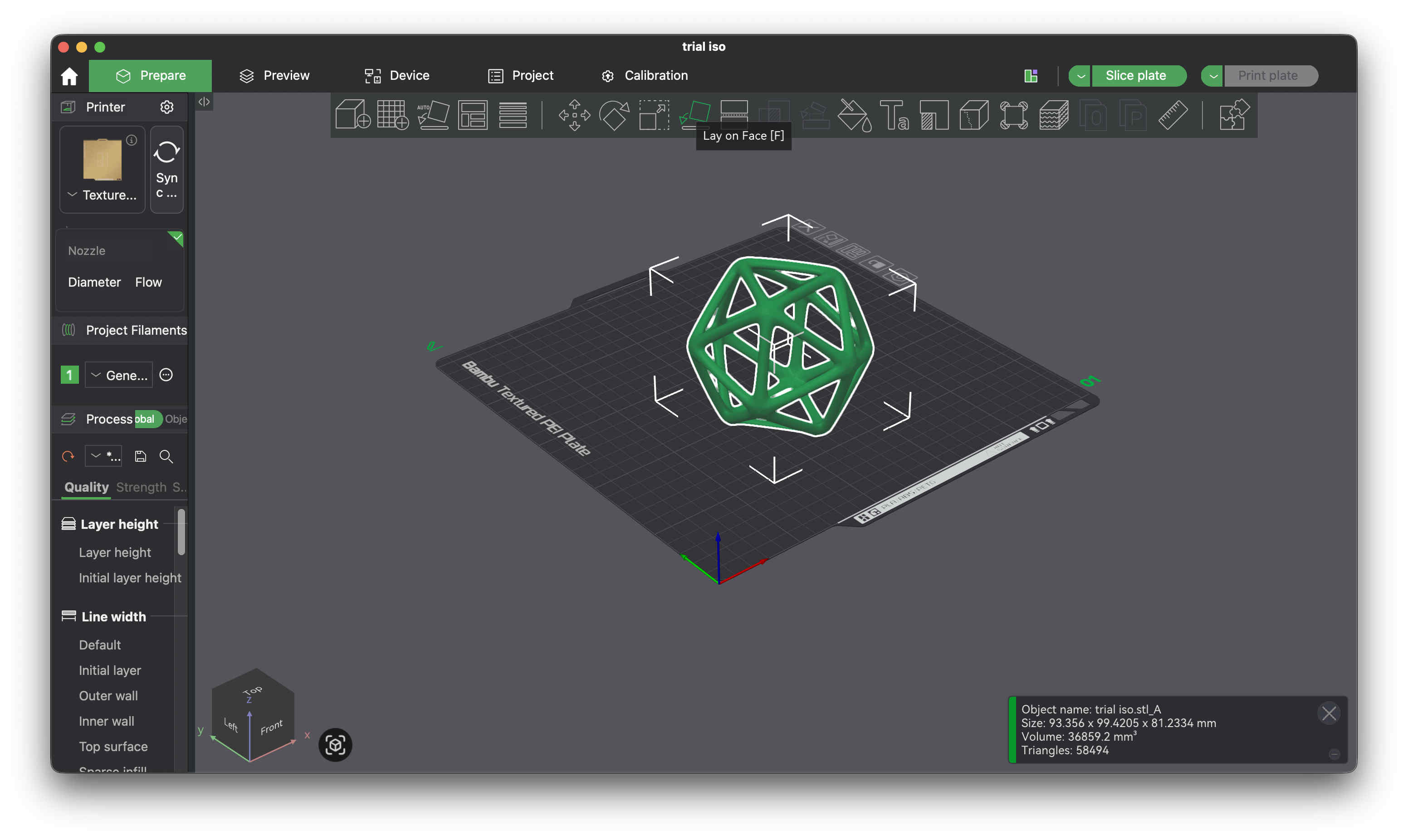
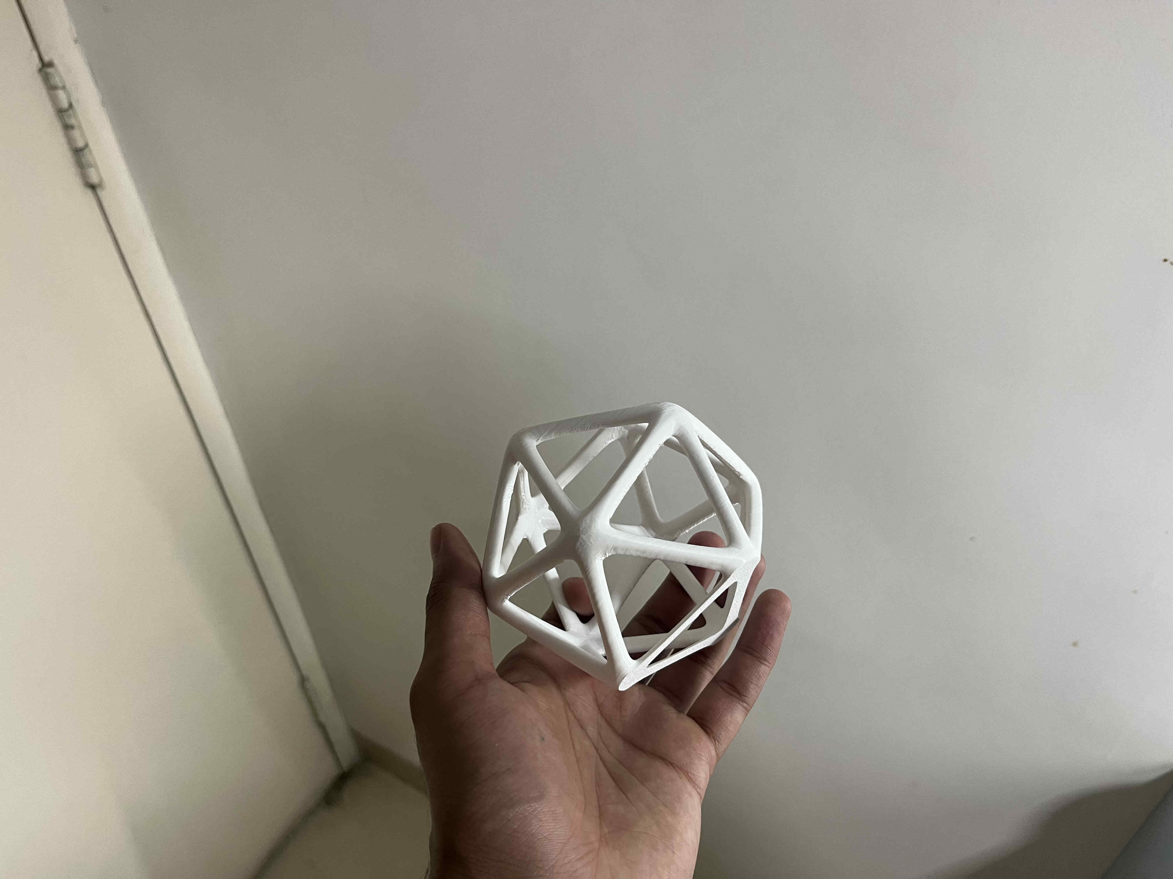
Remember to apply your modifiers Wireframe icosehedron is ready Modify your thickness well. thinner structures like this that are curved at the bottom won't stick well to the bed plate. causing the print to failImport STL to your slicer You can take help of the automatic lay on face option, to make one side of the model completely flat to the bed plateFor the sake of preventing brims and print quality i chopped 3 mm of the bottom section to make it flat.
(and hoped to god it does not come off the plate while printing)
.Brim.
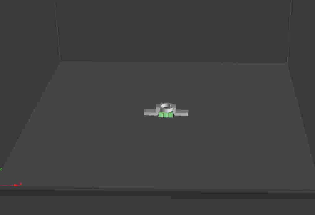
A brim in 3D printing is a flat, single-layer border printed tightly around the base of your model. It acts exactly like the brim of a hat, giving your print a wider, sturdier "foot". This increases the surface area touching the print bed, keeping the edges glued down.
Exactly as seen in the picture above, a brim adds contact are on the bed(green part). This is ideal for prints with a lower surface area, as printing without brims might cause the print to just loose adhesion and fall off midway of the print.
You can take help of the automatic lay on face option, to make one side of the model completely flat to the bed plate
Result
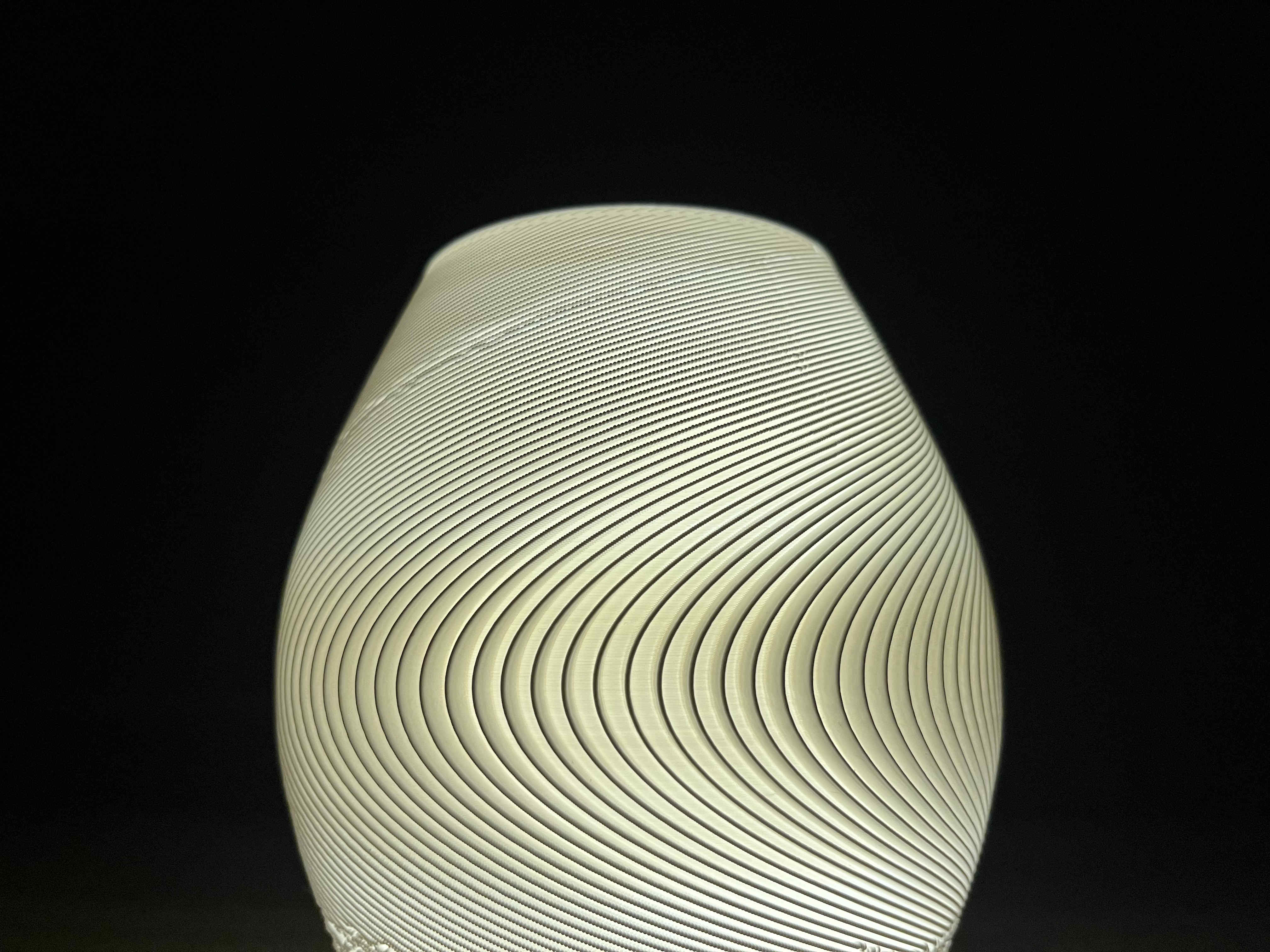
.Modelling that can be used ONLY on FDM.
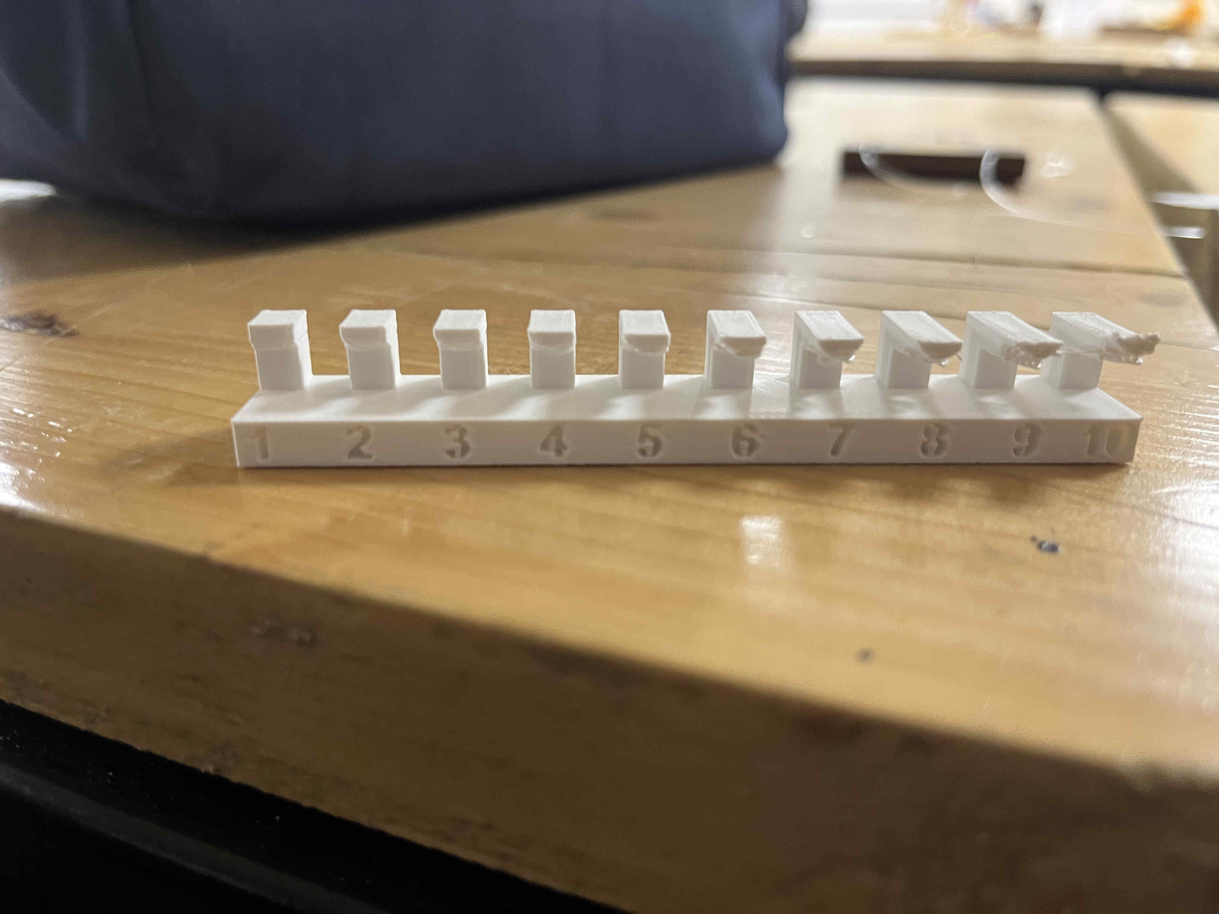
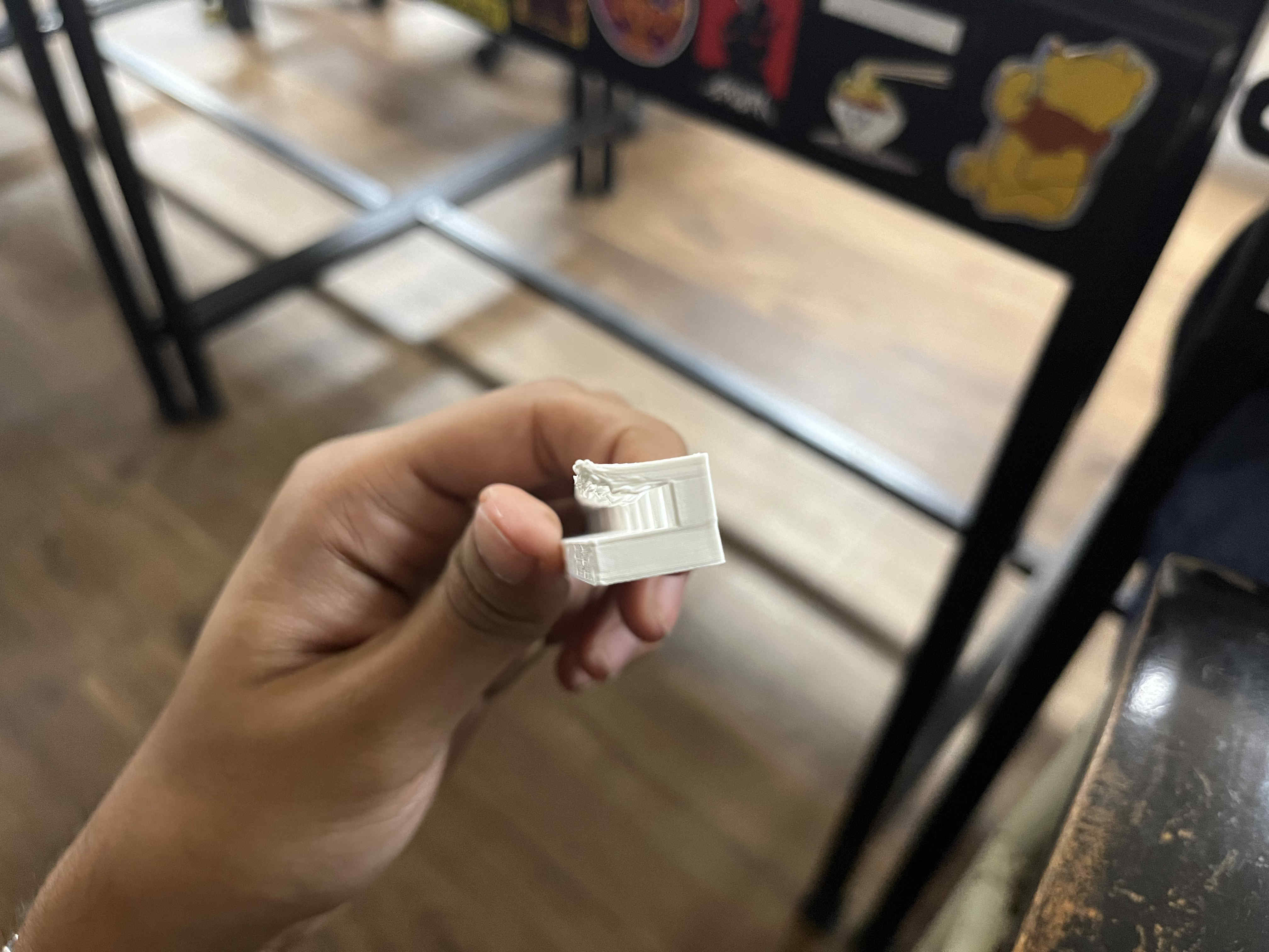
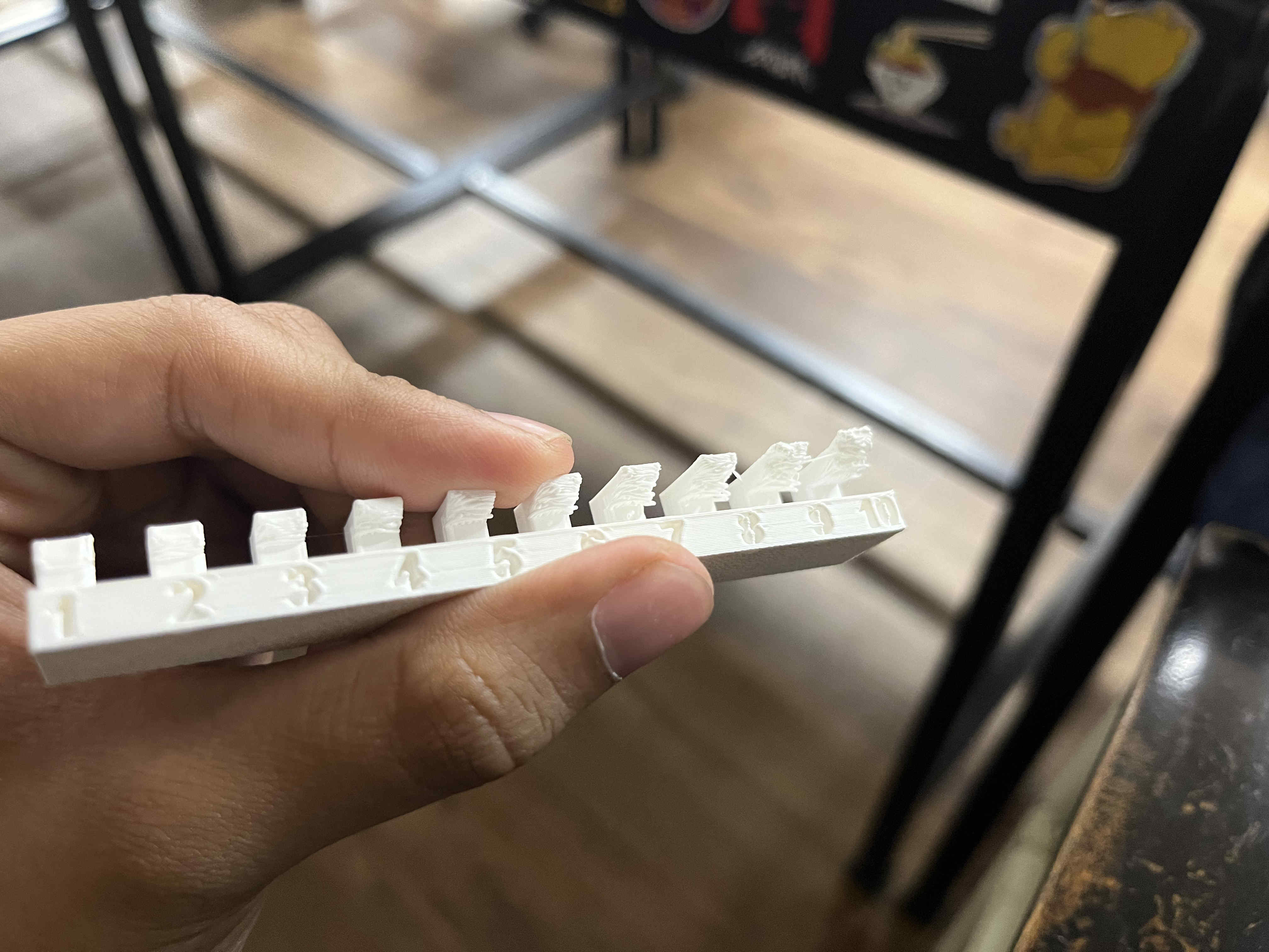
Before i started this, it was important to know my printers max possible overhang angles, as my print with complex structures wont have supportsThese were at max speed (300m/s ) 15 percent infill and on a bambulabs A1 printer
I tried setting the fan at 100 percent for the entire print to cool down plastic quickly
Lets jump to modelling now
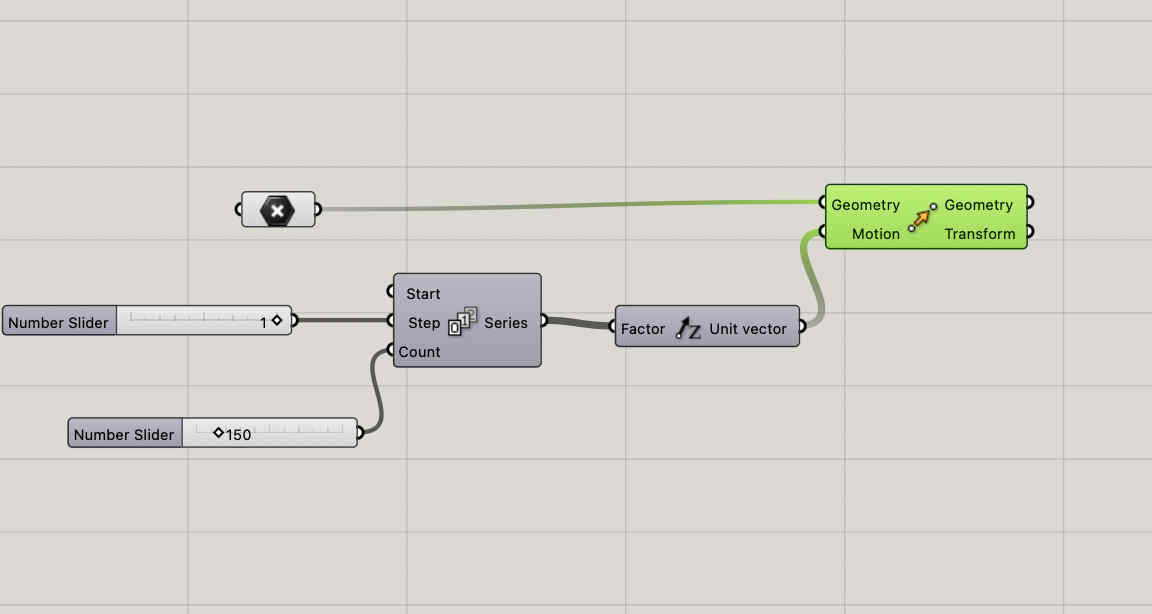
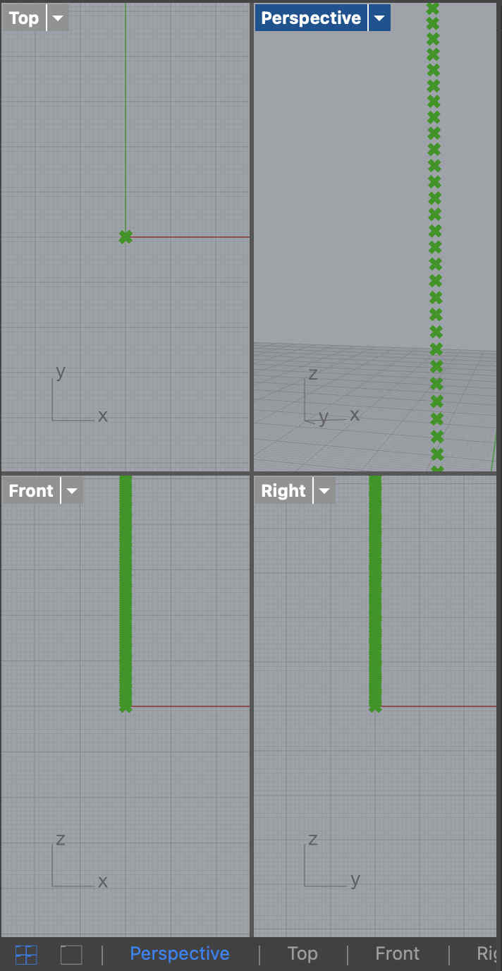
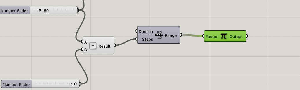
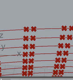
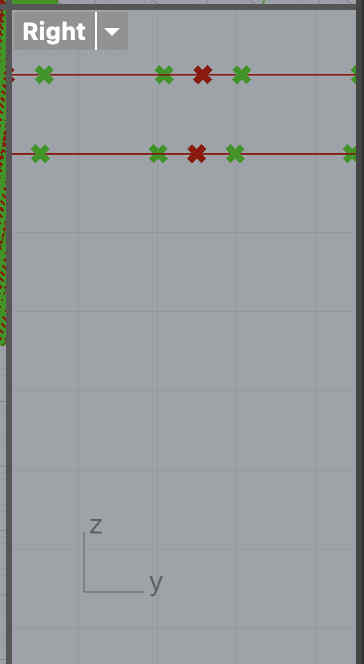
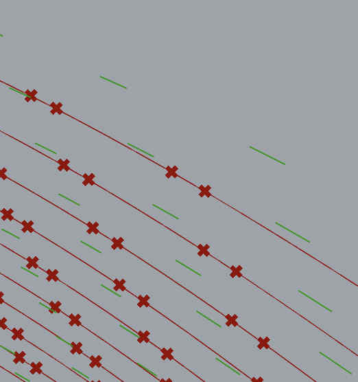
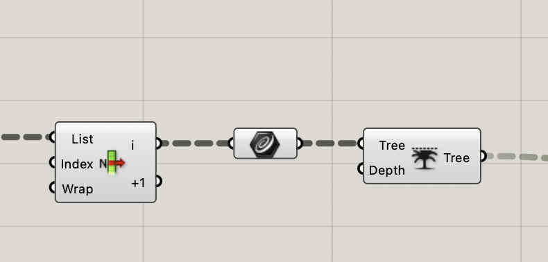
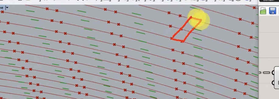
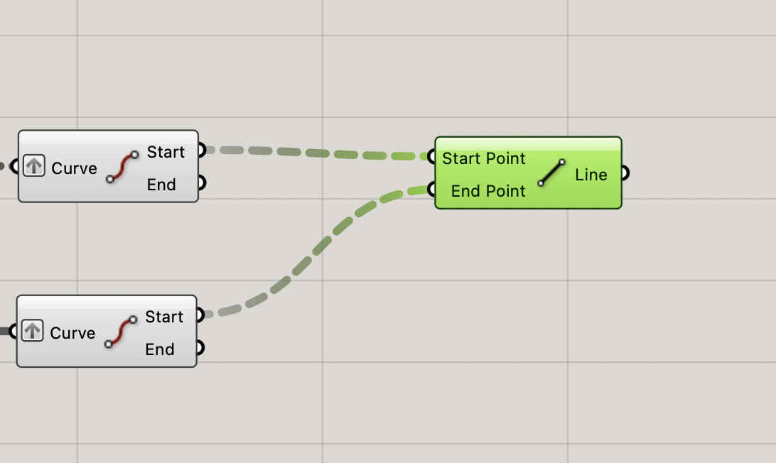
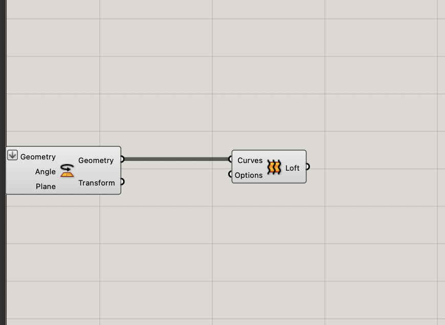
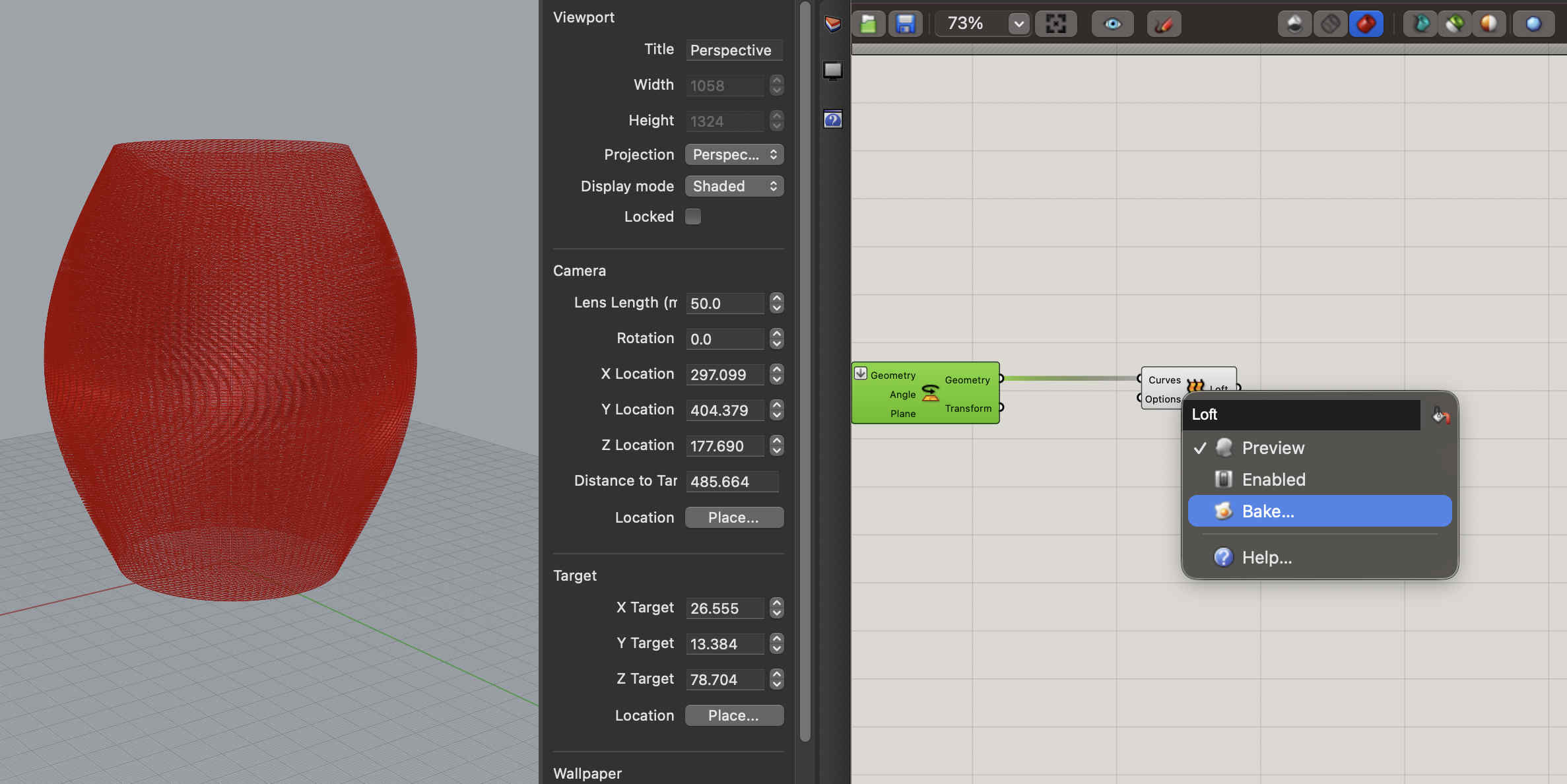
First we open rhino and set our document properties to mmWe plot point's at the center, of the grid, 150 point array. the grasshopper looks something like thisResultNow we need to create circles with our points as centresOnce we do that such lines should appearAlong those dots, we need to create more dots at a certain distance so that we can create ridge like structuresWith these new dots we can offset lines which we can join later to create gear like structures in an progressive mannerHere we create a offset of the segments created by the dots as seen in the previous oic Now we need to bridge the two segmentsWe cross connect start and end segments that we take into a curve module by nesting all togetherResult, you can see how the lines no connect with each otherNow we take all geometry into one module, such that we can loft the structuresAlmost thereBake your loft into blenderBaking might take time but VOILARemeber to lock all your grasshopper commands that are computationzlly heavy, they will cause issues on restart, also hide themResult
Exporting
Export using stl with the same check boxesRemember to go to detailed export and switch to smnooth and slow and untick jaggered seamsI have not documented every single detail to create but rather major steps. to create follow along the listed youtube video
.Slicer.
Once we have our model we can import it into our selected slicer
im using bambu studio
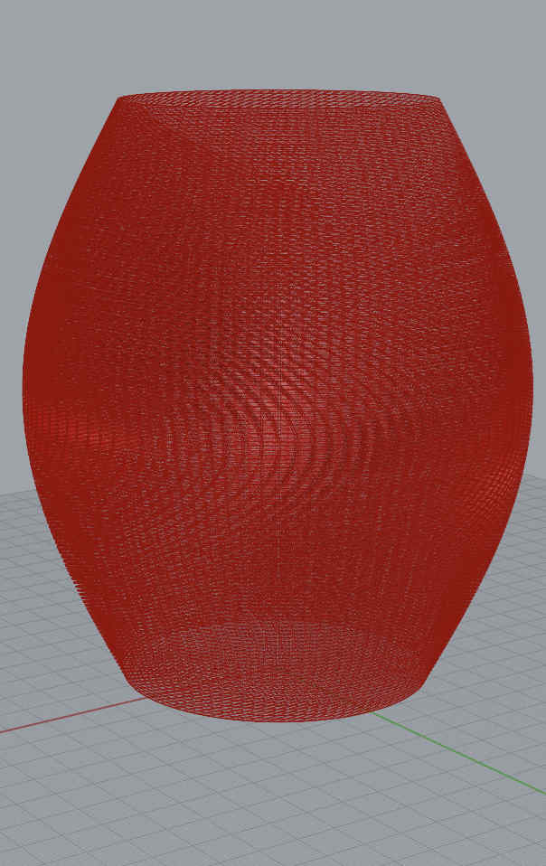
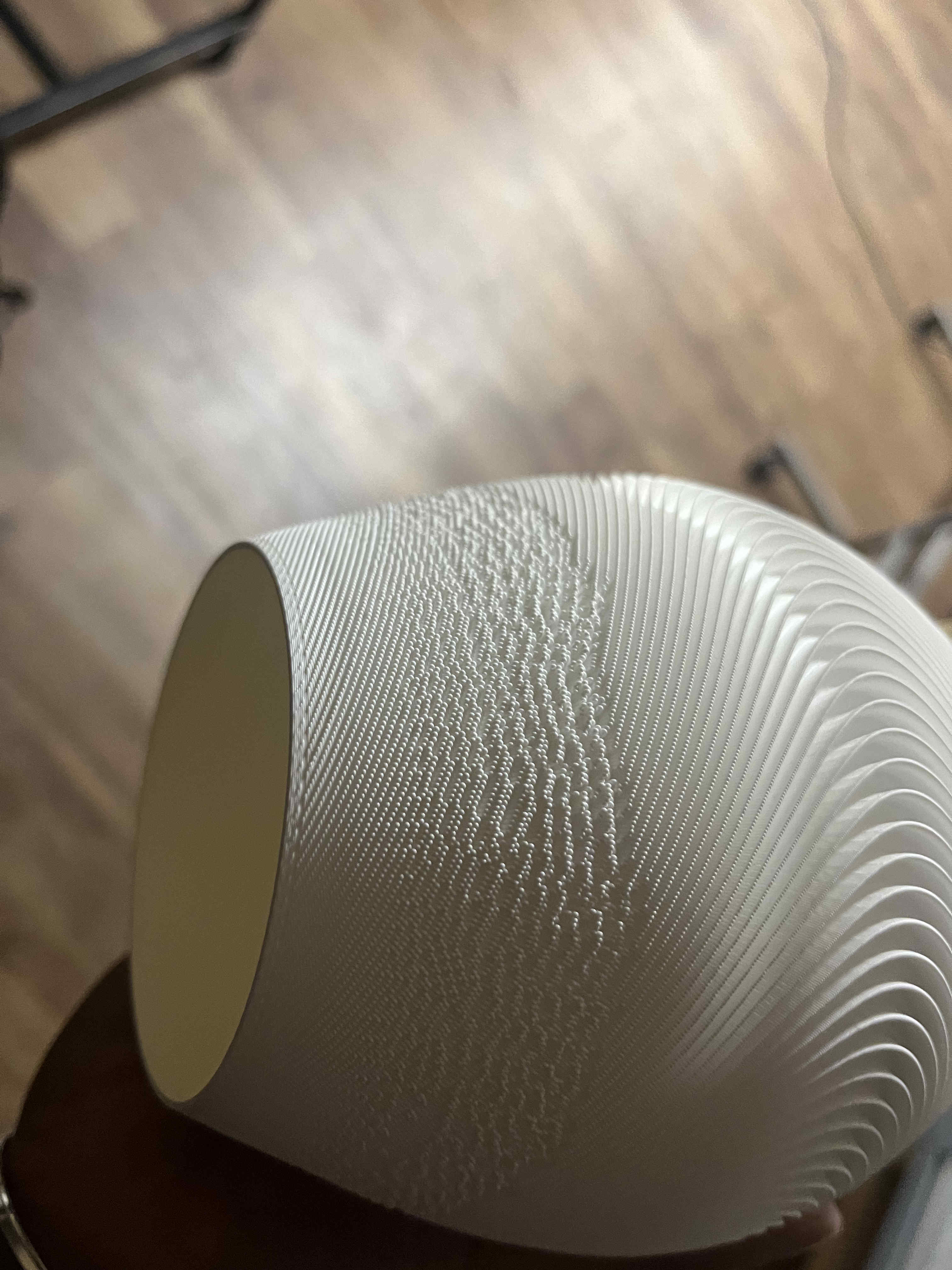
While i imported the model, the preview seemed correct, butMy sliced model was FILLED and had NO textureI realised that the issue was in my slicer, where top layer was set to 5, causing the entire structuire to get filledonce i bought that to zero, issue solved.The texture absence was due to an export error, and the fill was due to slicer, keep all ends tight while you make complex structures
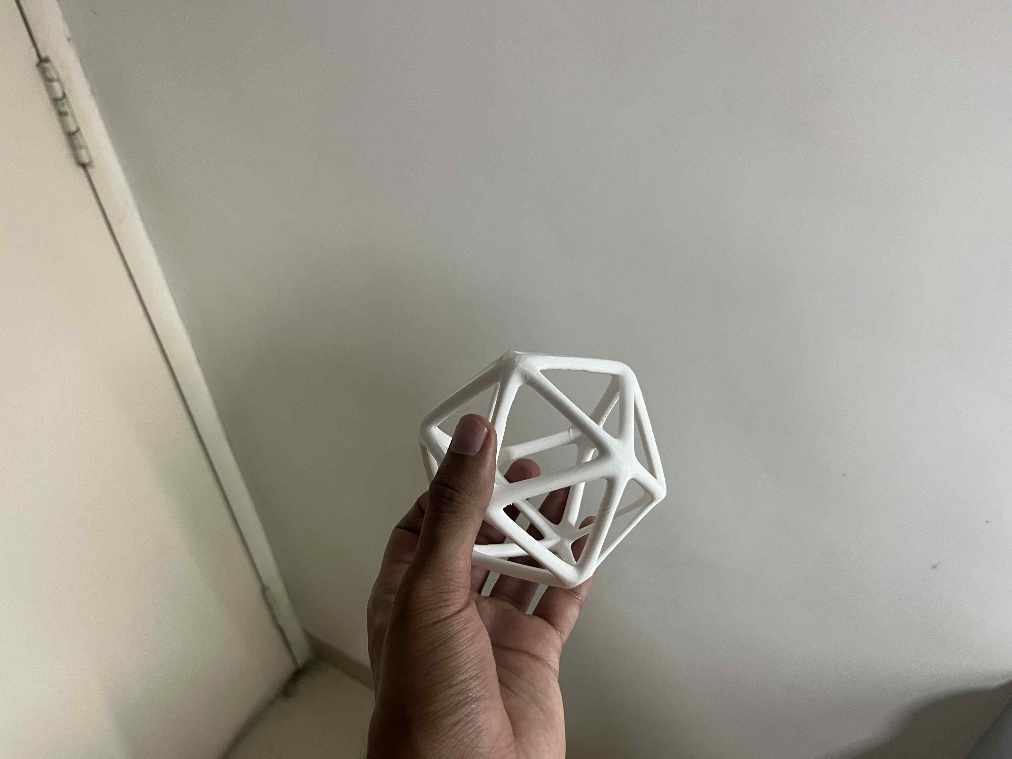
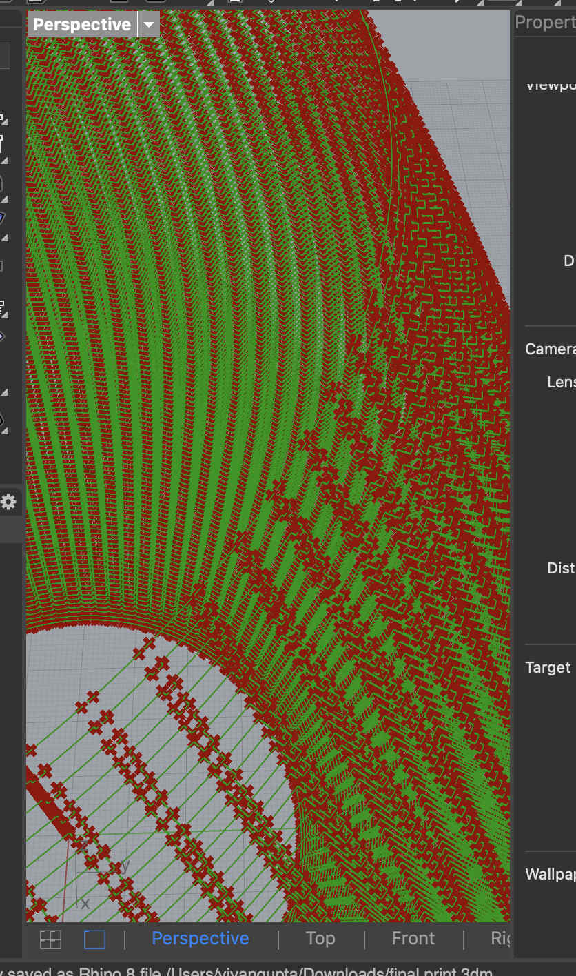
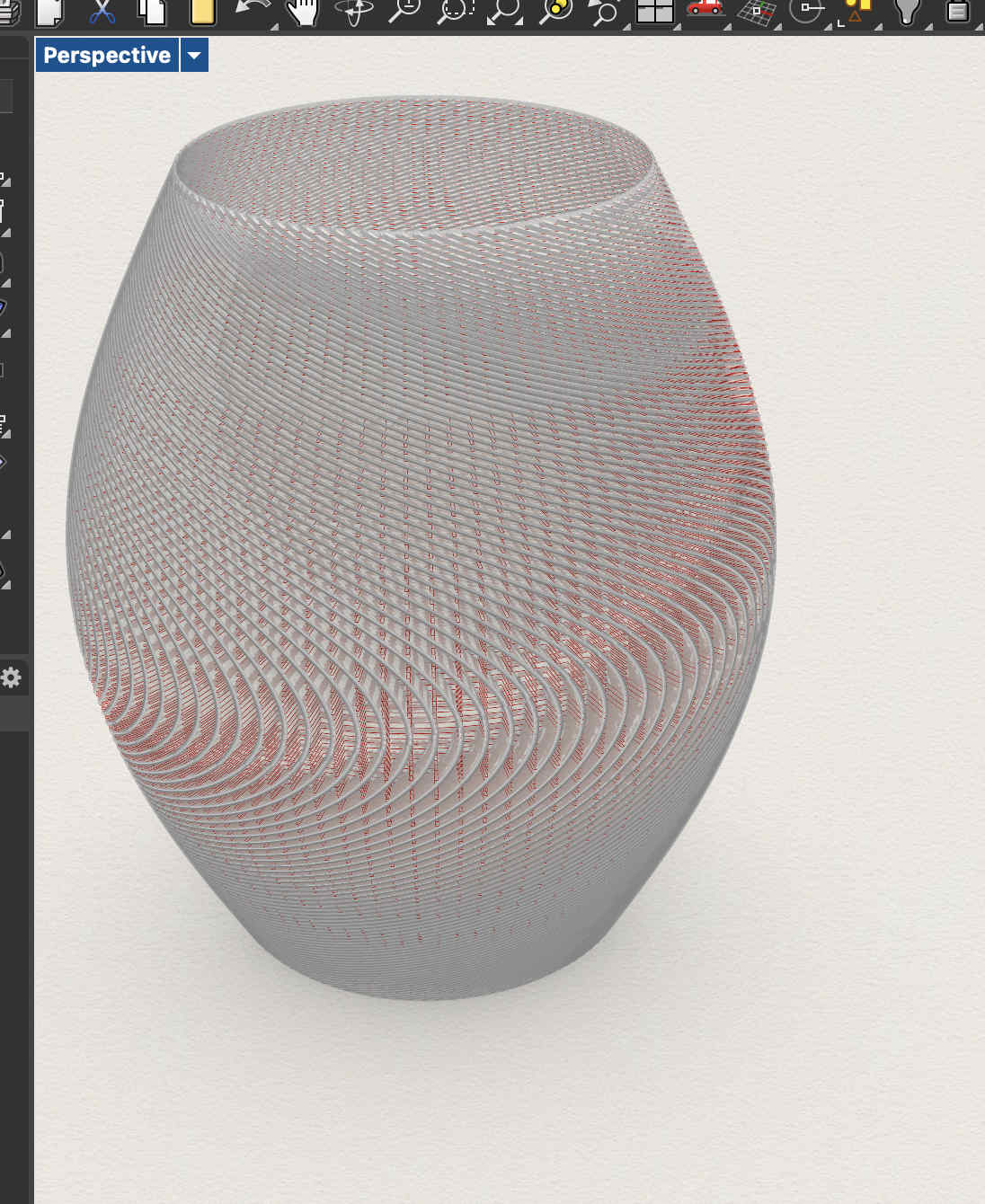
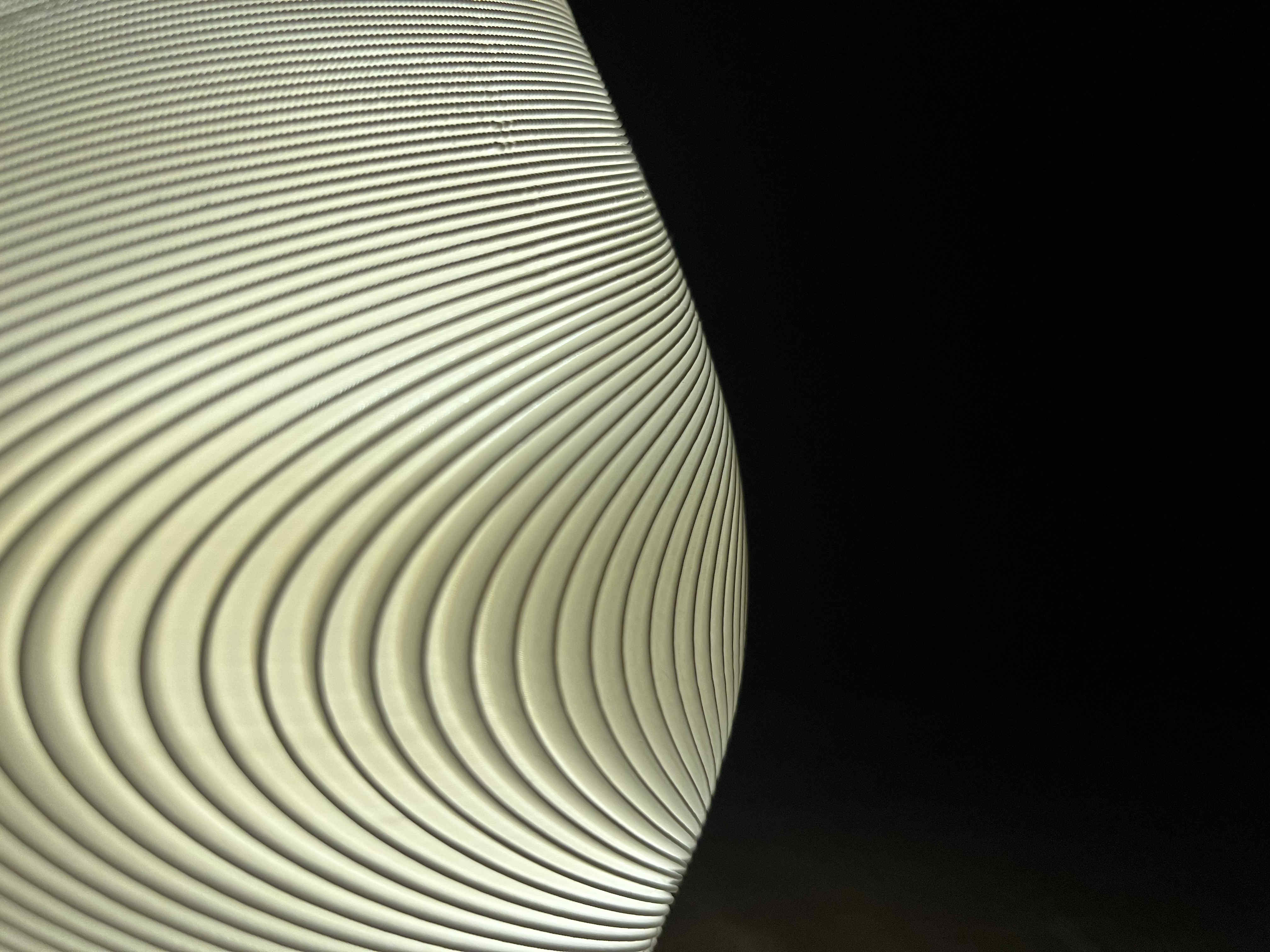
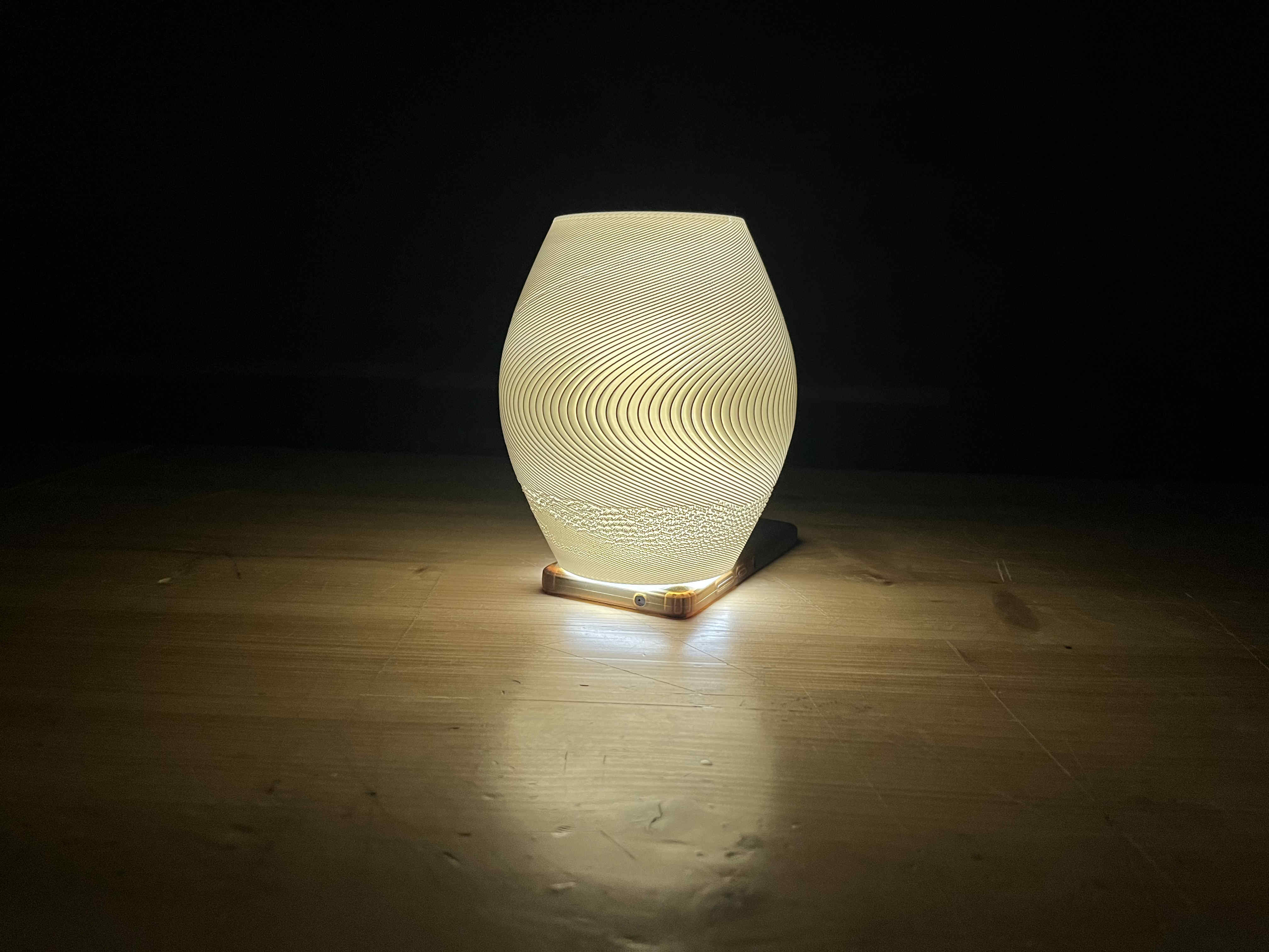
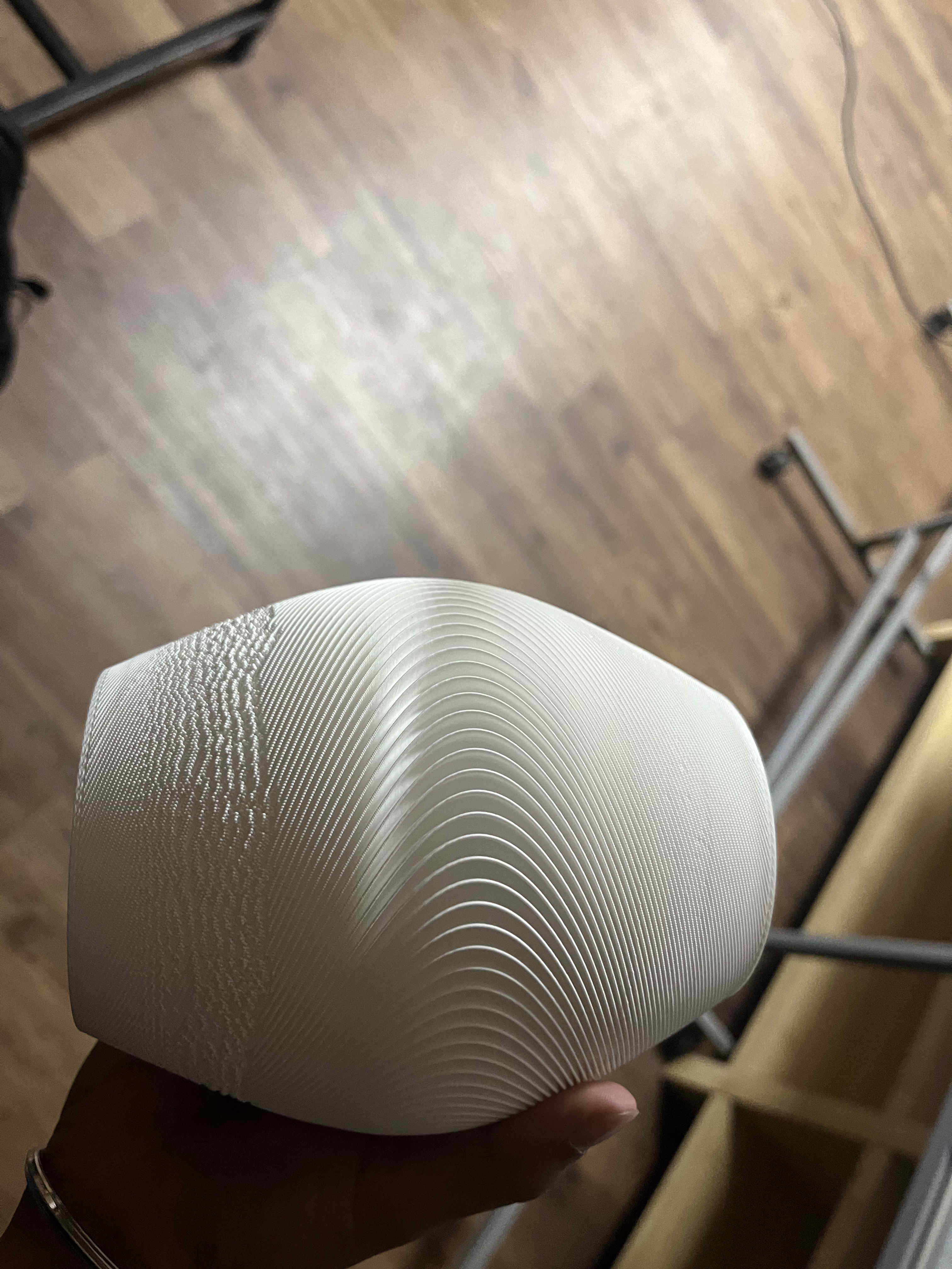
Final result
Final resultThe top half of the print faces some issue
i suspect its due t my ridge size(.5mm) be awfully close to my nozzle width(.4)
Soon we try non- planar again😈😈😈😈
𝄃𝄃𝄂𝄂𝄀𝄁𝄃𝄂𝄂𝄃.3D Scanning.𝄃𝄃𝄂𝄂𝄀𝄁𝄃𝄂𝄂𝄃
What is 3D scanning
3D scanning is the process of analyzing a real-world object or environment to collect 3D data regarding its shape, and texture.
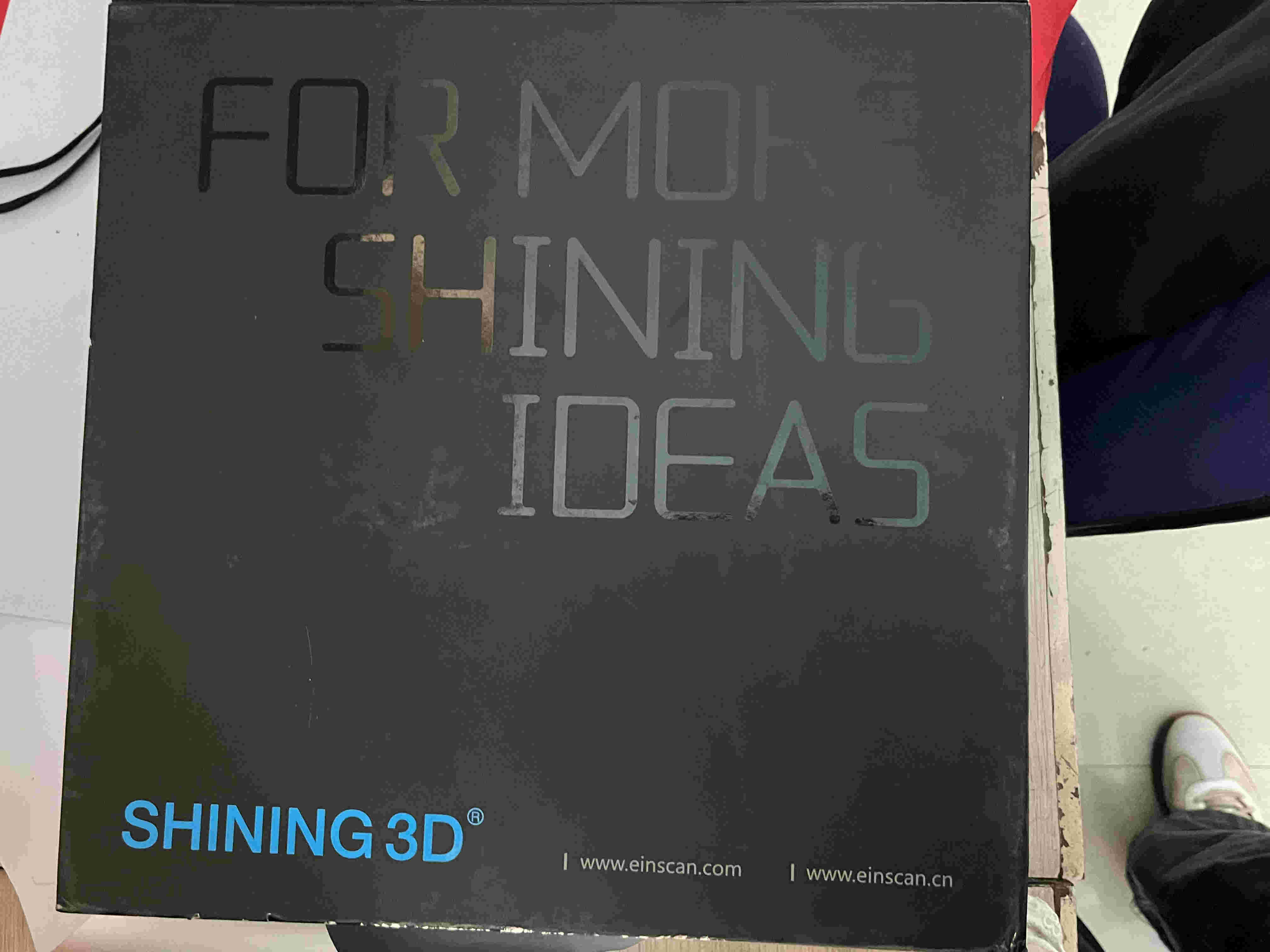
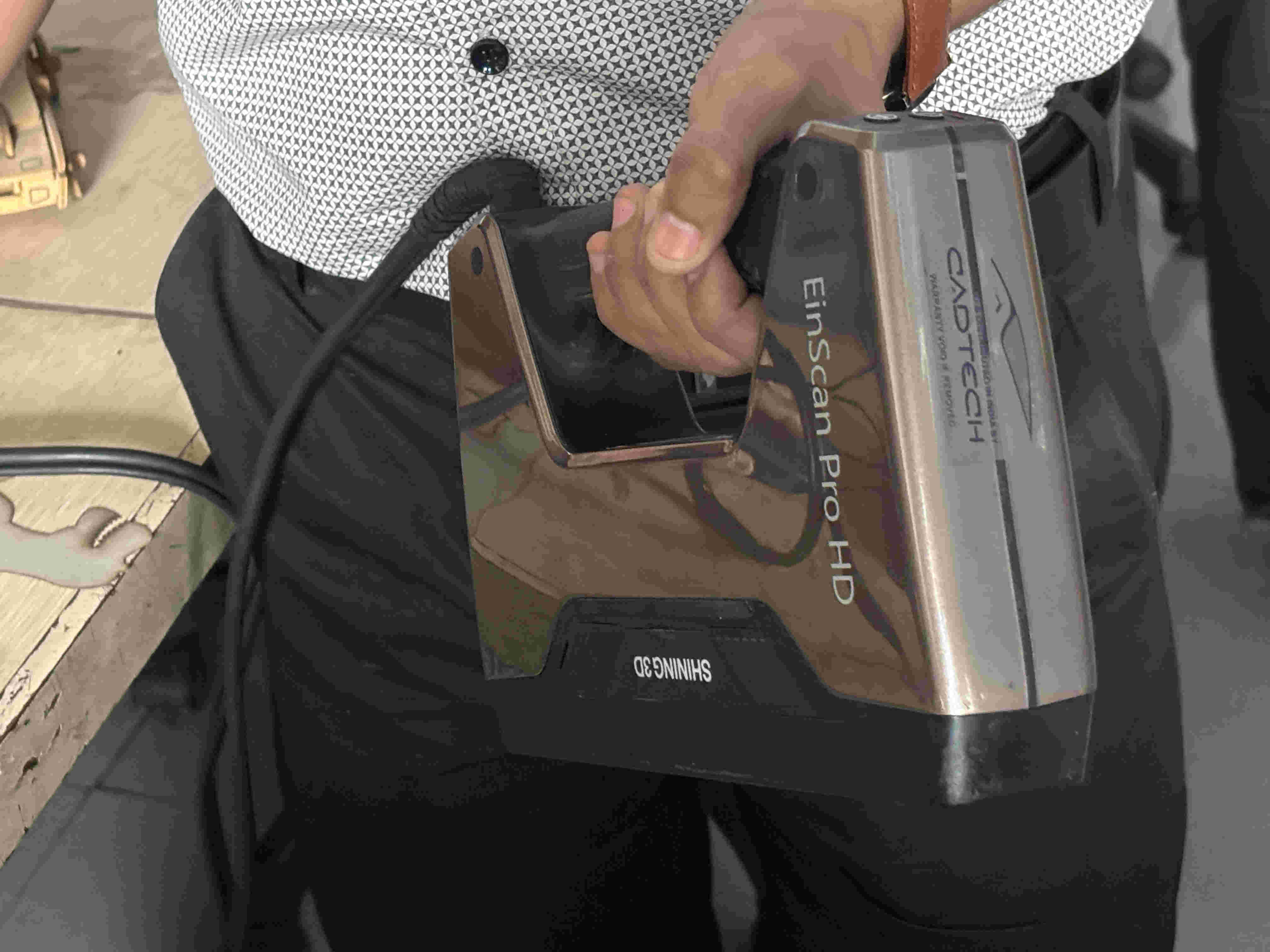
We were using the einscan 3D scanner for this week
It is a desktop/portable hybrid scanner that can scan using light as well as scanner dots.
The 3D gun with the einscan
The 3D gun with the einscan
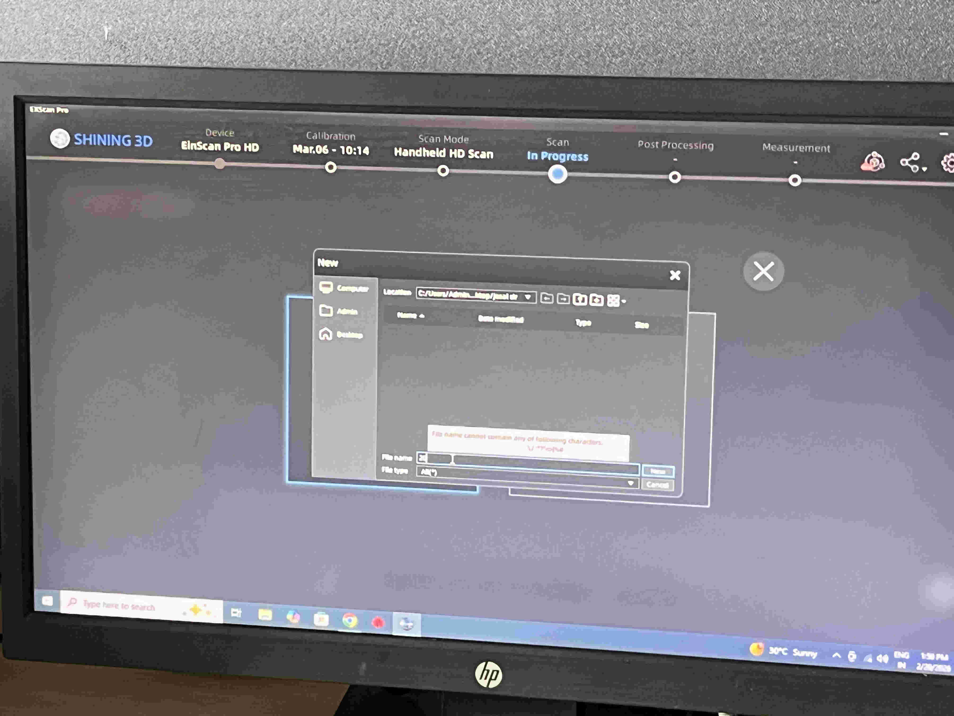
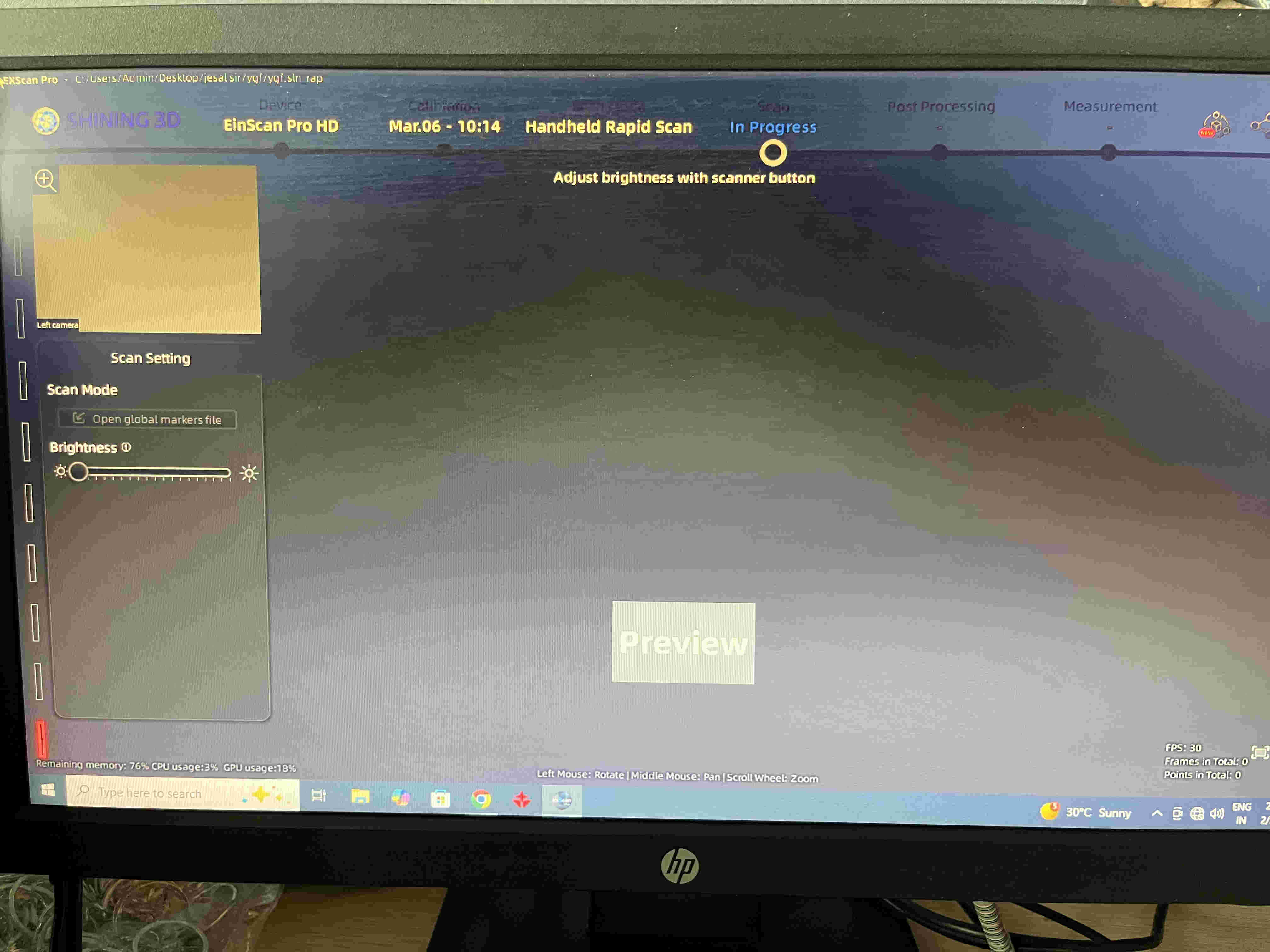
The software used is a proprietery software called Einscan pro
https://support.einscan.com/en/support/solutions/articles/60001048840-the-latest-software-for-einscan-pro-2x-v2-pro-hdFirst we name our file
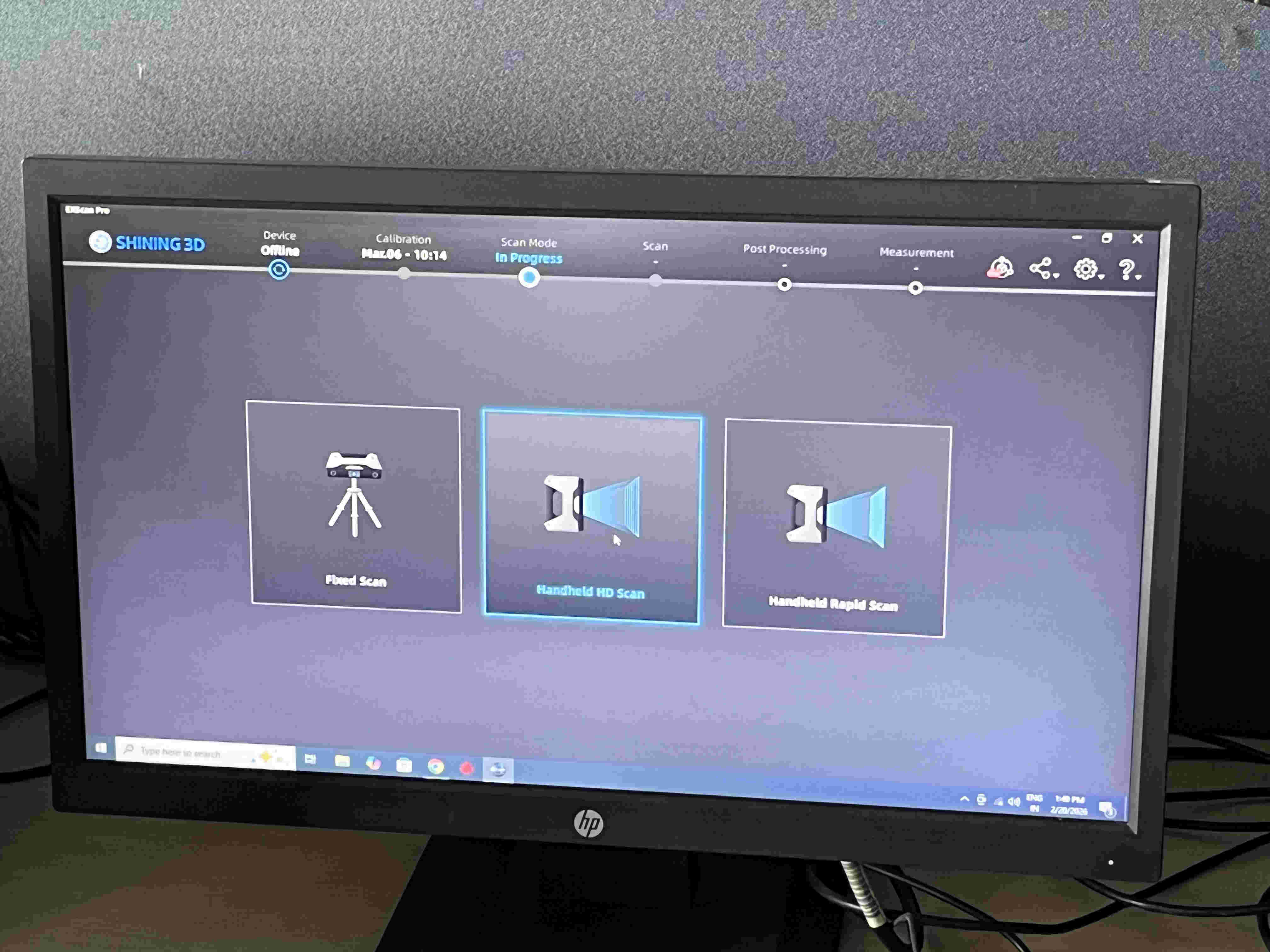
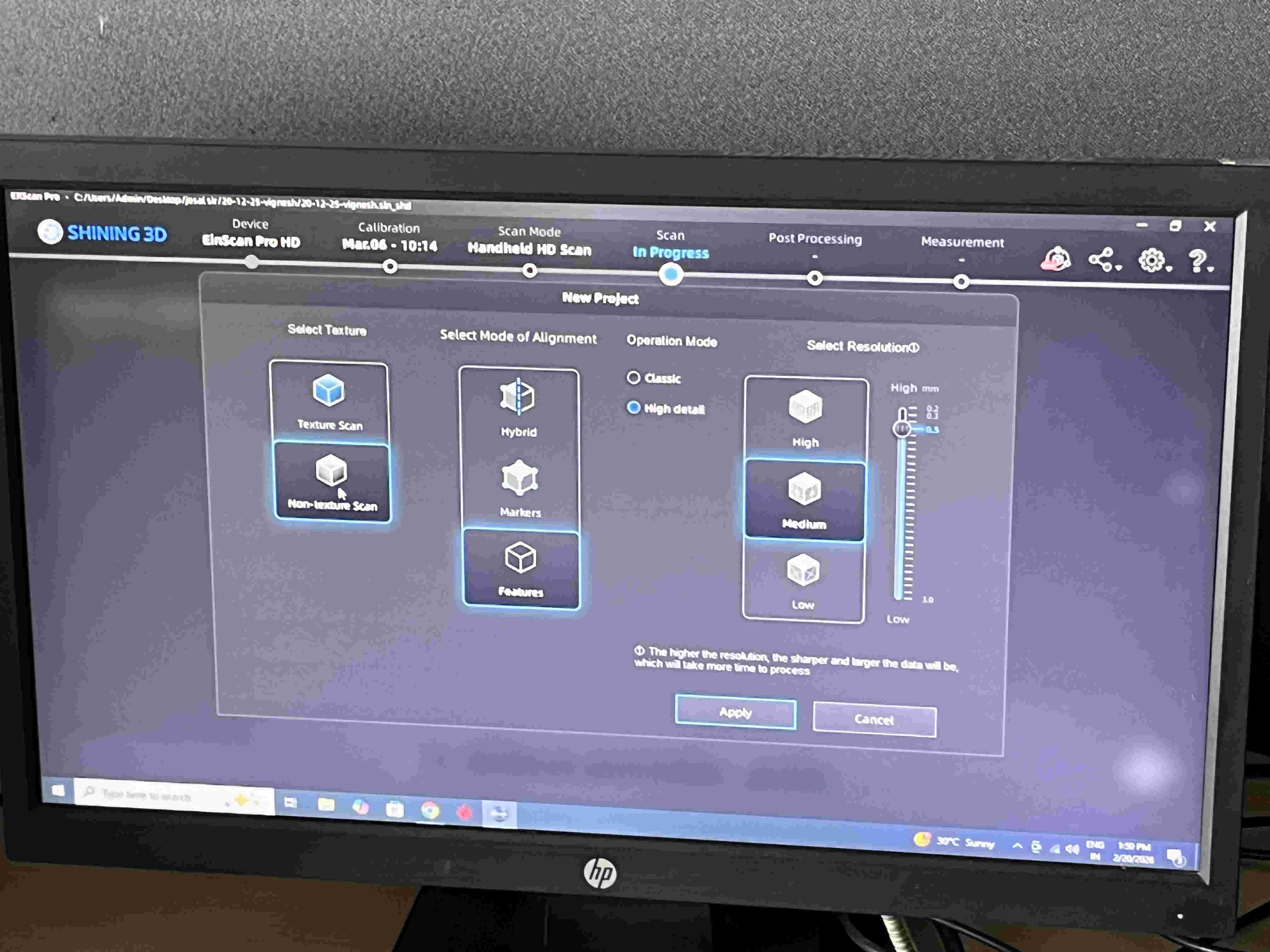
Second is mode selection.
Second is mode selection.
Different modes and how they work.
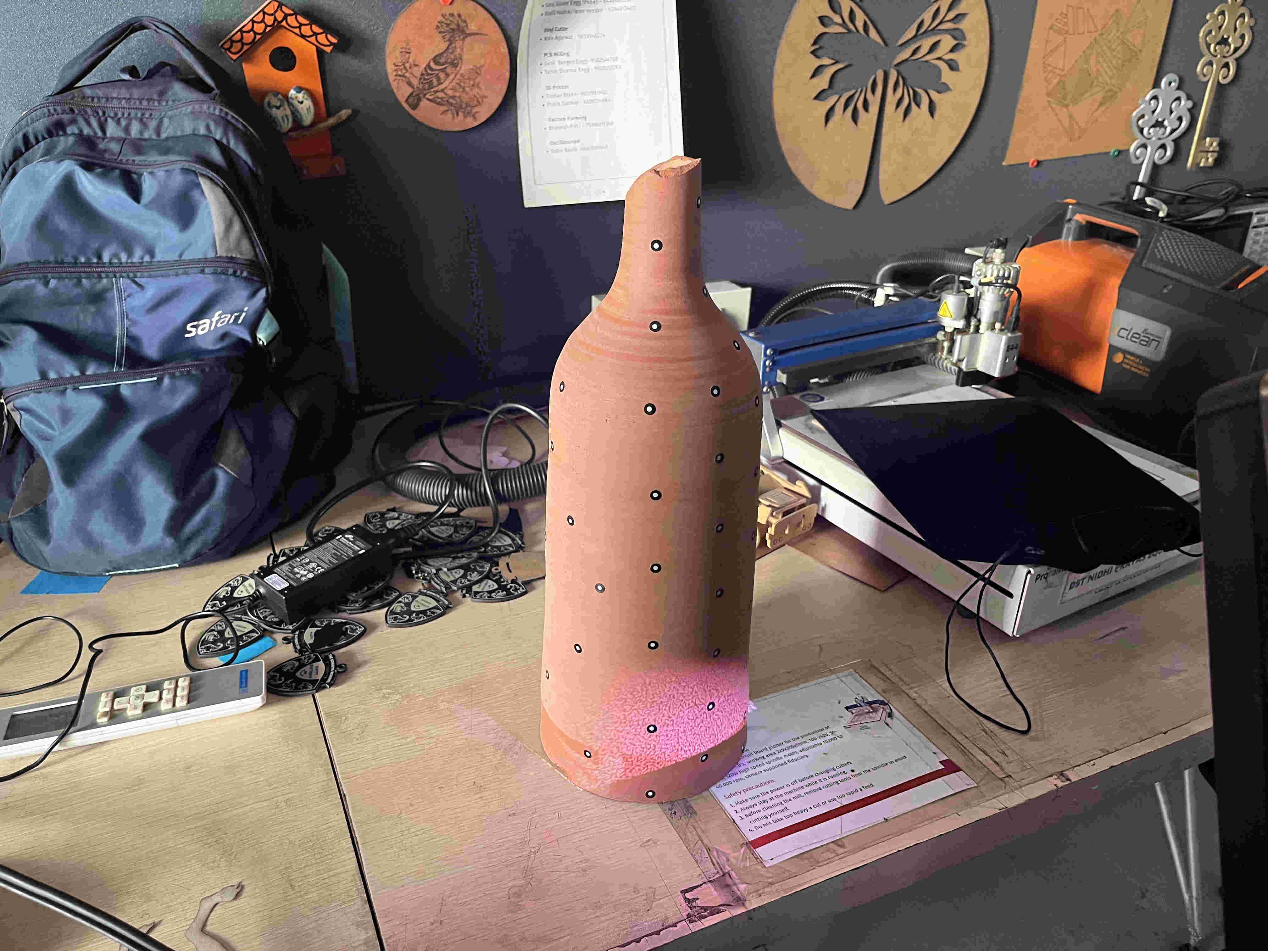
For starters we tried a pottery vase, lined it with dots and started scanning.
Unfortunately because of some techincial issue, the Einscan wasnt feeding anything to the pc, even the preview window on the top left of the software was blank.
Temporarily working with Kiri Engine - Li-dar Scanning
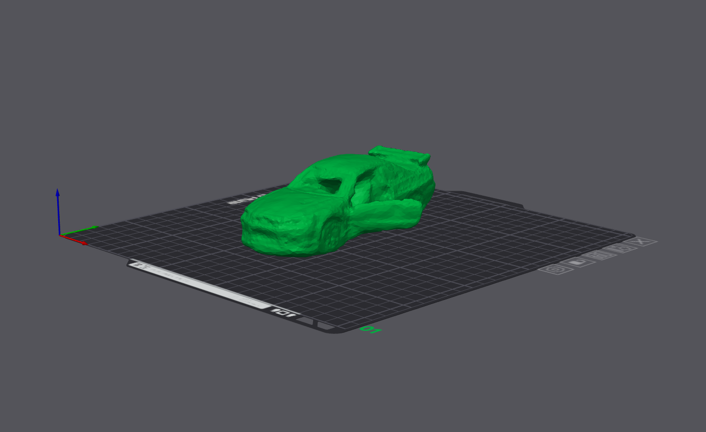
Kiri engine is a photo based 3d scanner(on most phones). that enables a smartohone with a camera to be a 3d scanner
The model is oriented in a space and multiple photos are taken from different angles and elevations, that acts as dataset for the software to create a 3d model.
ALSO
Phones that support lidar, (all Iphone pro models), can use the same technology as the einscan to generate a 3d model right on yoou phone.
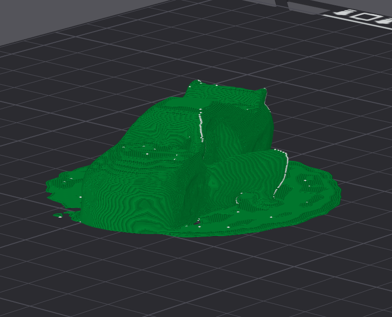
Photoscan resultLi-dar scan resultSome of the files in this weeks exploration are veryyyy heavy, thus I have added those files on drive and sharing a link here.https://drive.google.com/drive/folders/10e3MTSSuun_q6KfYZeDMSMj6cKZn07kZ?usp=share_link
Link to heavy files that i cant post here
since kiri engine requires paid export, I wasnt able to atatch the files 3d model files here.