Exploring different laser cutters and vinyl cutters was all about this week
.Group work.
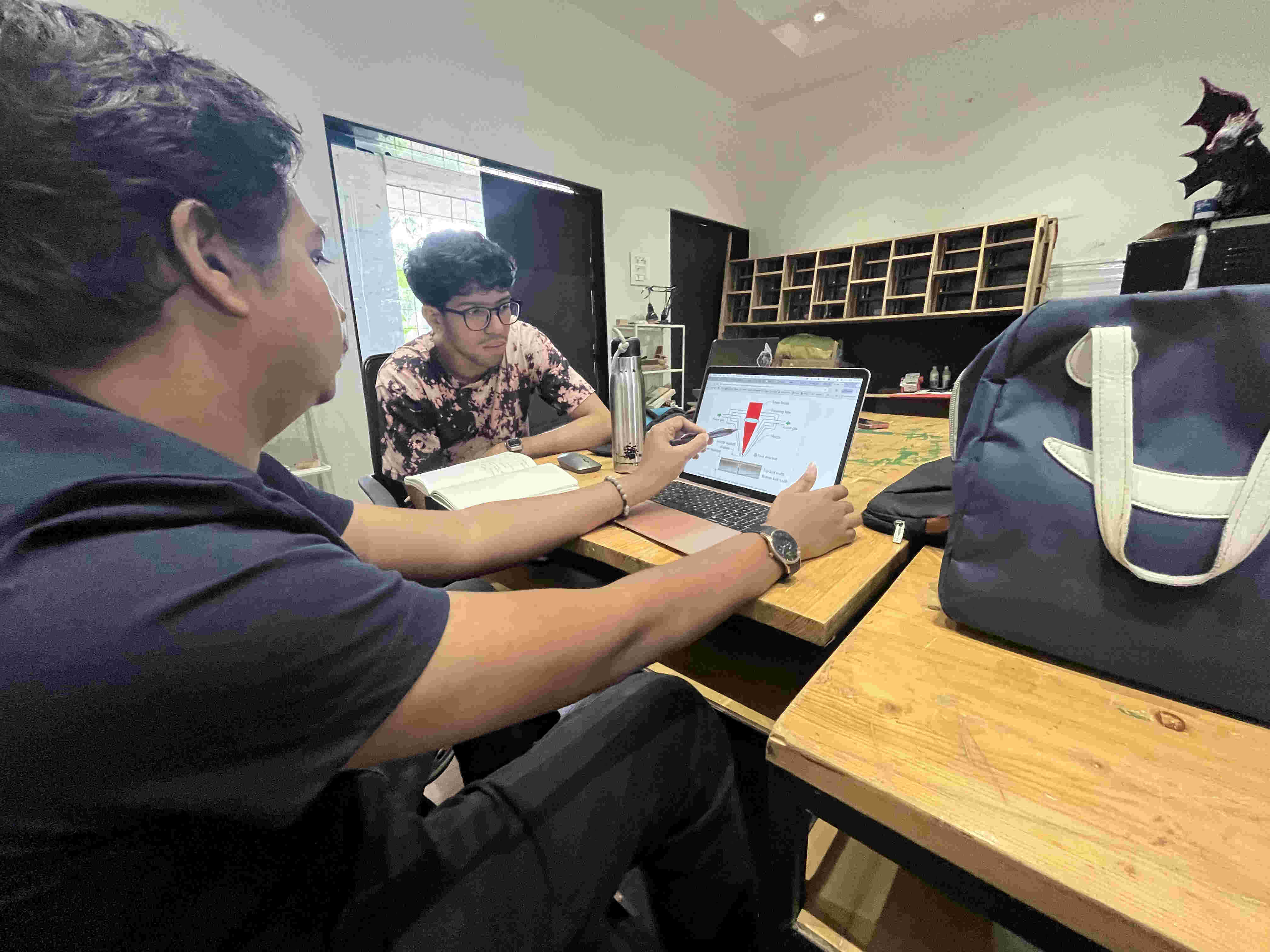
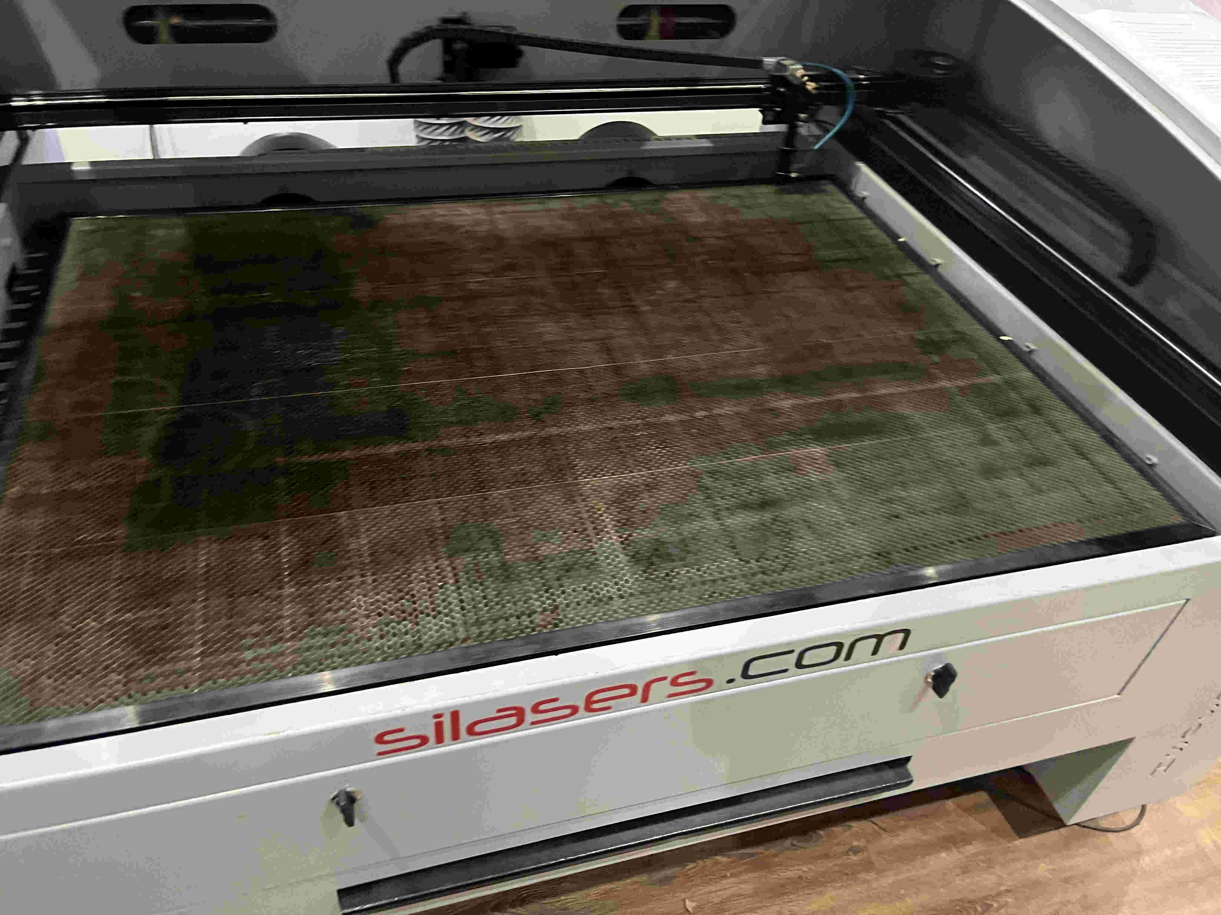
We started by understanding the laser machine
First step was undertsanding all factors that have a pin point precision while cutting on a laser cutter,
we exlored focus, kerf, rate, speed power and more.
what is focus?
On a laser cutter the beam of a laser is focused at a point using a concave lens, finiding this point is crucial as without it the lasered lines will be too thick and innacurate
What is kerf focus and why is it crucial.
Kerf
Kerf is the width of material removed by the laser beam as it cuts. Think of it like a saw blade's width — the laser doesn't cut a perfectly zero-width line; it vaporizes a narrow strip of material. Typical CO₂ kerf is 0.1–0.5 mm depending on material and settings. You need to account for kerf when designing precise parts (e.g., press-fit joints need to be slightly oversized in the design to compensate).
Speed
Speed is how fast the laser head moves across the material, usually in mm/s or mm/min. It directly controls how long the laser dwells on any given spot:
Slower speed — more energy delivered → deeper cut, more burn, wider kerf
Faster speed — less energy → shallower cut, cleaner edge, less char
Speed is always tuned relative to power — neither setting works in isolation.
Power
Power is the percentage of the laser tube's maximum output being used (e.g., 0–100%, or sometimes in watts). It controls the raw energy of the beam:
Higher power — cuts thicker materials, engraves deeper
Lower power — suitable for engraving, thin materials, or delicate scoring
On most machines, there's a min/max power setting — min power kicks in when the head decelerates at corners, preventing burn spots.
Focus
Focus refers to the vertical position of the focal point of the laser beam relative to the material surface. The beam is cone-shaped, and it's thinnest (most intense) at the focal point:
Correct focus — smallest spot size → cleanest, narrowest cut with maximum power density
Too high/low — larger spot → wider, fuzzier kerf, less cutting power, rougher edges
Focus is set by adjusting the Z-axis (bed height) so the focal point lands at or slightly below the material surface. For cutting, focus is usually set at the material surface or just below. For engraving, focus at the surface gives the finest detail.
How They Interact
Goal
Speed
Power
Focus
Cut thick material
Slow
High
At/below surface
Cut thin material
Fast
Medium
At surface
Fine engraving
Fast
Low
At surface
Deep engraving
Slow
Medium–High
At surface
The sweet spot is always a balance — too much power or too little speed causes charring, warping, or fire risk; too little power or too much speed results in incomplete cuts.
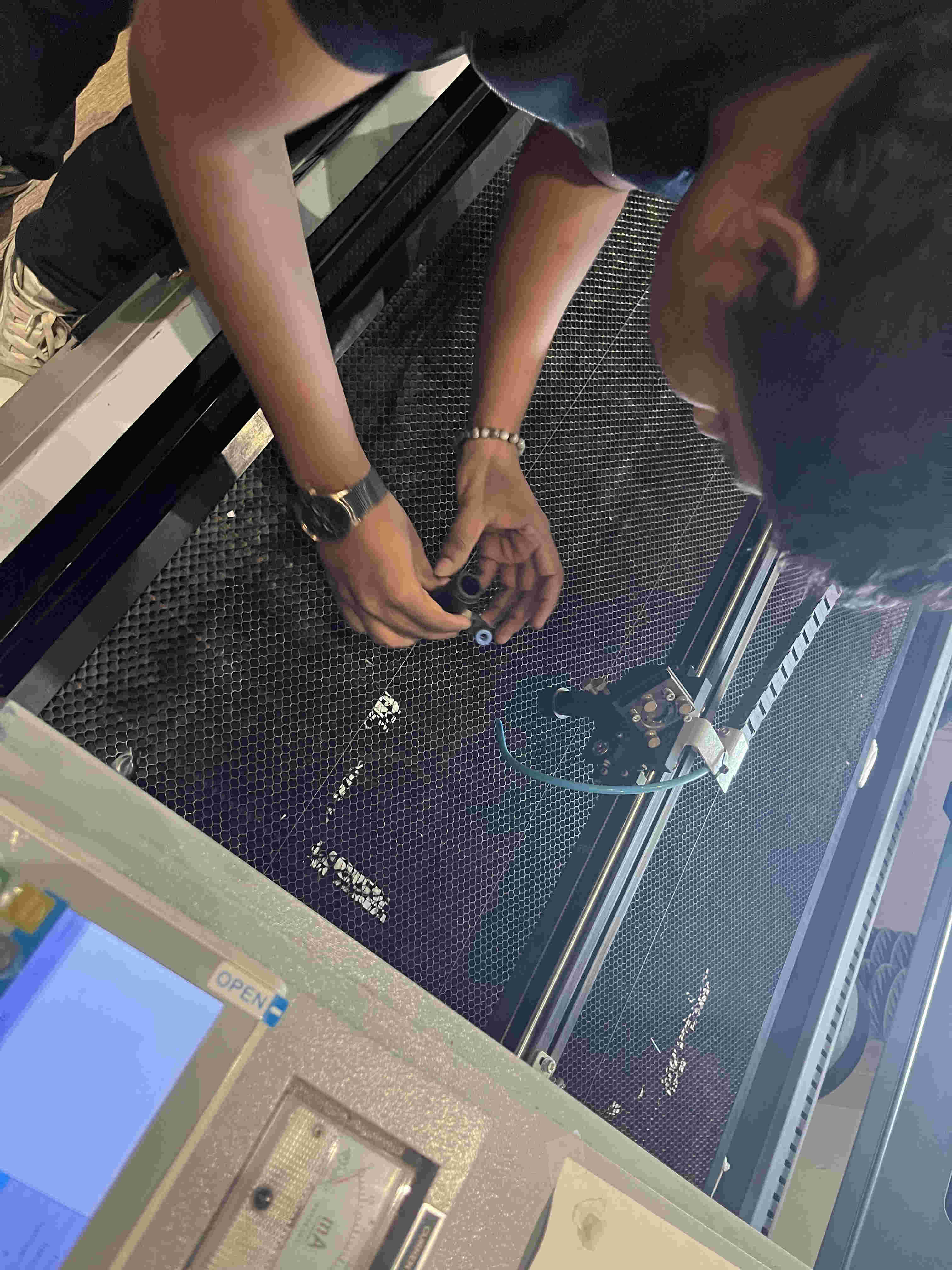
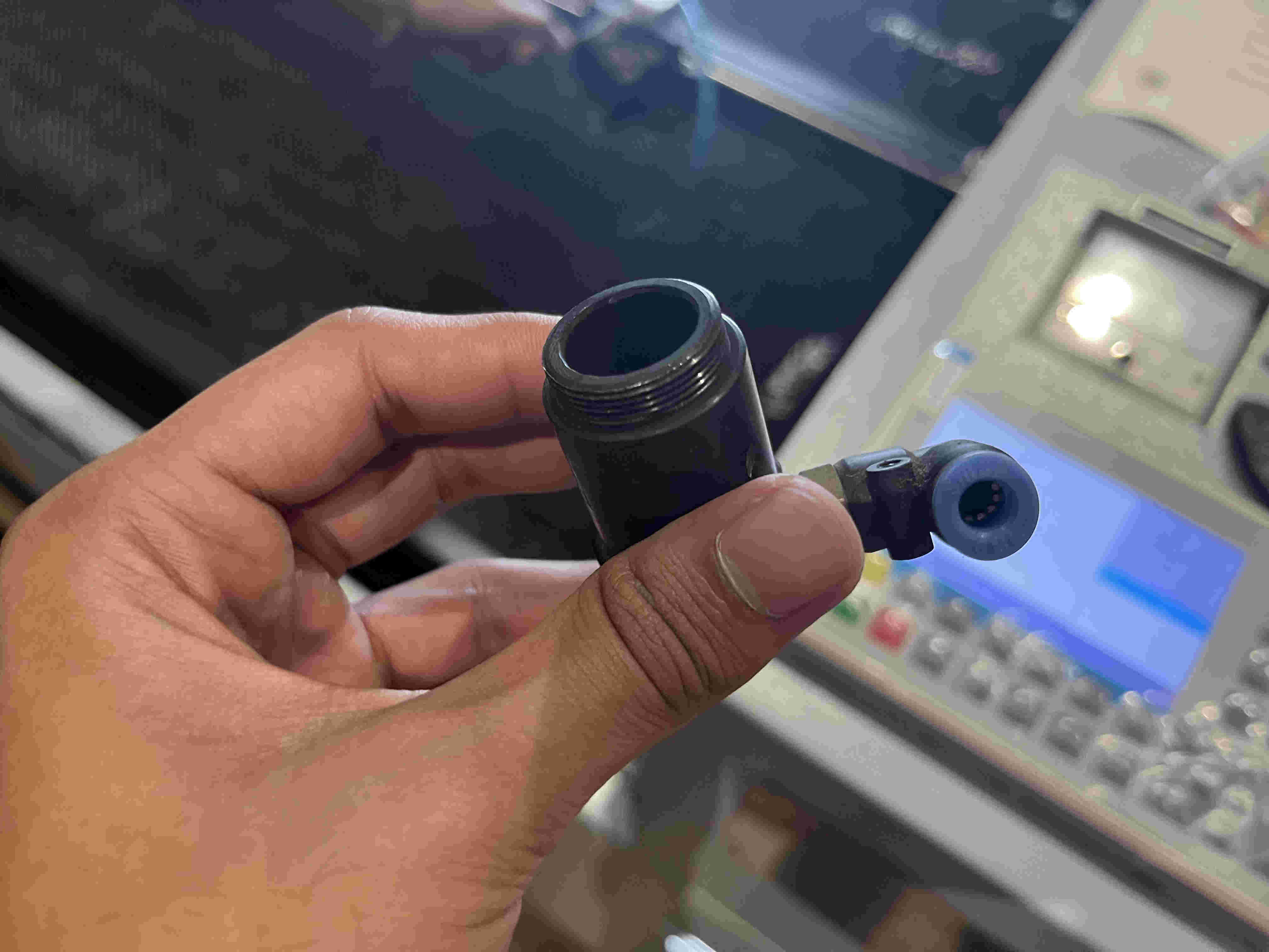
Looking at the various lenses involved
Nozzle and air blower nozzle.
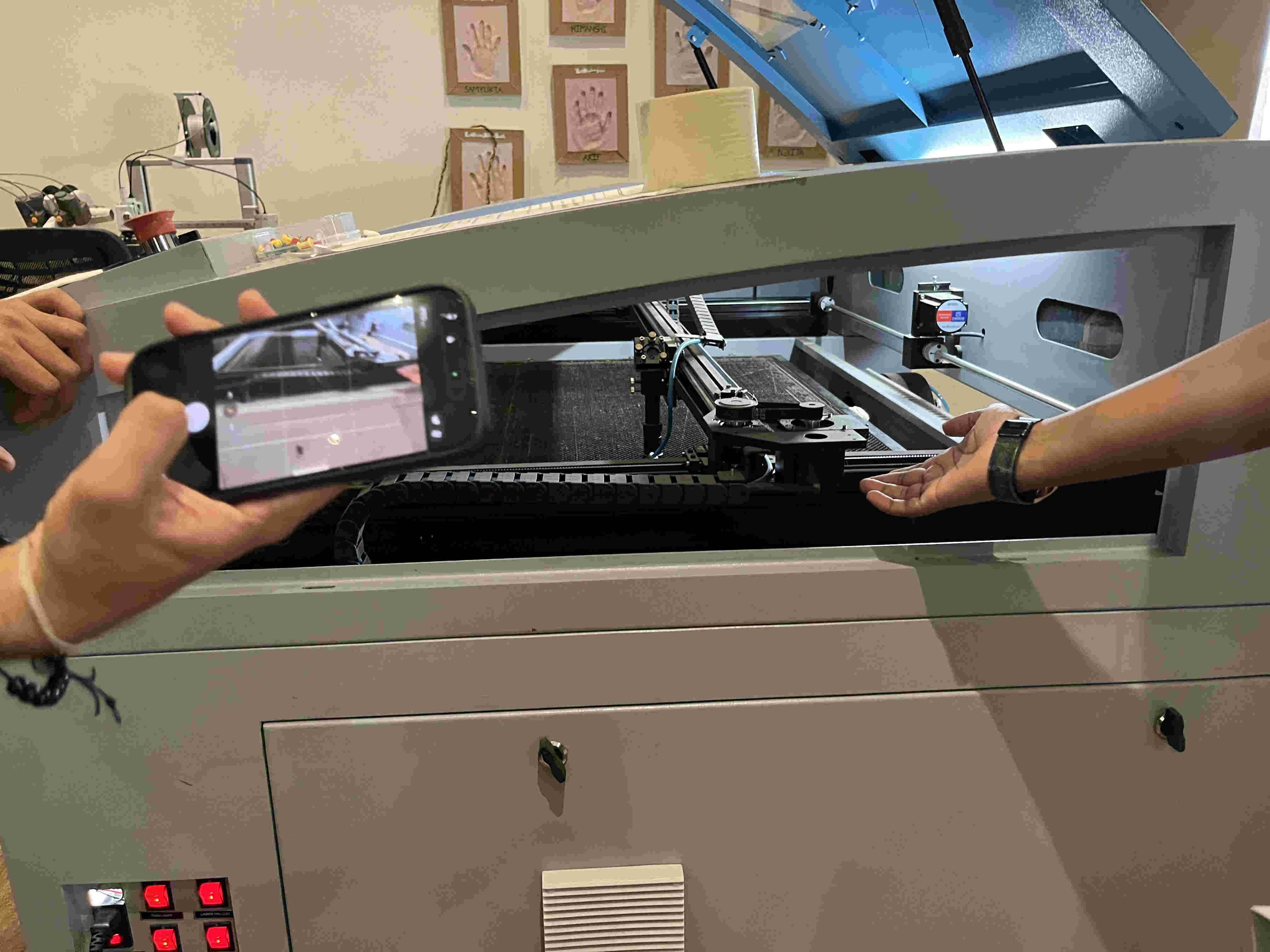
Mechanisms and rails involved in the X/Y/Z motion of the nozzle.
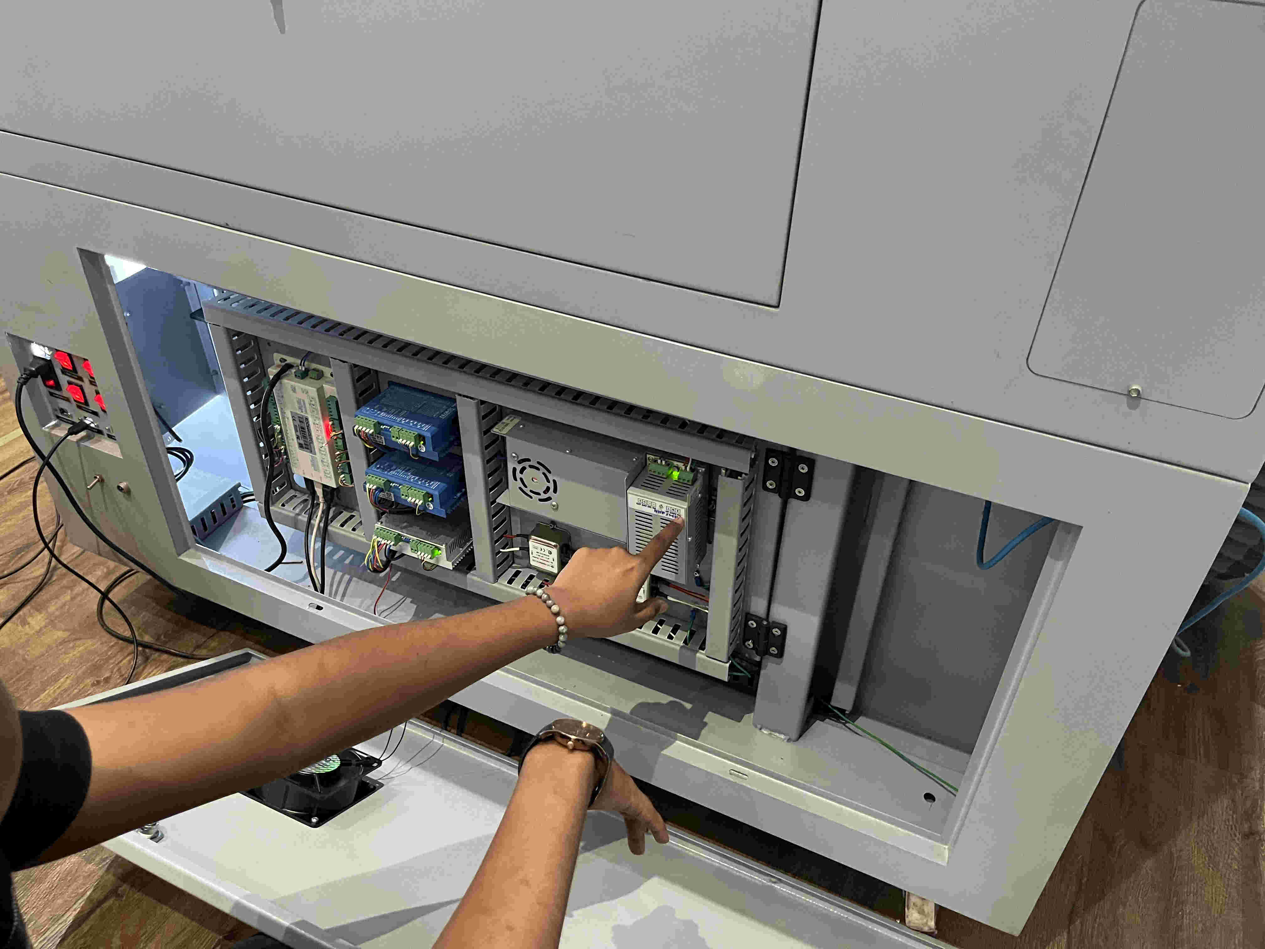
Small run through about the electronic components
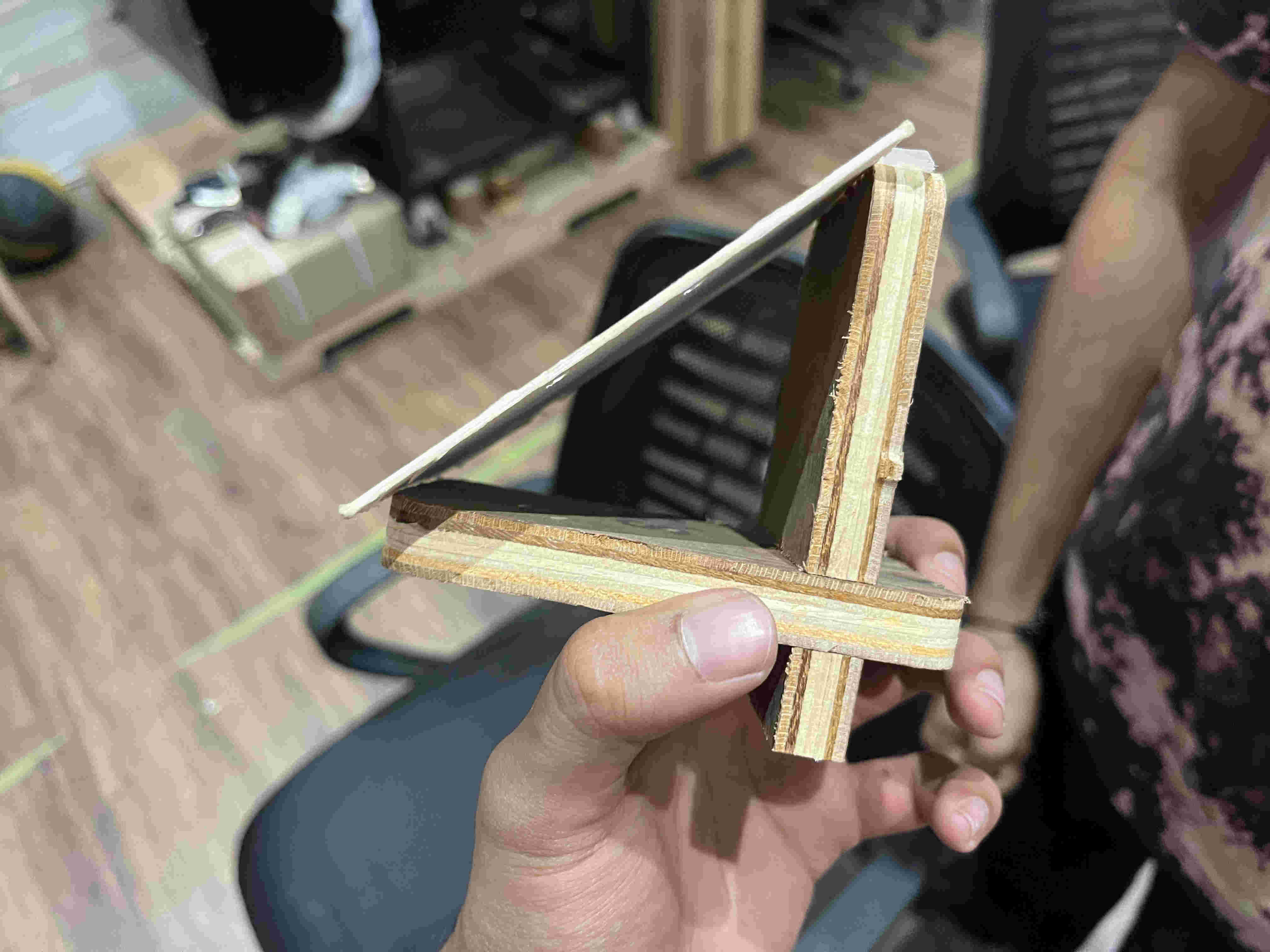
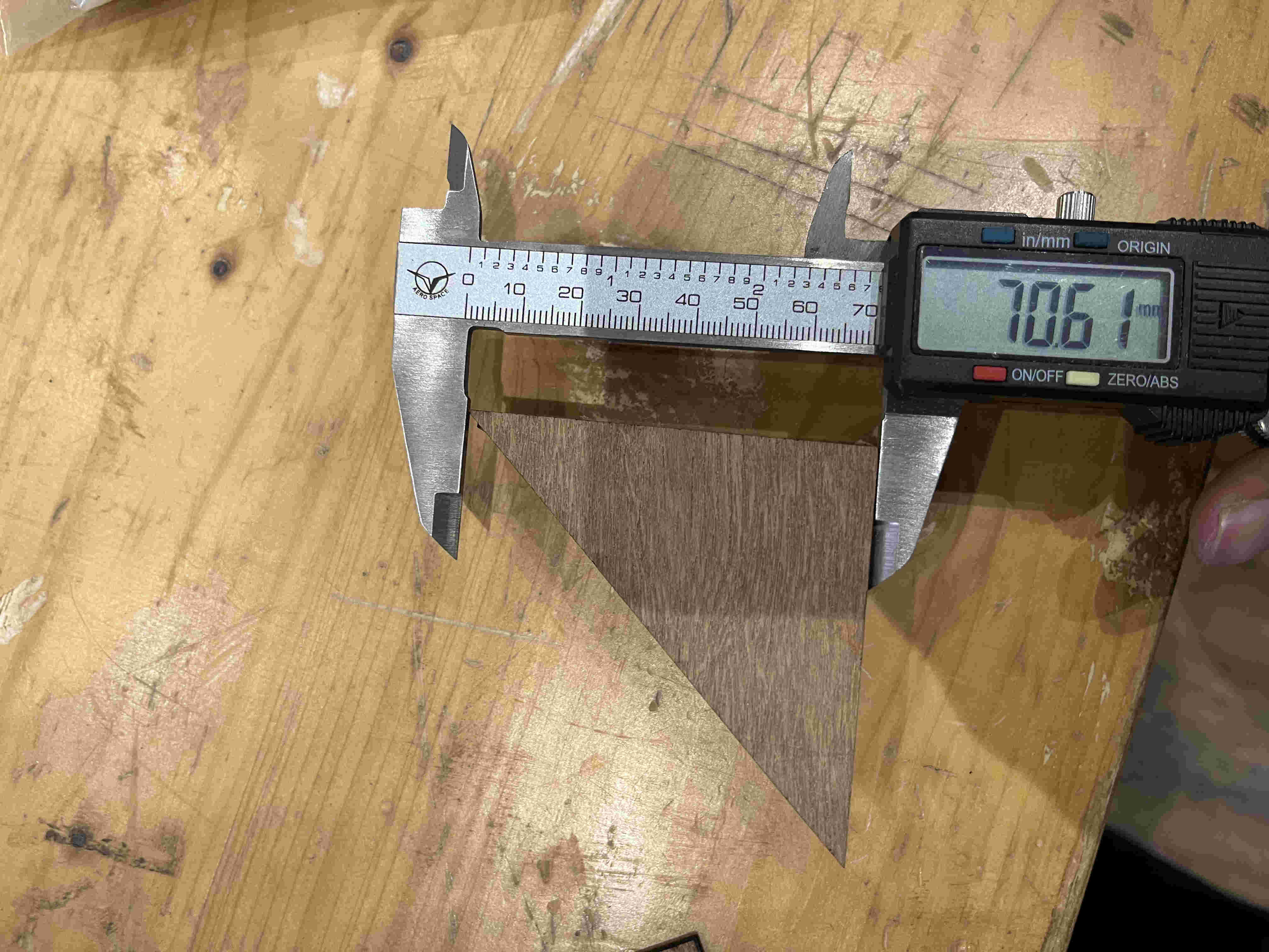
To find out Focus- we employed a method of using a 90 degree triangle, and making various lines .5mm apart from left to right.
How this works is that one of the lines out of the multiple lines will be the sharpest. by calulating the hypotenuse of that point to the highest point of the triangle we can accurately calculate (upto.5 mm) the focus point of the laser
The wooden right angle wasnt very accurate so we used a plywood right angle jig to create it.
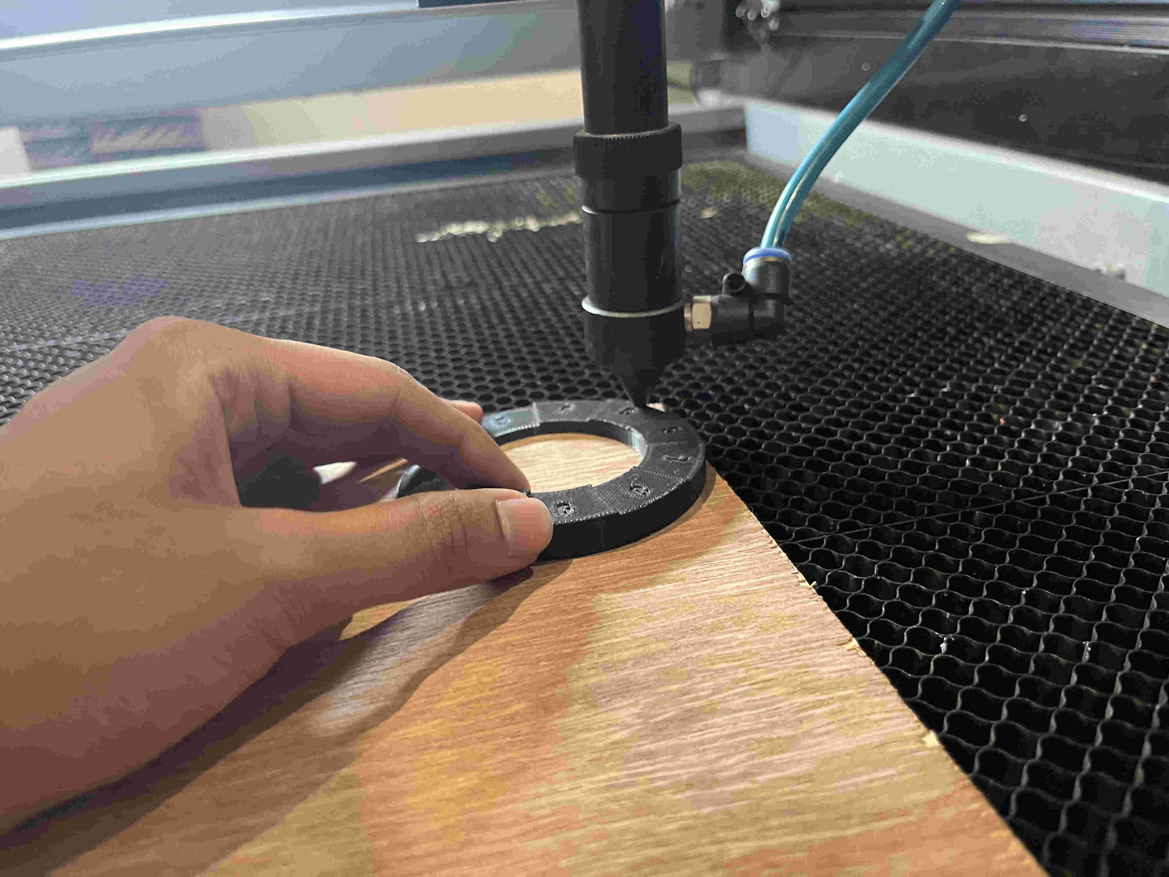
For the sake of cutting ply now, we use a spacer tool to leave a gap of 3 mm(this is not the accurate focus point).
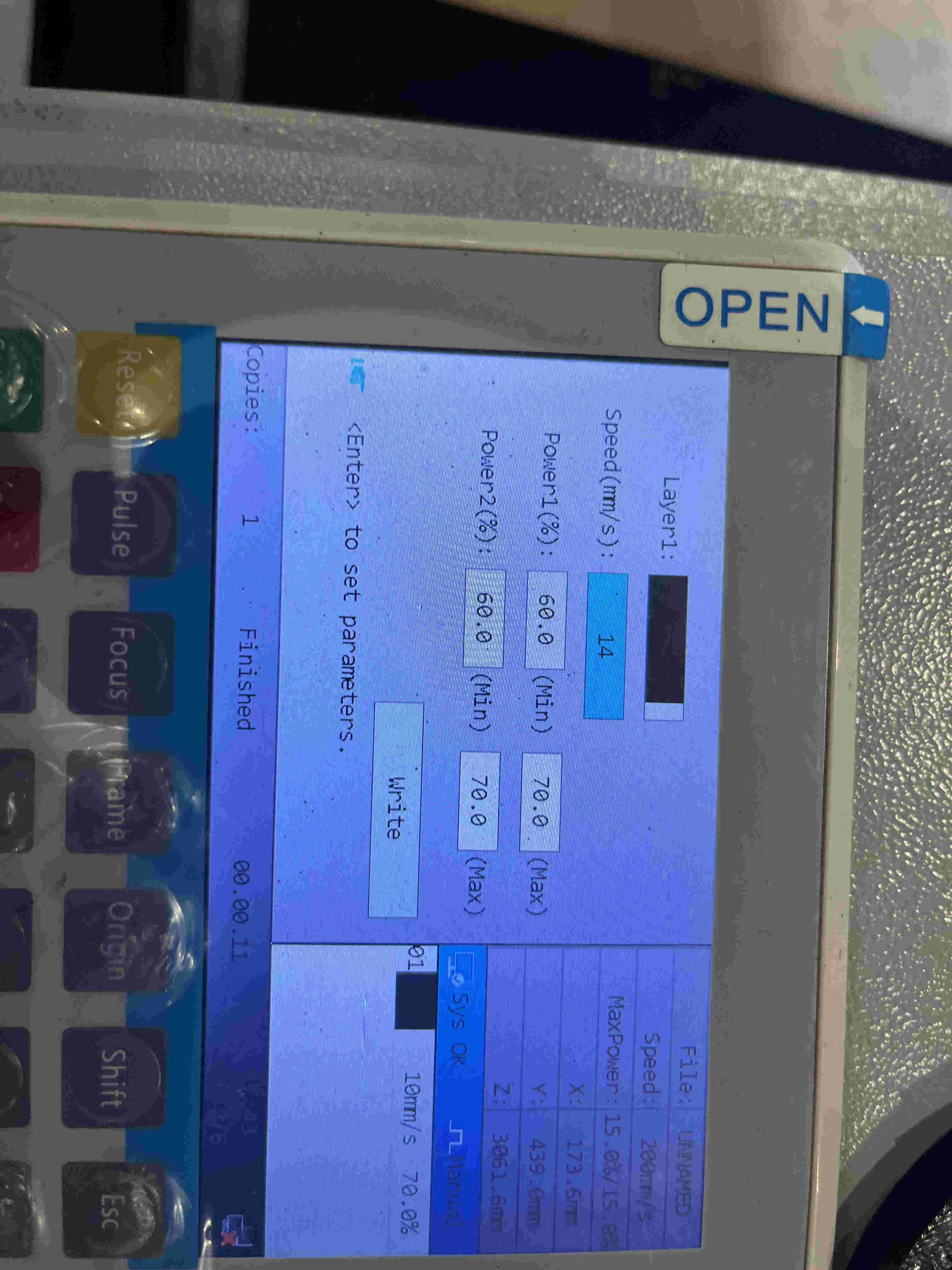
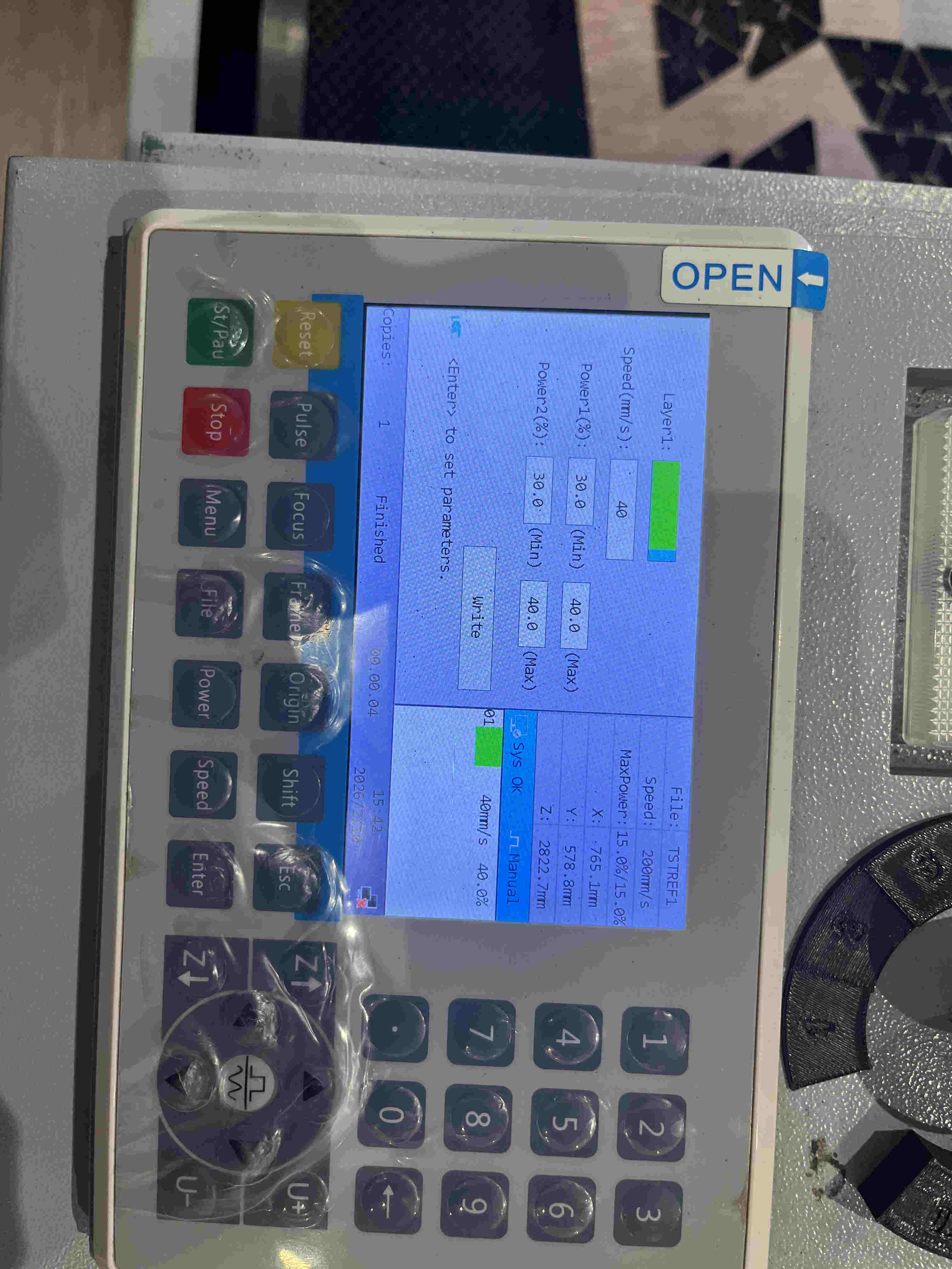
Experimenting various speed power settings for optimal cut.
speed- 40
power min-30 max-40
material - 3mm plywood
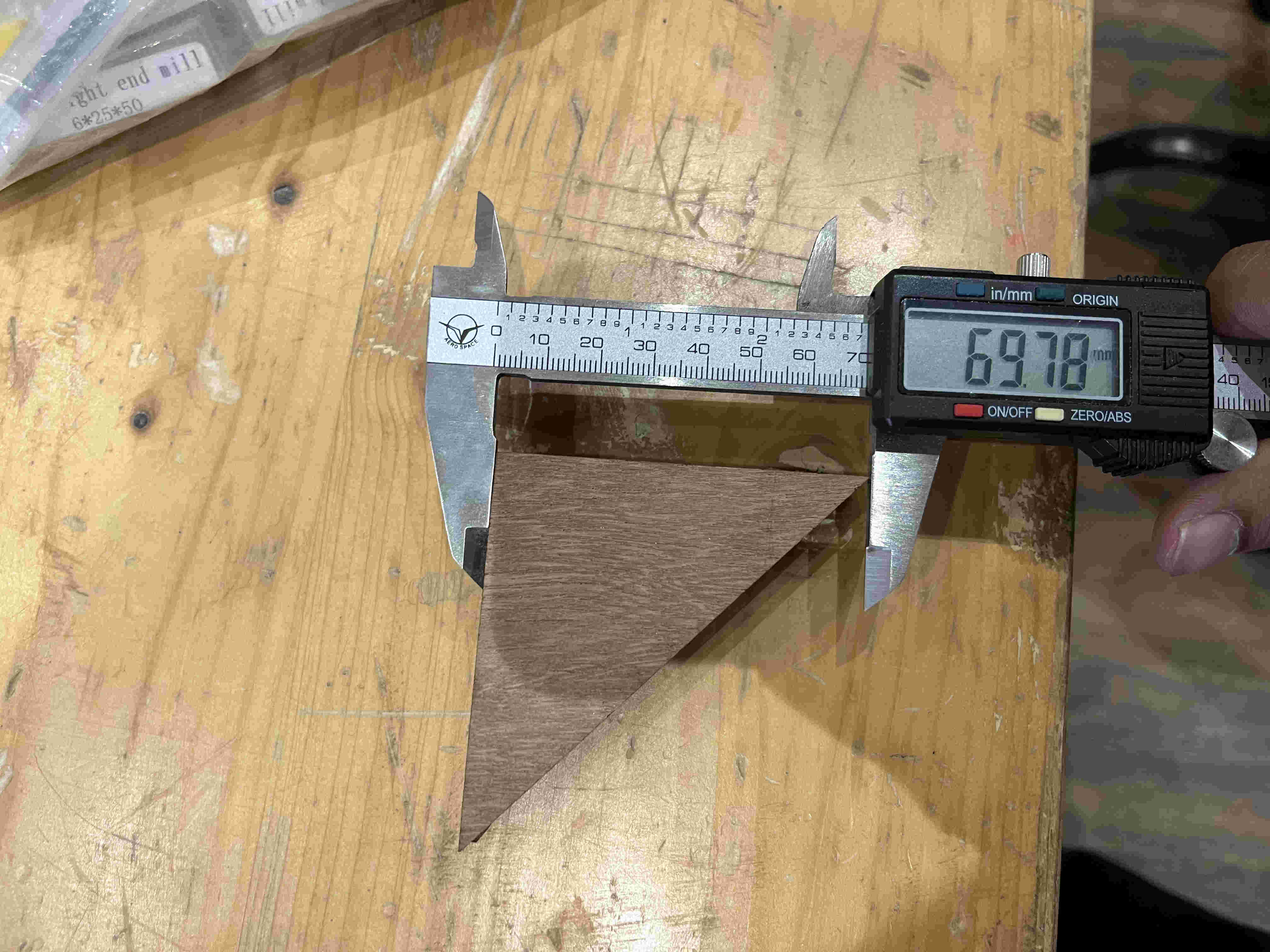
We mad the mistake of making unequal lengths of the two sides of the right angle triangle
for a proper 45 degree angle at both ends, IT IS IMPORTANT for the triangle to be a isoceles right angle triangle.
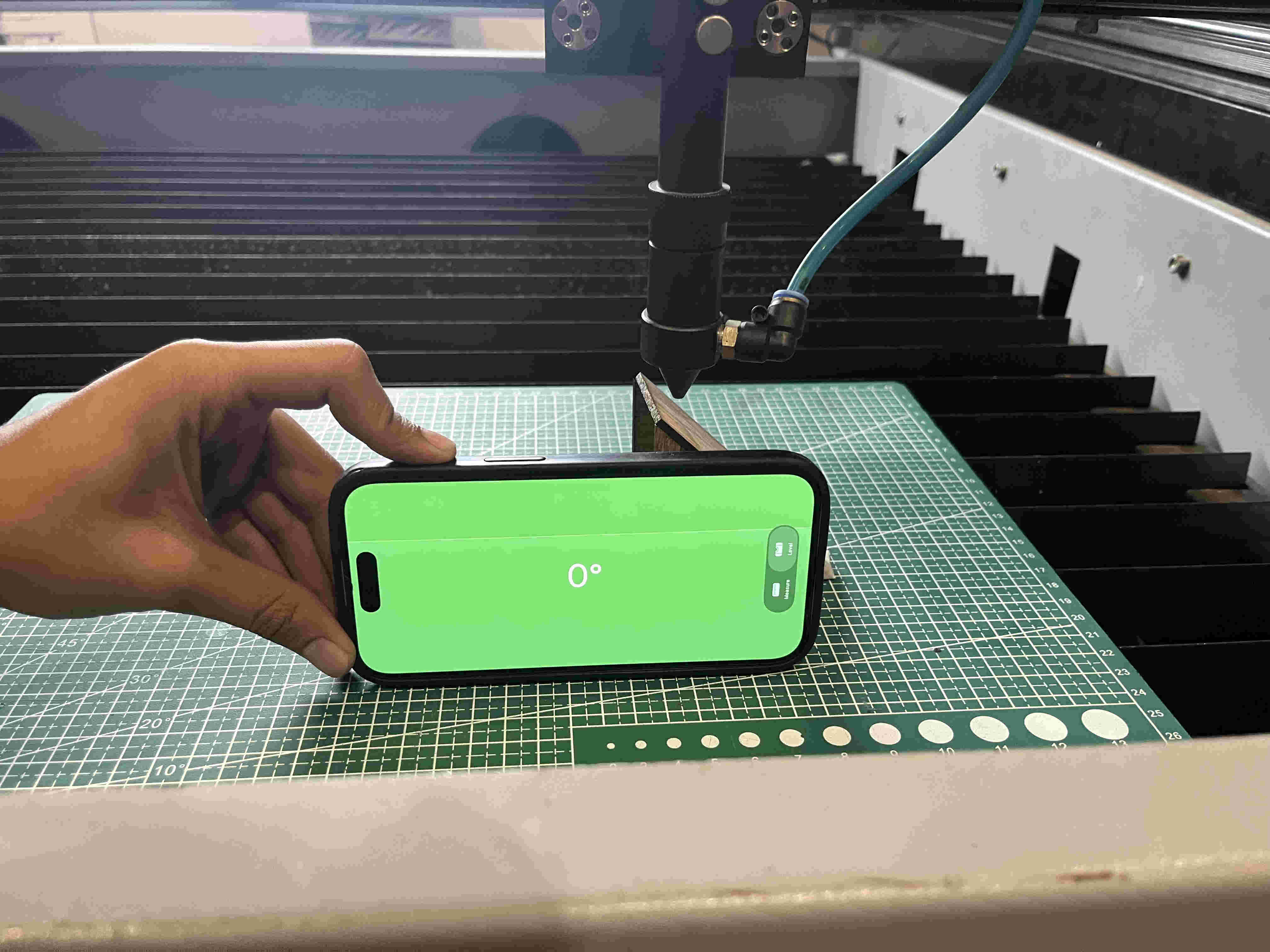
Once we had the jig ready we realised that it was too high, such that the nozzle hit the triangle piece so we removed the bed and placed a cutting mat below and made sure it is level to avoid innacuracy
Result 1- the top most line was clear but it could get clearer.
The triangle was still to high so the nozzle coud not clear it past the last line
The laser itself has a certain thickness. so if you cut 20 mm square, the dimesions will be off and smaller by the thickness of the laser
Finding and accounting for this in your design enhances accuracy of dimensions down to the decimals.
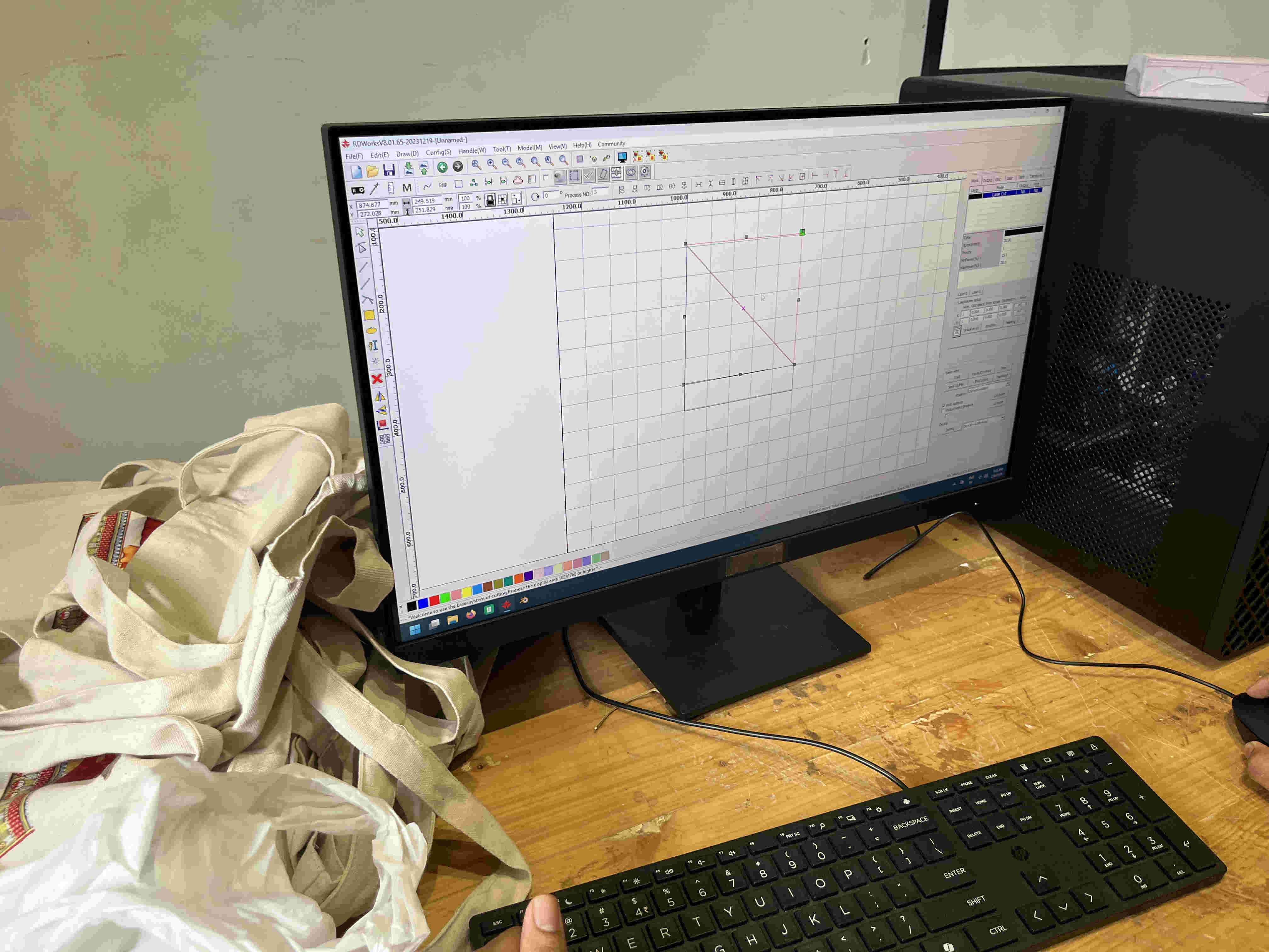
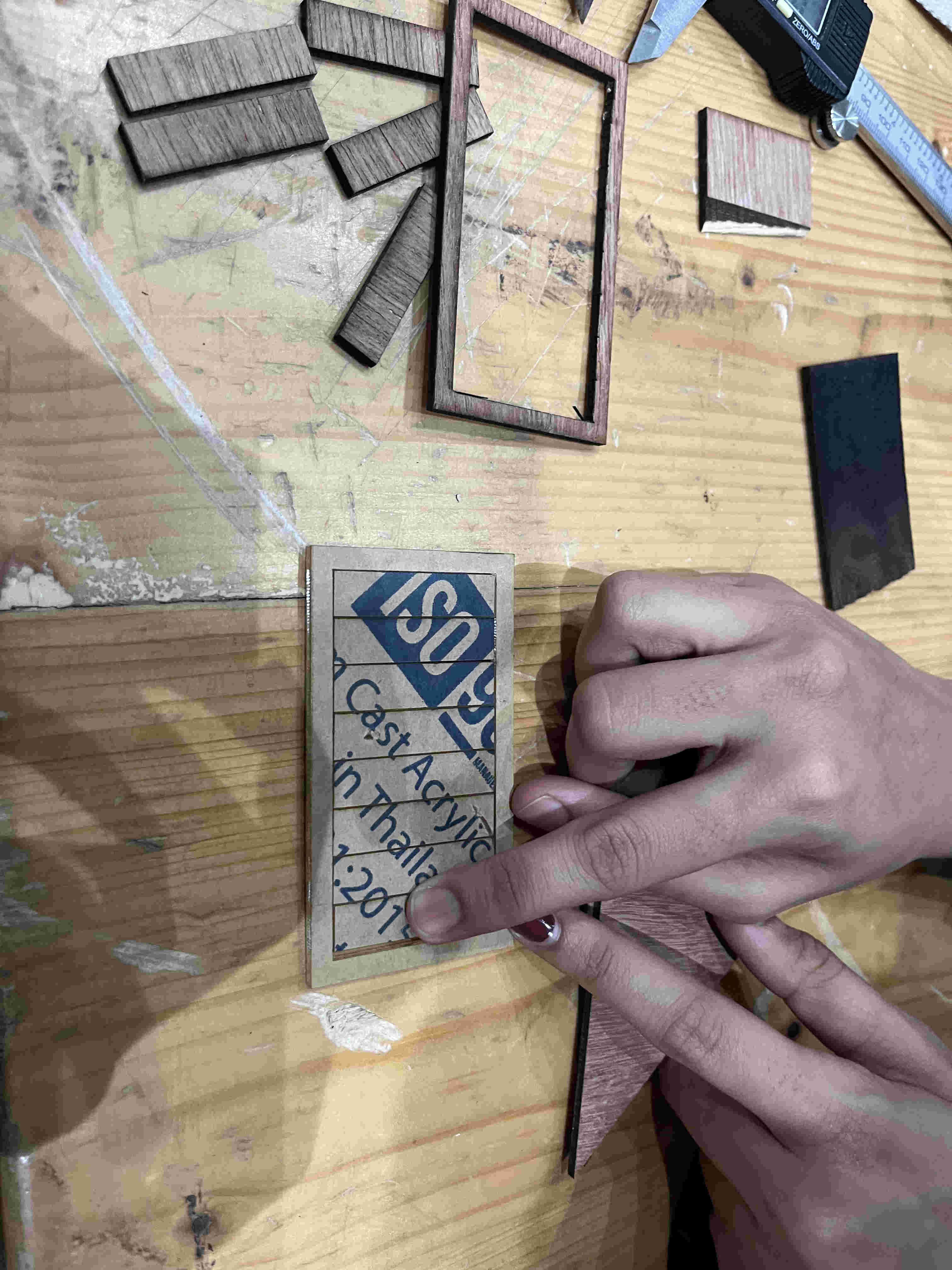
For this we used the comb test
How this works
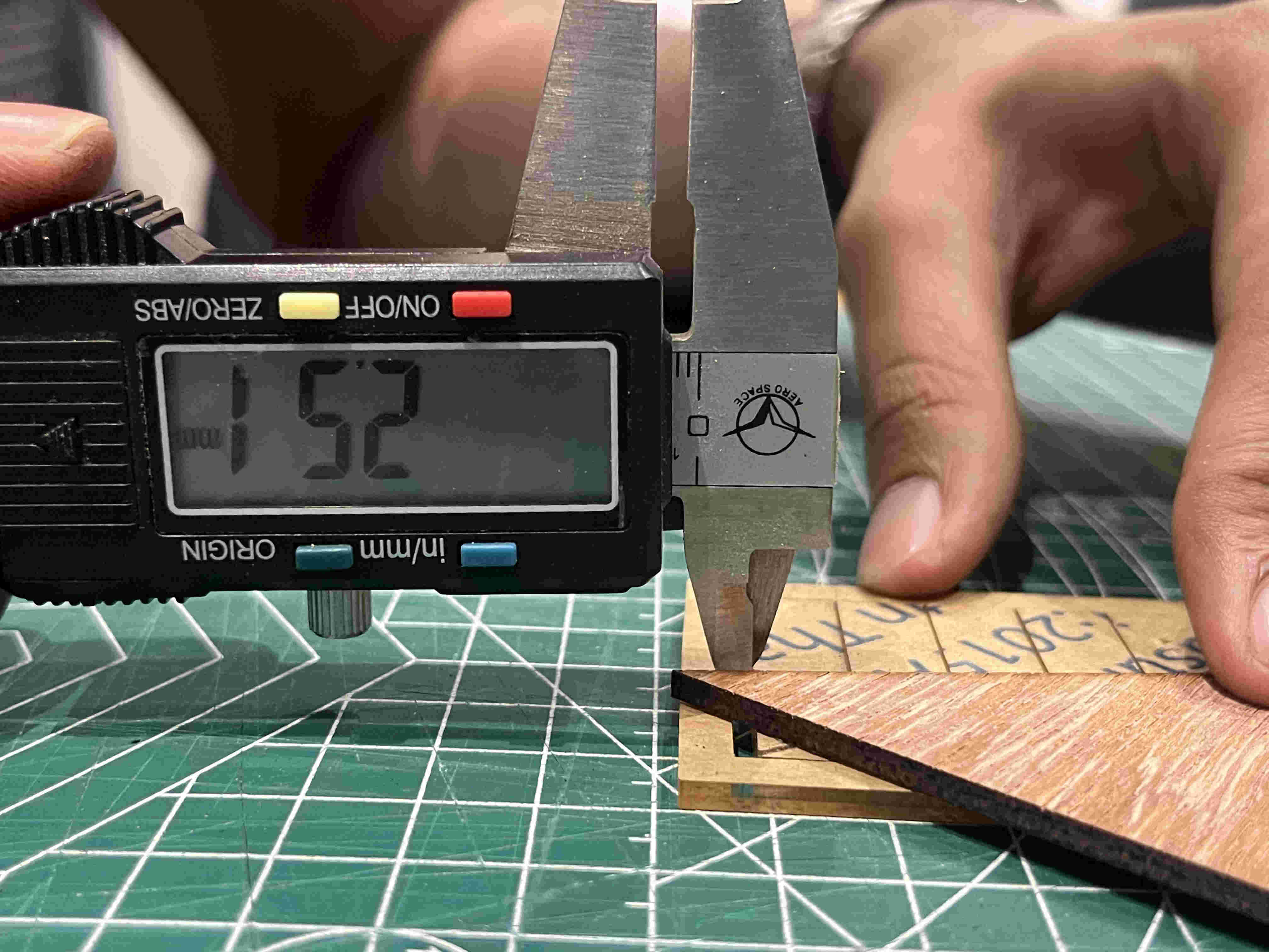
We create a rectangle with multiple line all to be cut, once cut the centre rectangular strips that come out can all be pushed to one side. which will give us the total innacuracy due to kerf. divide that value by the number of lines and you get your kerf
All centre pieces pushed to one side
Value coming upto- 2.52
2.52/8 (number of lines) = .315
Cleaning our beds and turning off machines at the end of the day.
.Individual Assignment.
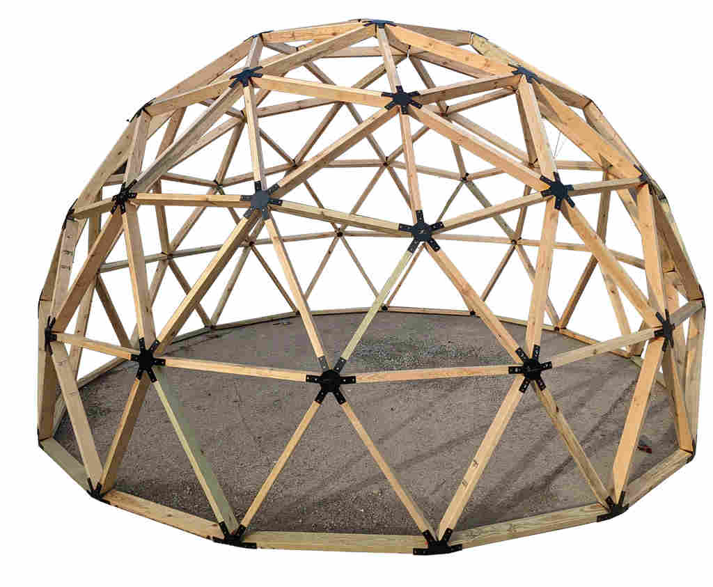
My concept- My first inspiration, or rather a kick off point after the lectures this week was the geodeisic dome.
I wanted to create a construction kit using slotted basic forms that can make a dome or something close to it.
Along with a dome structure i was imagining a a fractal caustics lamp that i could keep on tabletops
I hoped on chatGPT to disscuss what could be the best shape to create a fractal dome and have varitaion for caustics.
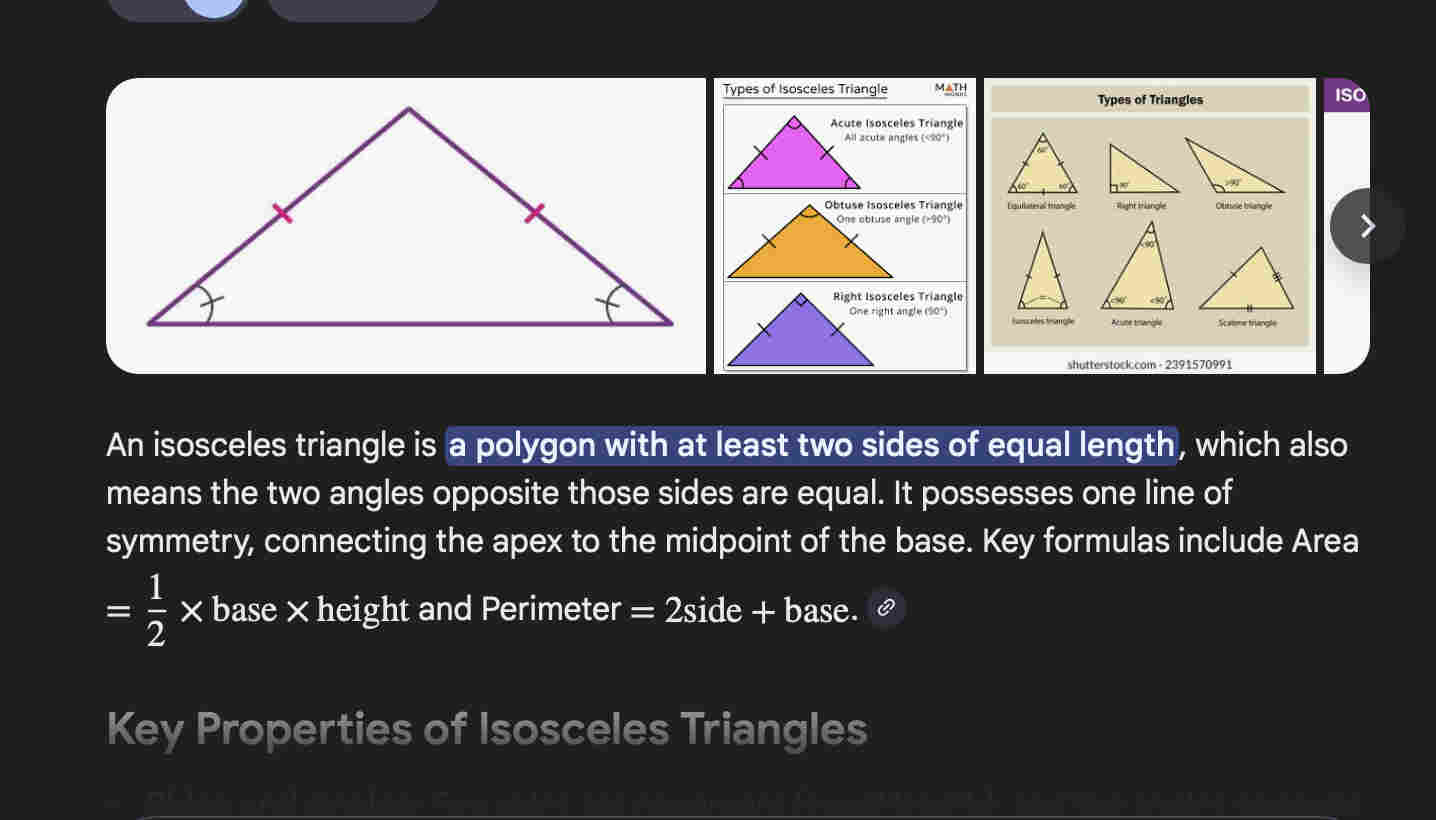
It suggested a isoceles triangle
For my caustics lamp my intitial idea was to use WASTE 3mm ply to create my base pieces and then stick reflective vinyl on them.
Without wasting much time and effort on thoughts and ideas, I decided to "think with my hands" and just start doing it
First step was to set all parameters on Fusion such that future edits become way easier (CAME VERY HANDY)
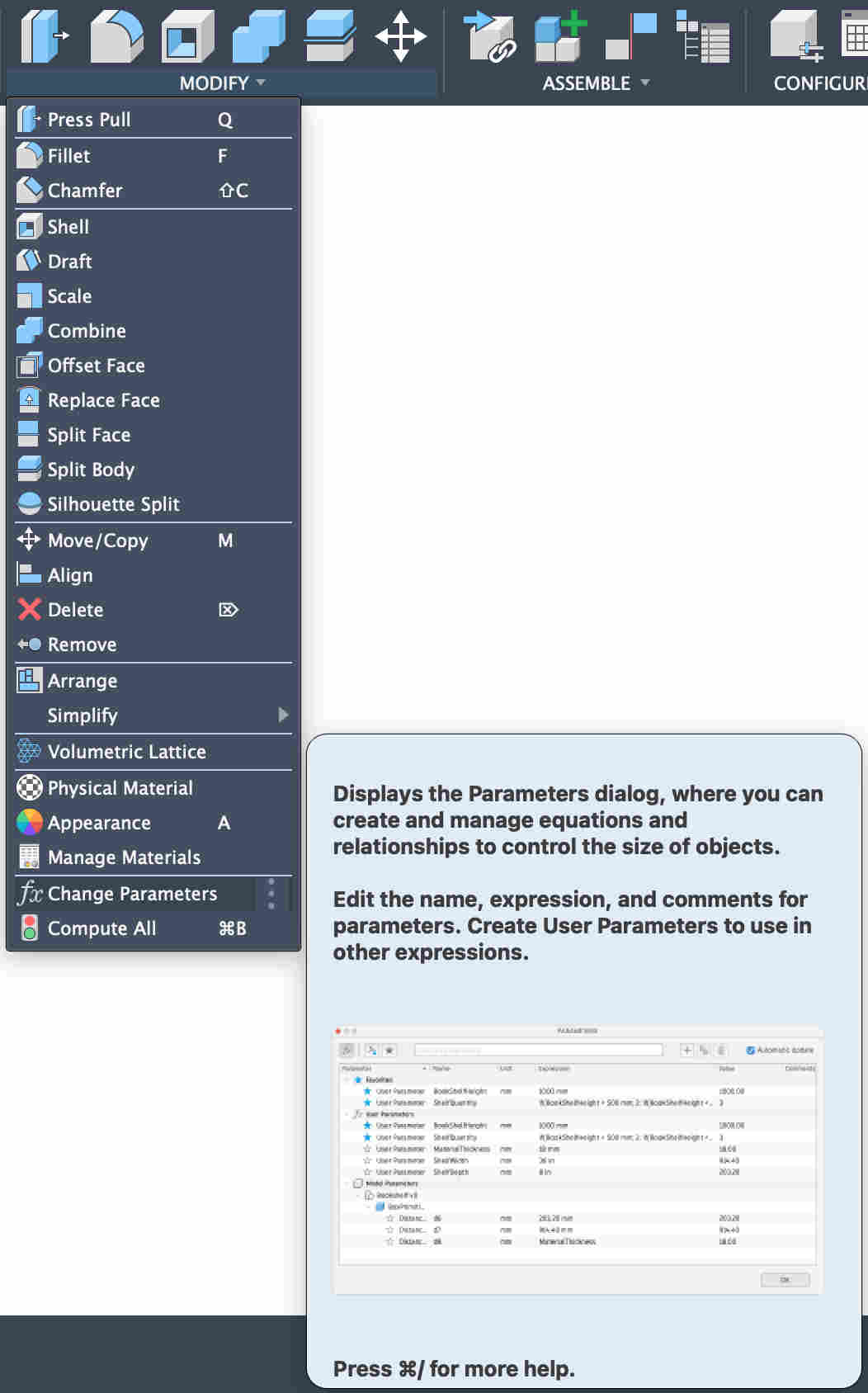
HOW TO
. Open fusion
. Modify on tool bar
. Change parameteres
WHAT ARE PARAMETRES?
To dumb it down- parametres are basically a value or a dimension that you preset and then reference that preset while you design SUCH THAT- once you change the paramtres (It's like a excel sheet) all changes happen co relatively by calculations
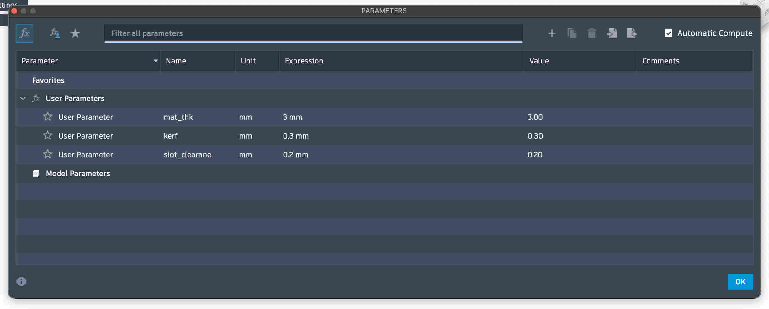
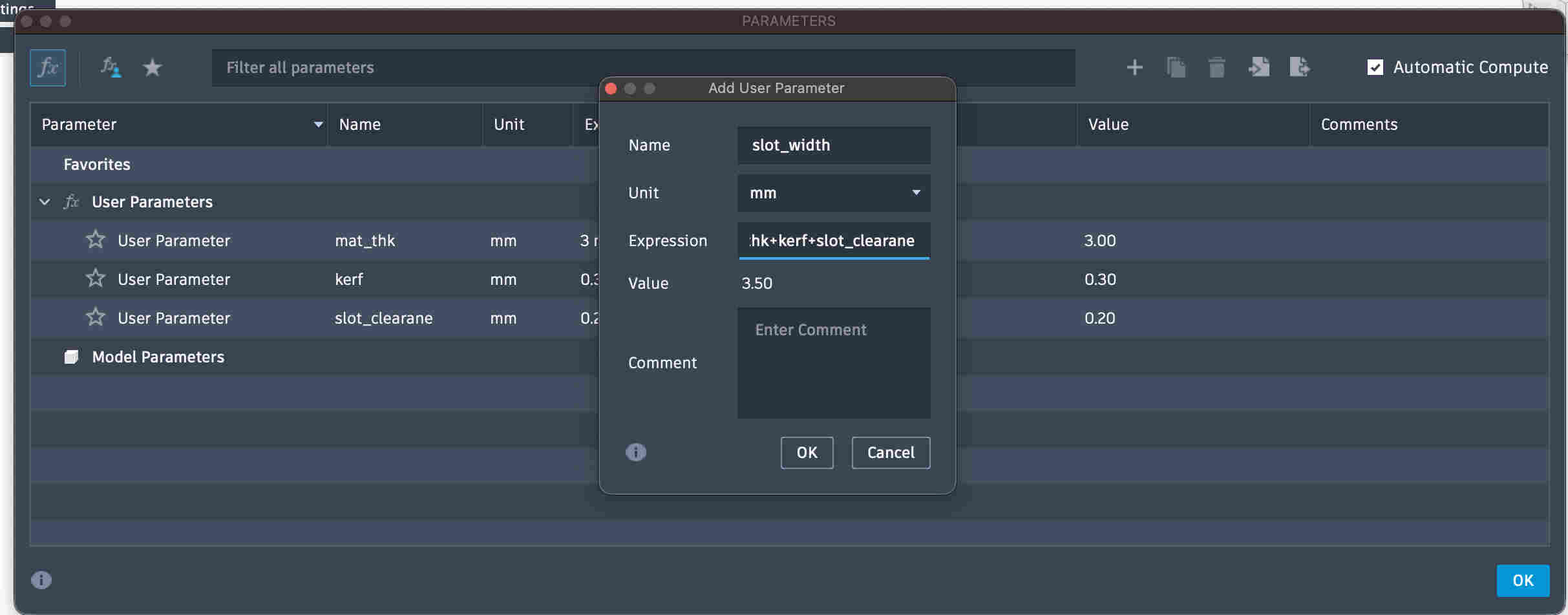
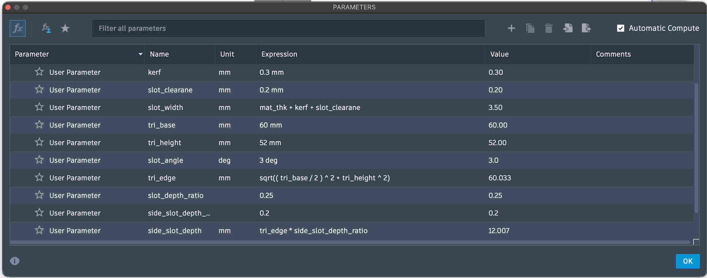
Add parametres ---- give them proper nomenclature ---- add units
You can also do mathematical operatiions with other parametres that you have already added as seen in the picture above
HERE- mat_thk + kerf +Slot_clearence
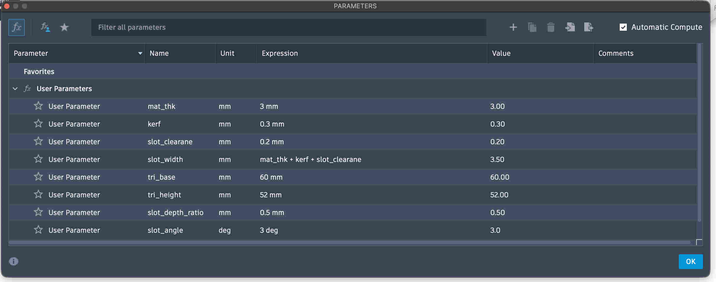
All parameters are added.
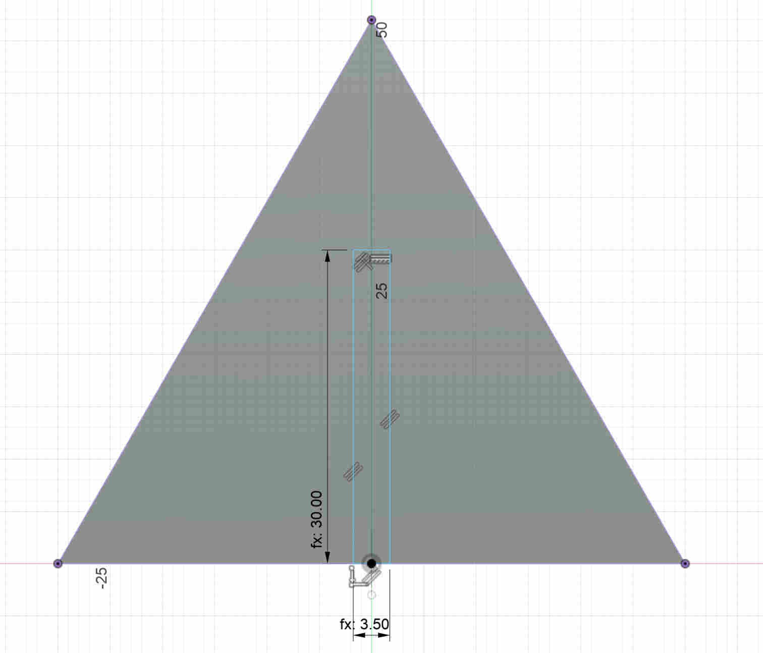
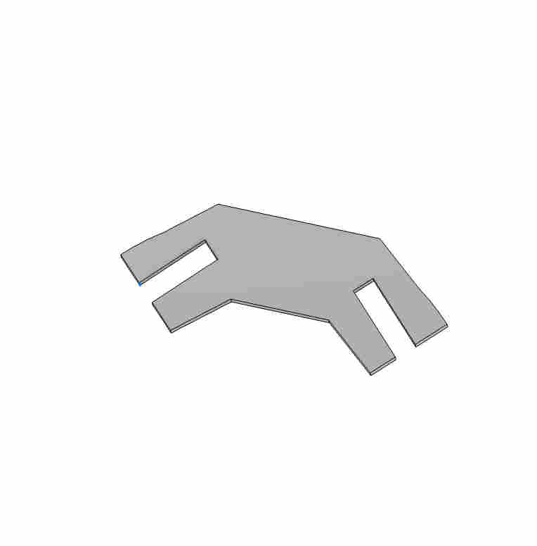
If you see most of my slot dimesnions are co-related to material thickness and base widtch or length. This enables me to change any major dimension, such as base or material thickness. and the slots and angles and hesigh will change
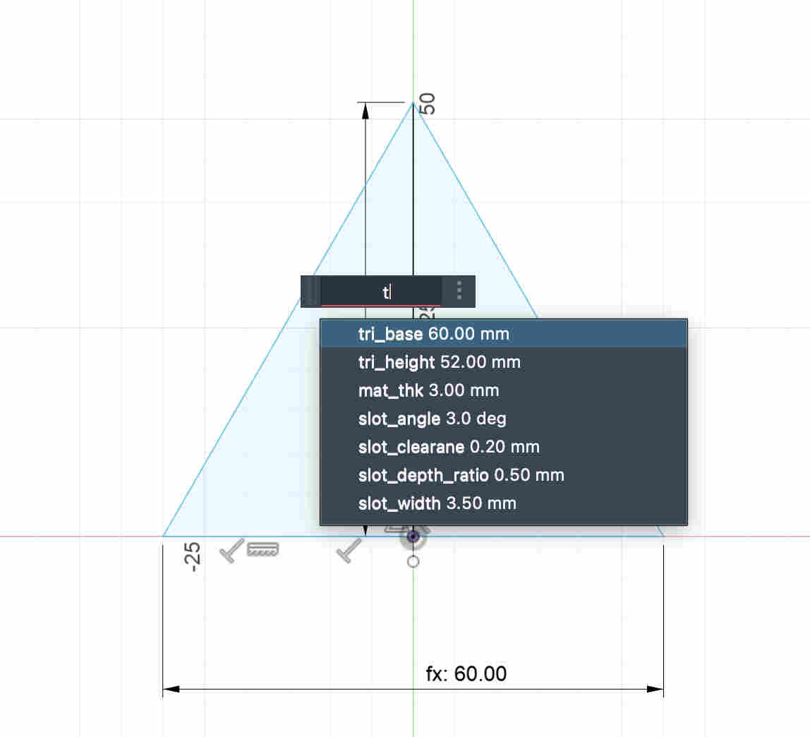
As you see, when you dimension it, you can name the parameters itself.
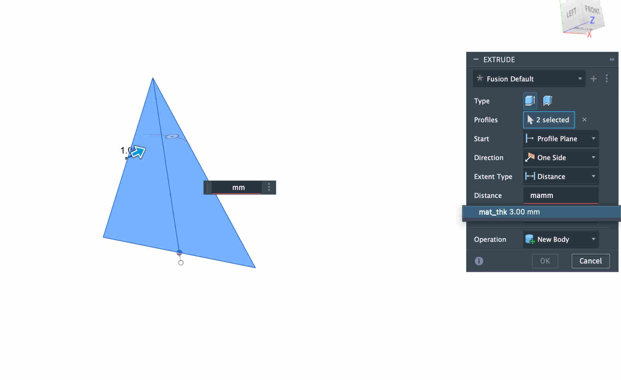
You can also use parameteres on commands
Parameterized slot dimensions.
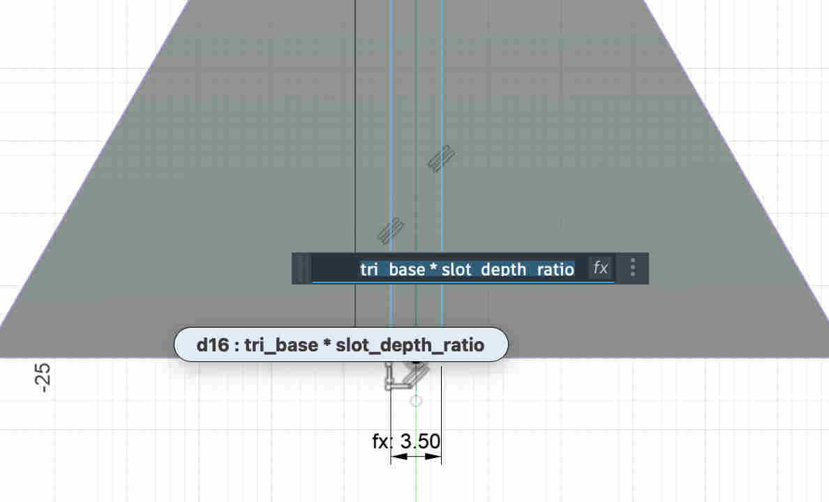
Instead of having hard parameter(slot_depth) with a hard value, I use a relation between the base and a ratio value.
WHY?
I do this because my slot depth now is dynamic, if I decided to change the base dimension in my parameters the depth will change relative to the base and not remain too short or too long
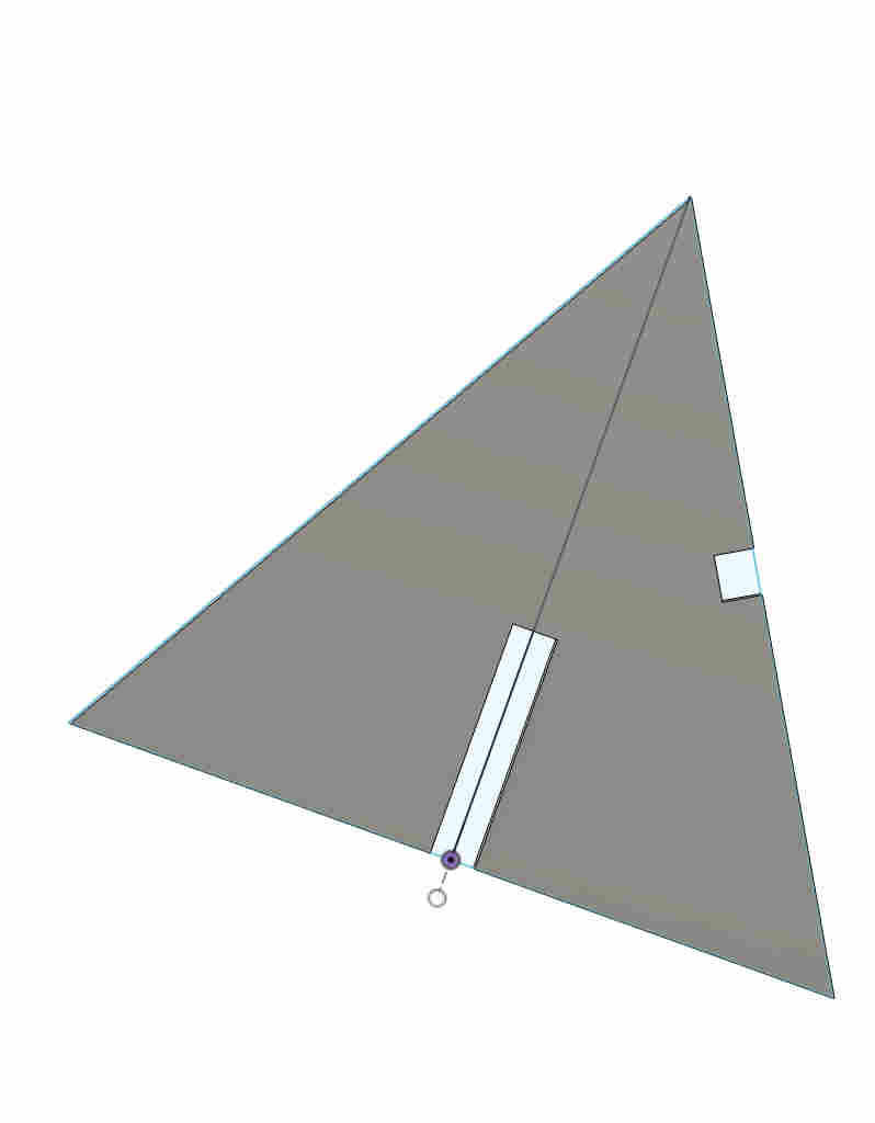
ERROR- My slot depth expression (tri_base * Slot_depth_ratio) was not working
This was because two united parameters cannot be multipliedAs you can see i kept the value with 'mm' unitsTo fix it- you can make the value UNITLESSAll parametersIteration 1First iteration cuts
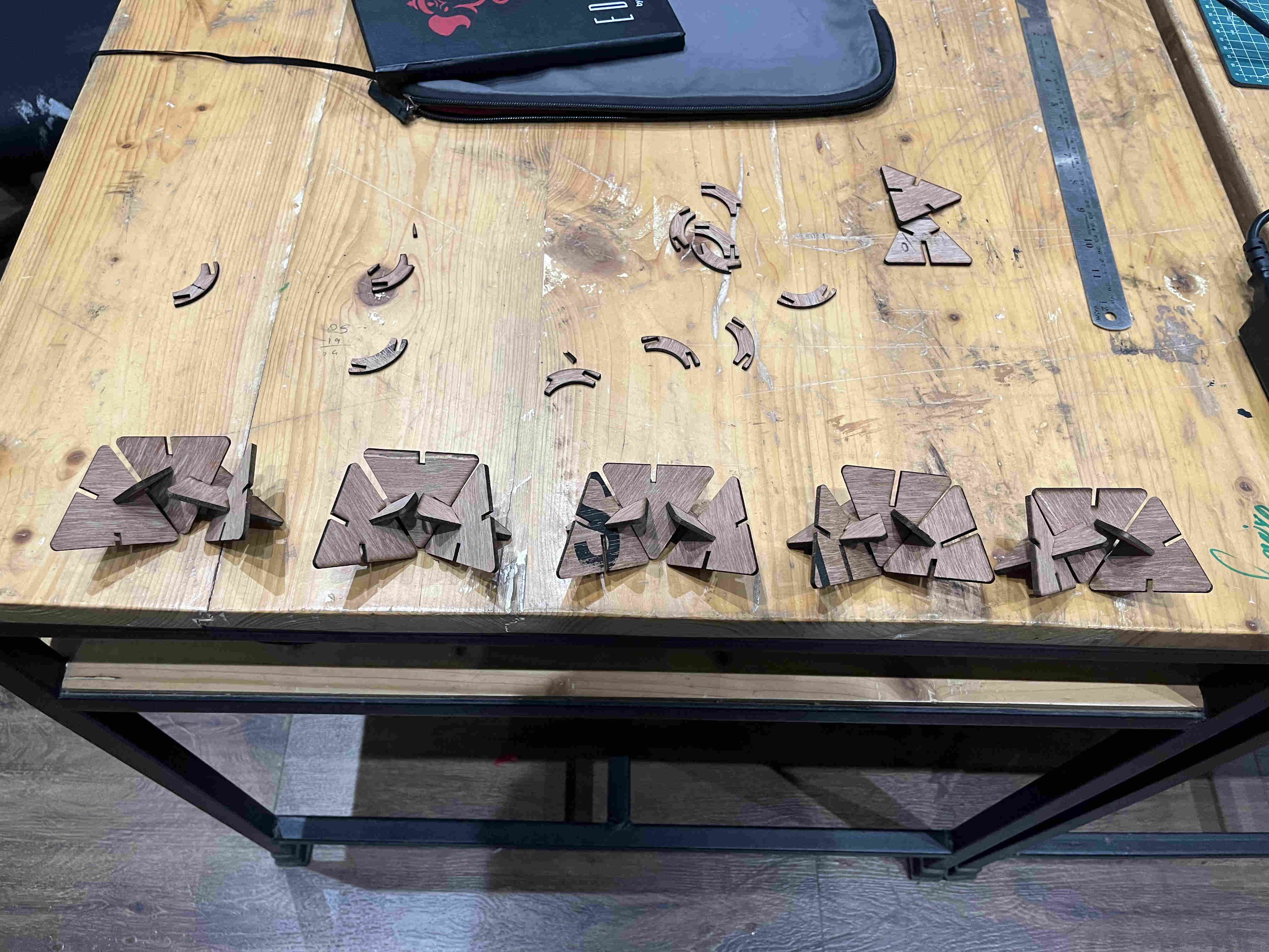
ERROR-
extrmely loose fits despite precise kerf measurement and slot clearance given
post calculation the slot width should ideally be around 3.3 mm but coming to around 4 mm After wondering if while assembling the lenses the focus had shifted, i realised my parameter expression was wrong. instead of subtracting my kerf values I had added it Once my slot thickness was correct i started cutting pieces and eith various slot placements and depths and started exploring forms
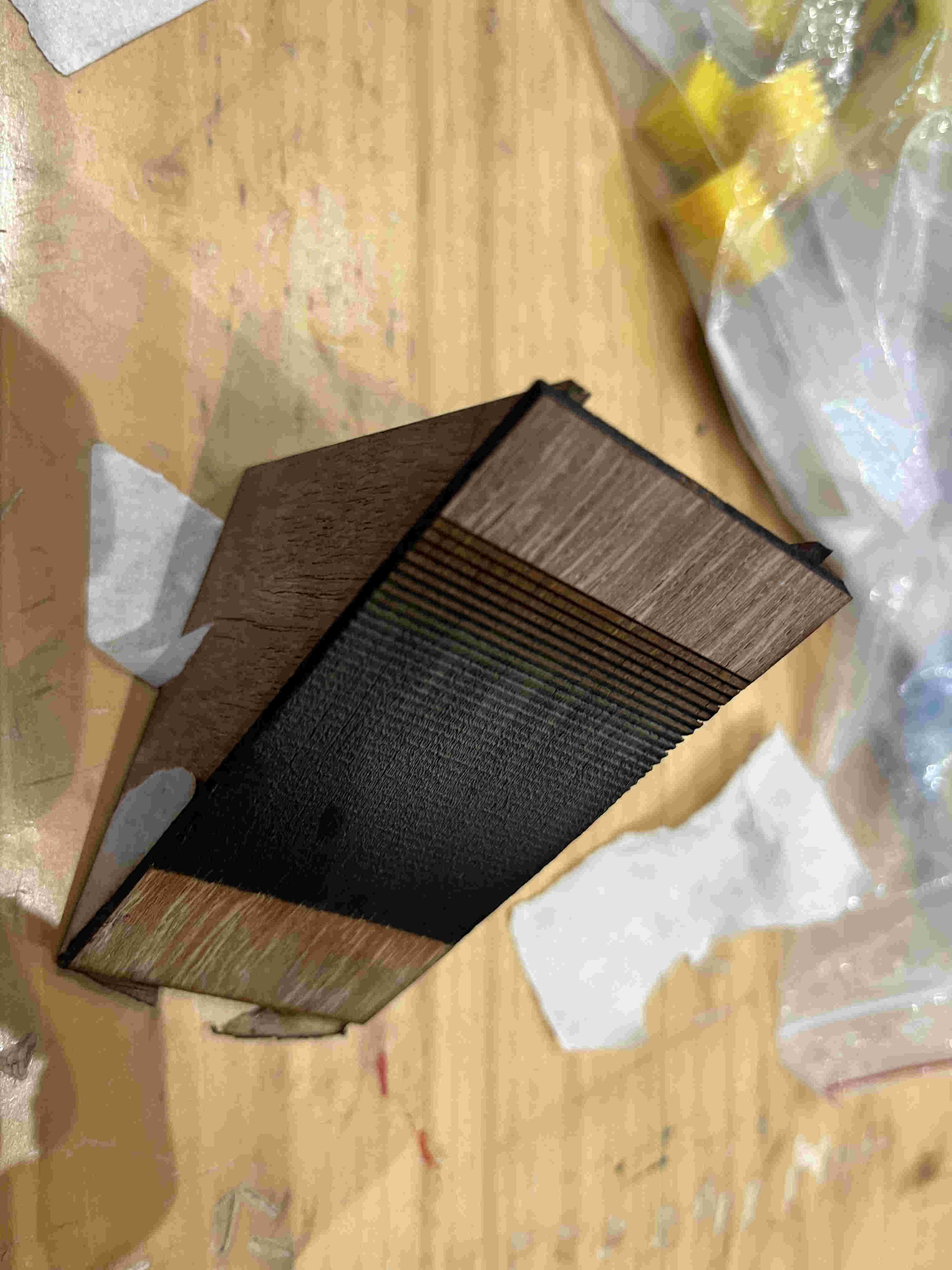
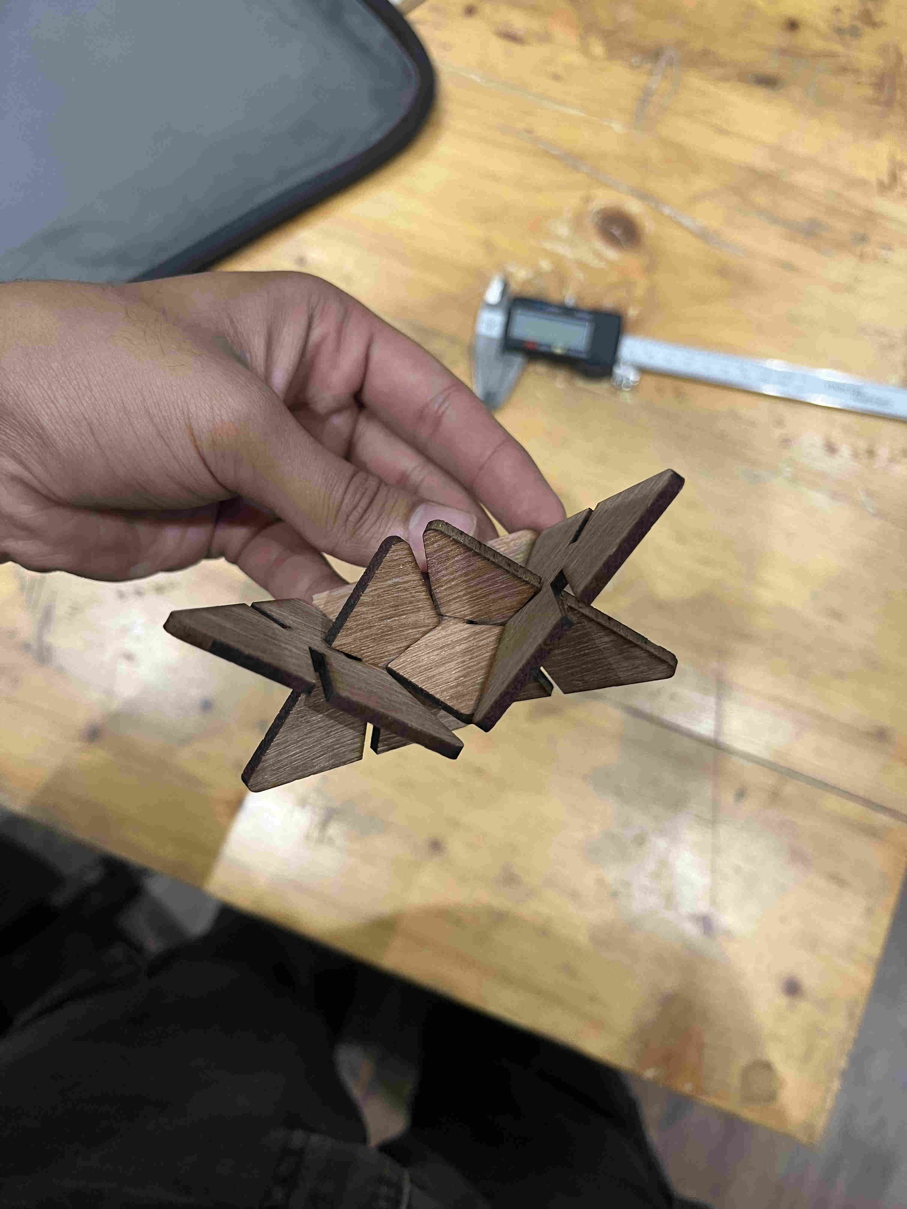
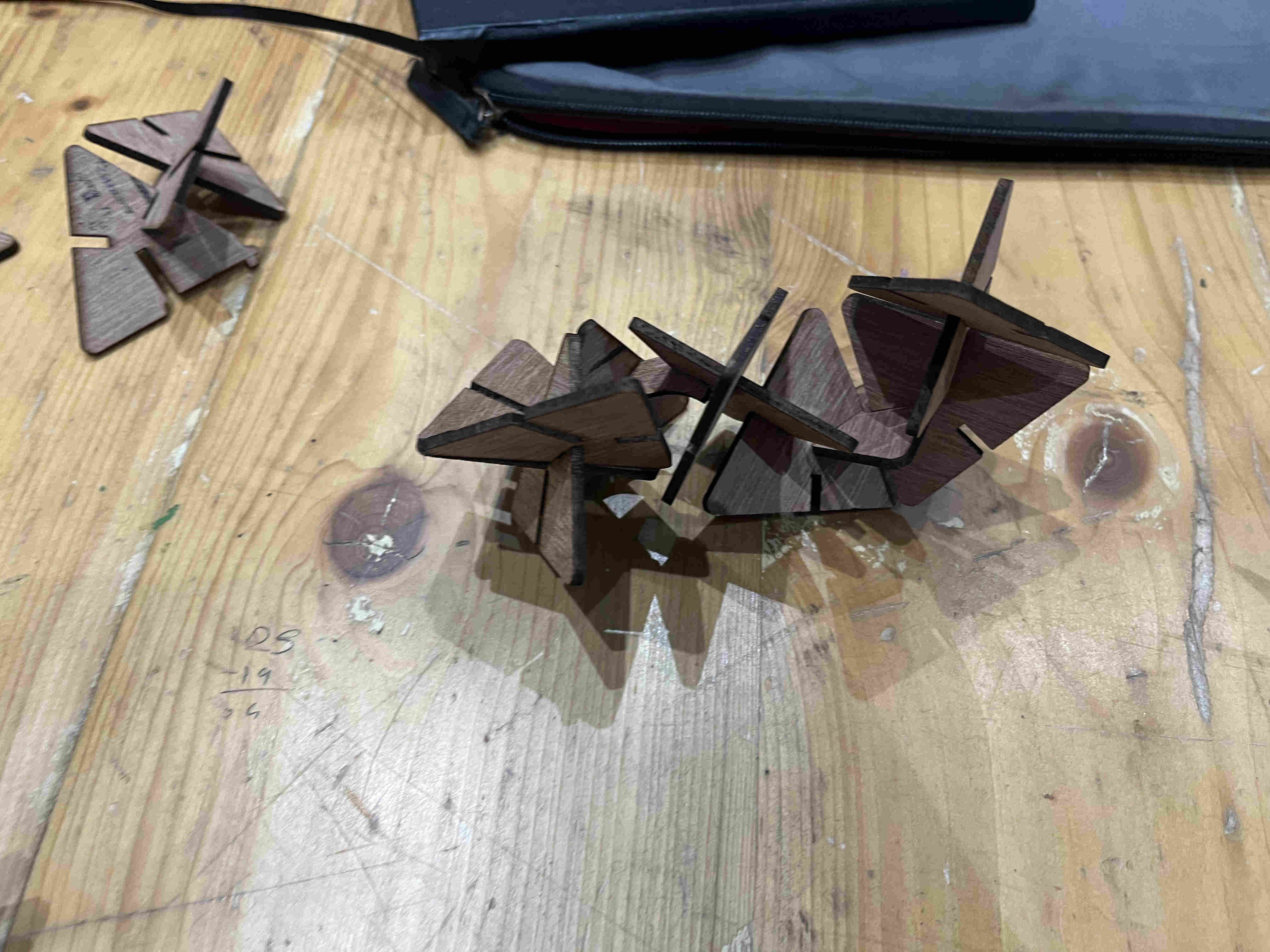
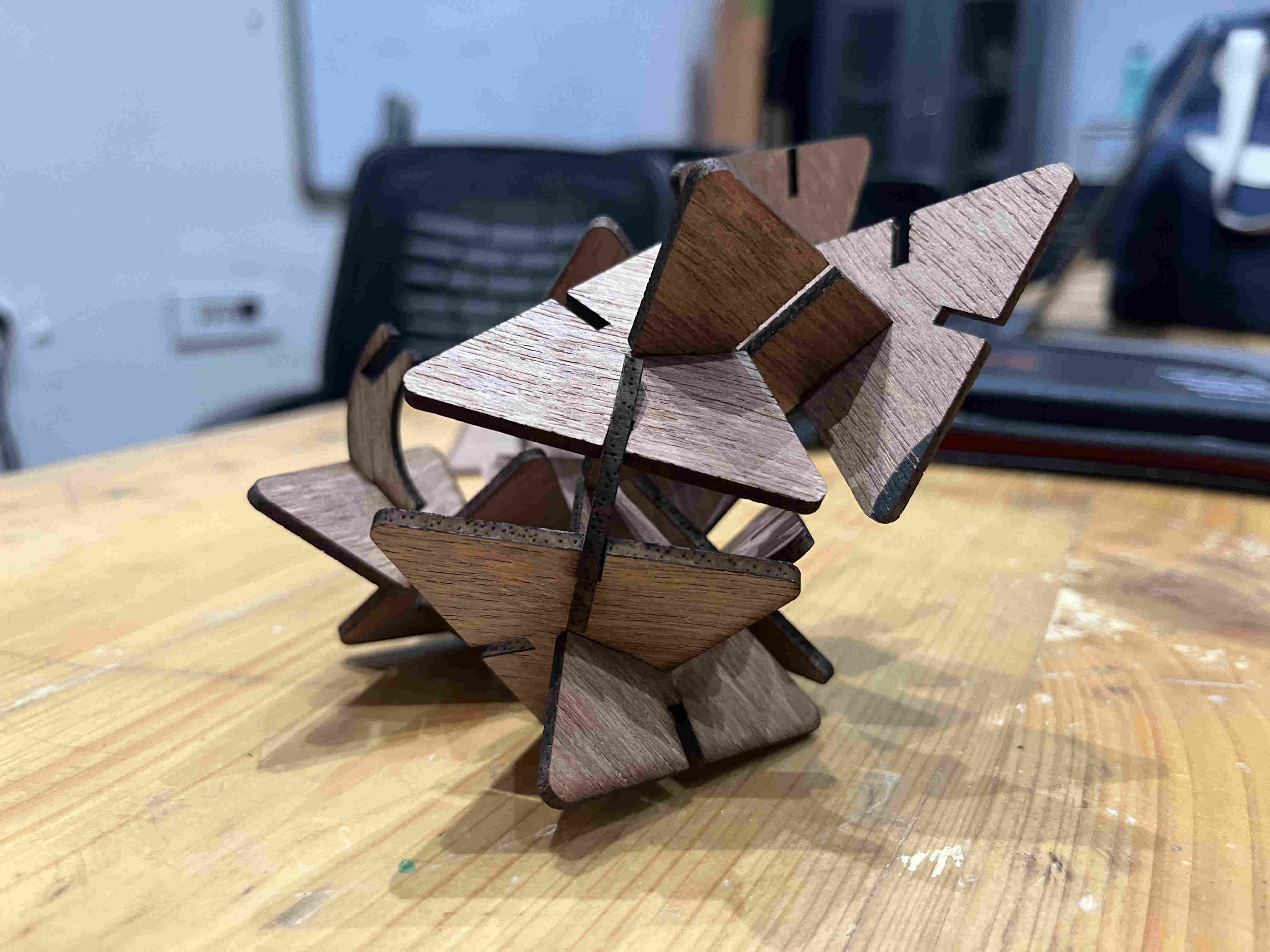
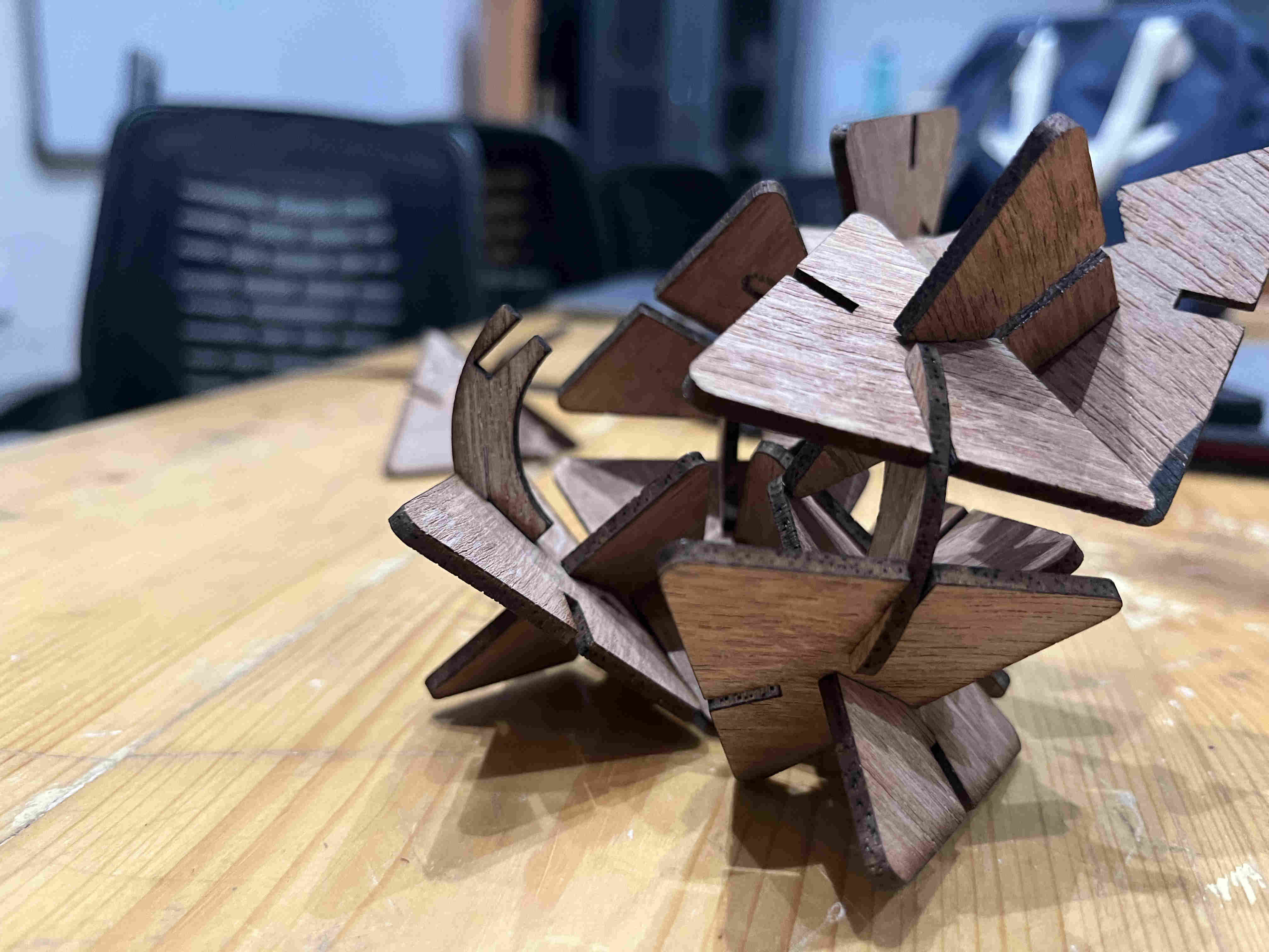
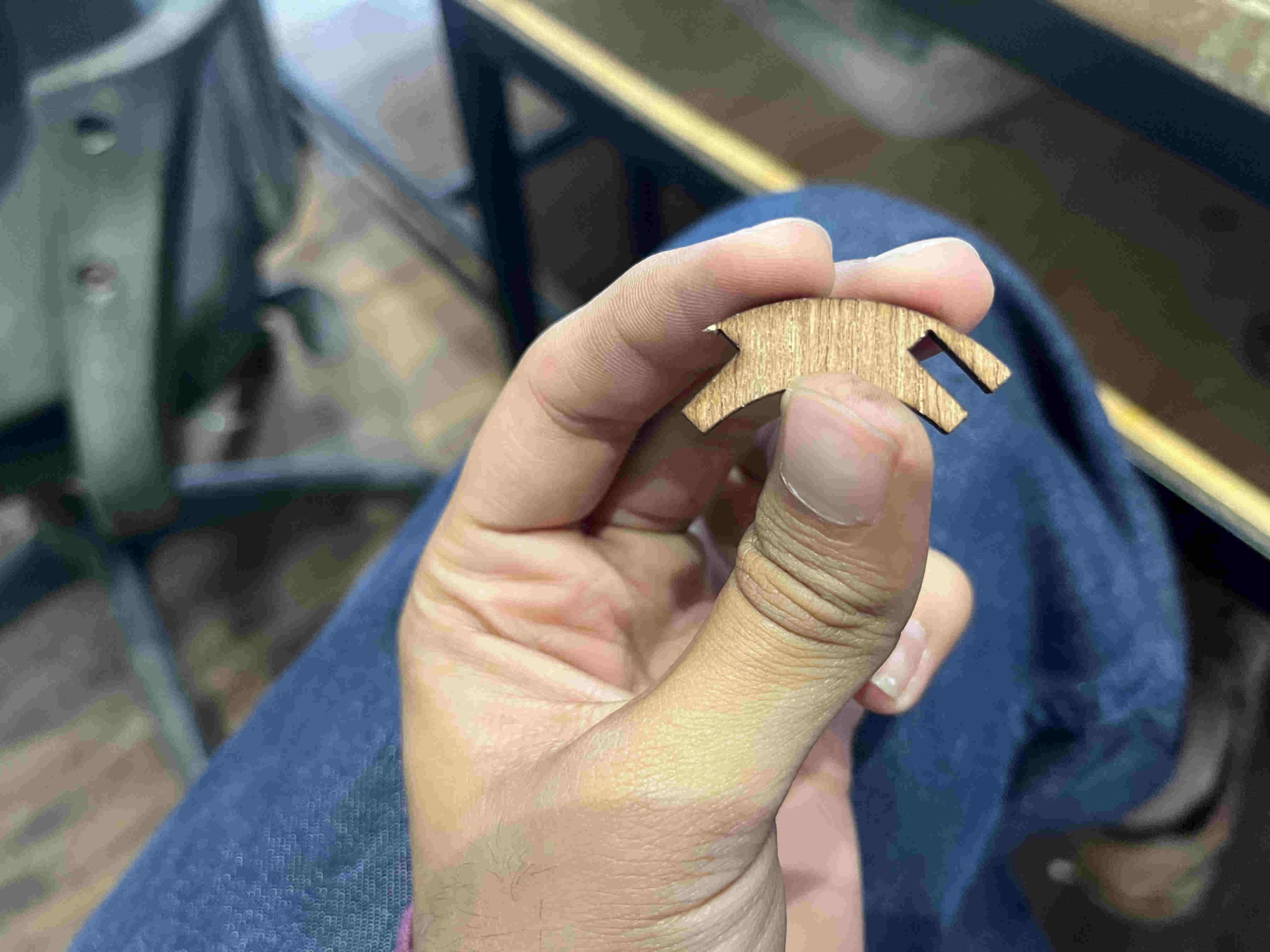
All of experimentation AND final project for this week is being done by using WASTE material..
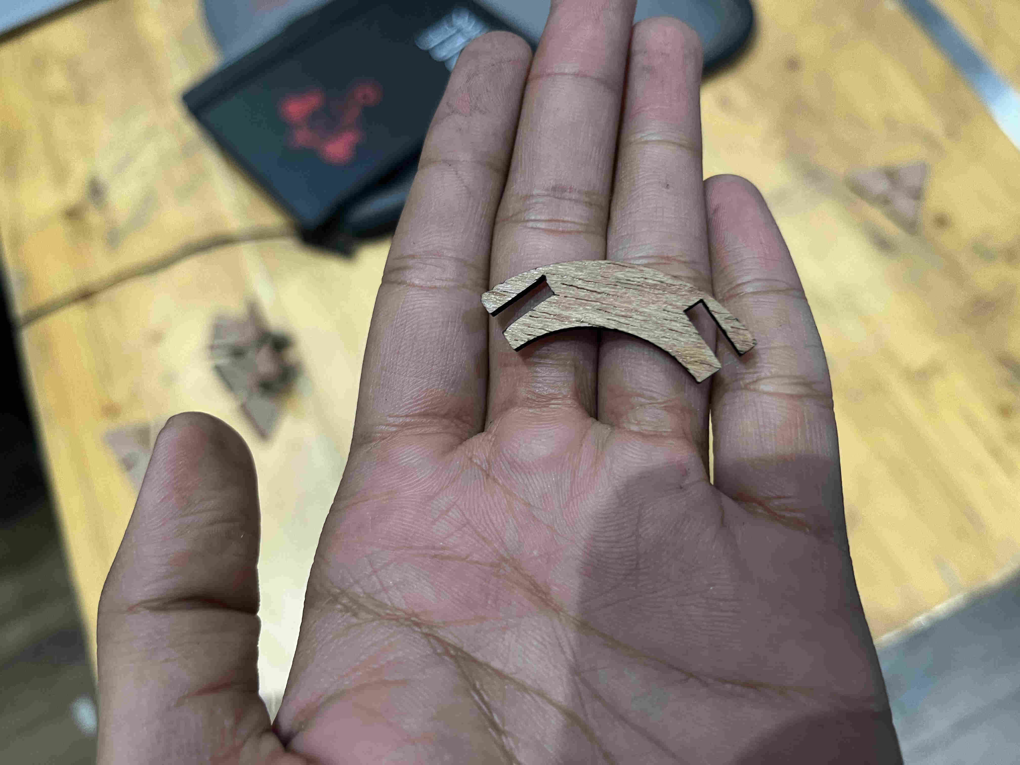
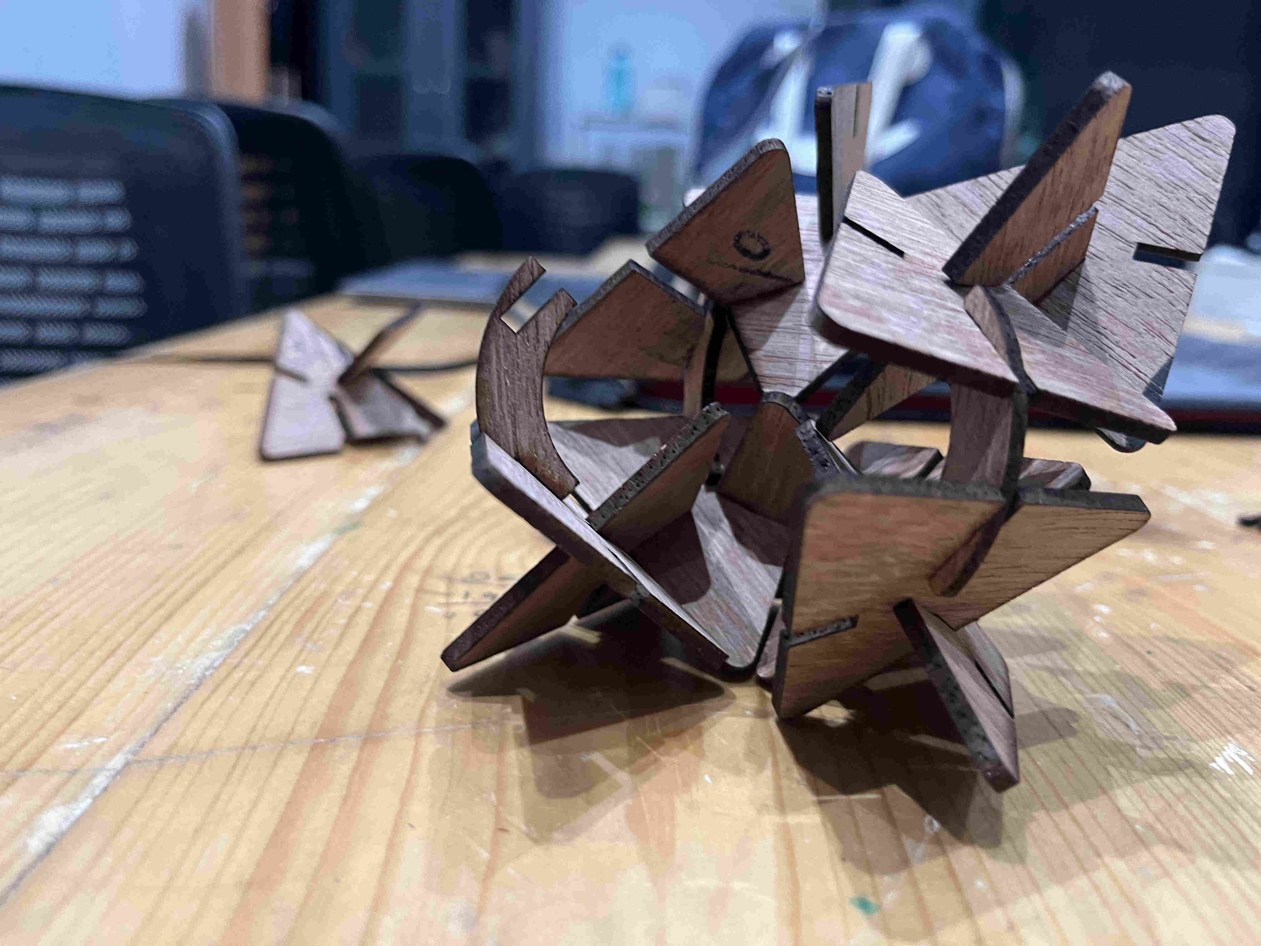
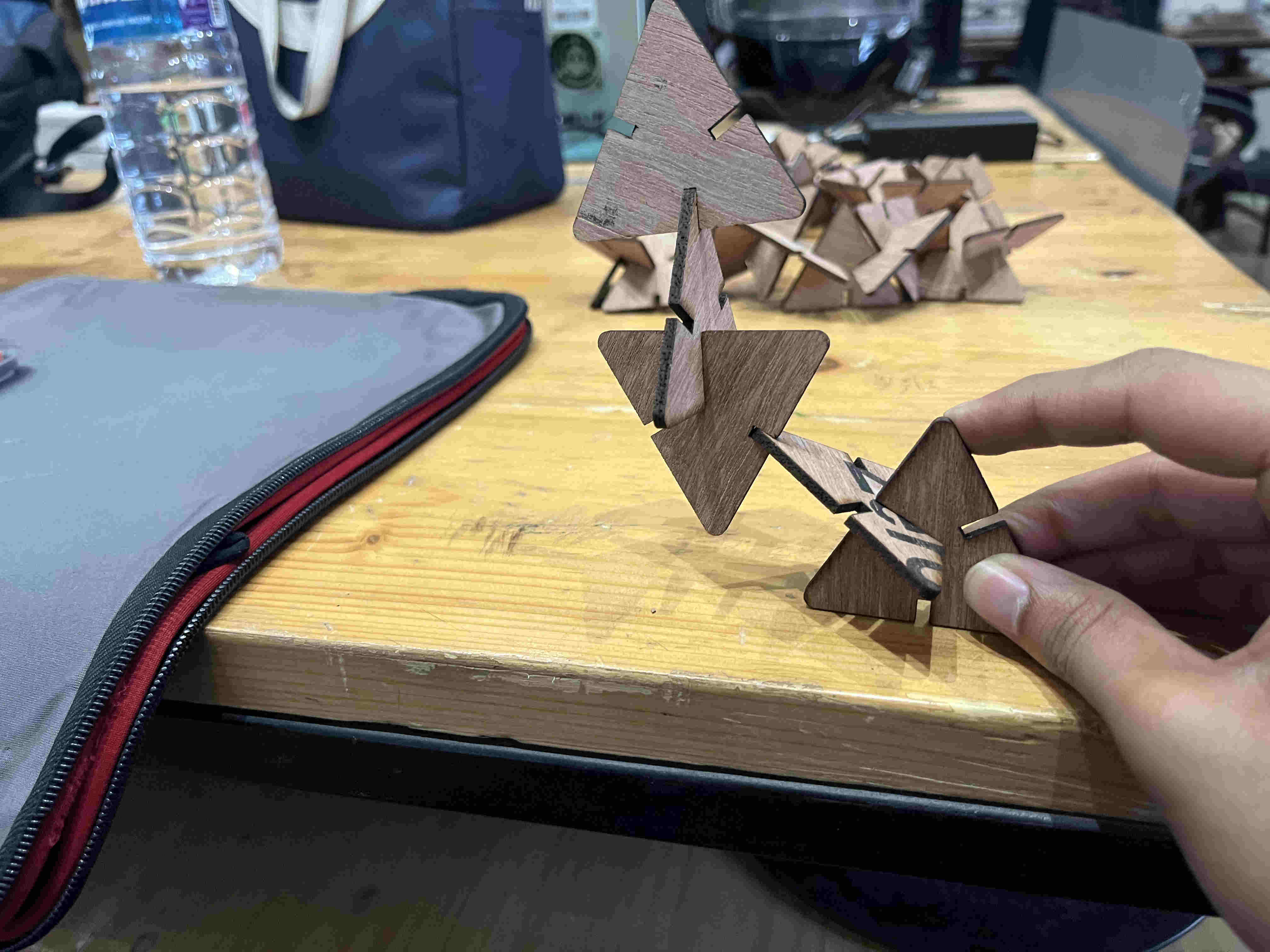
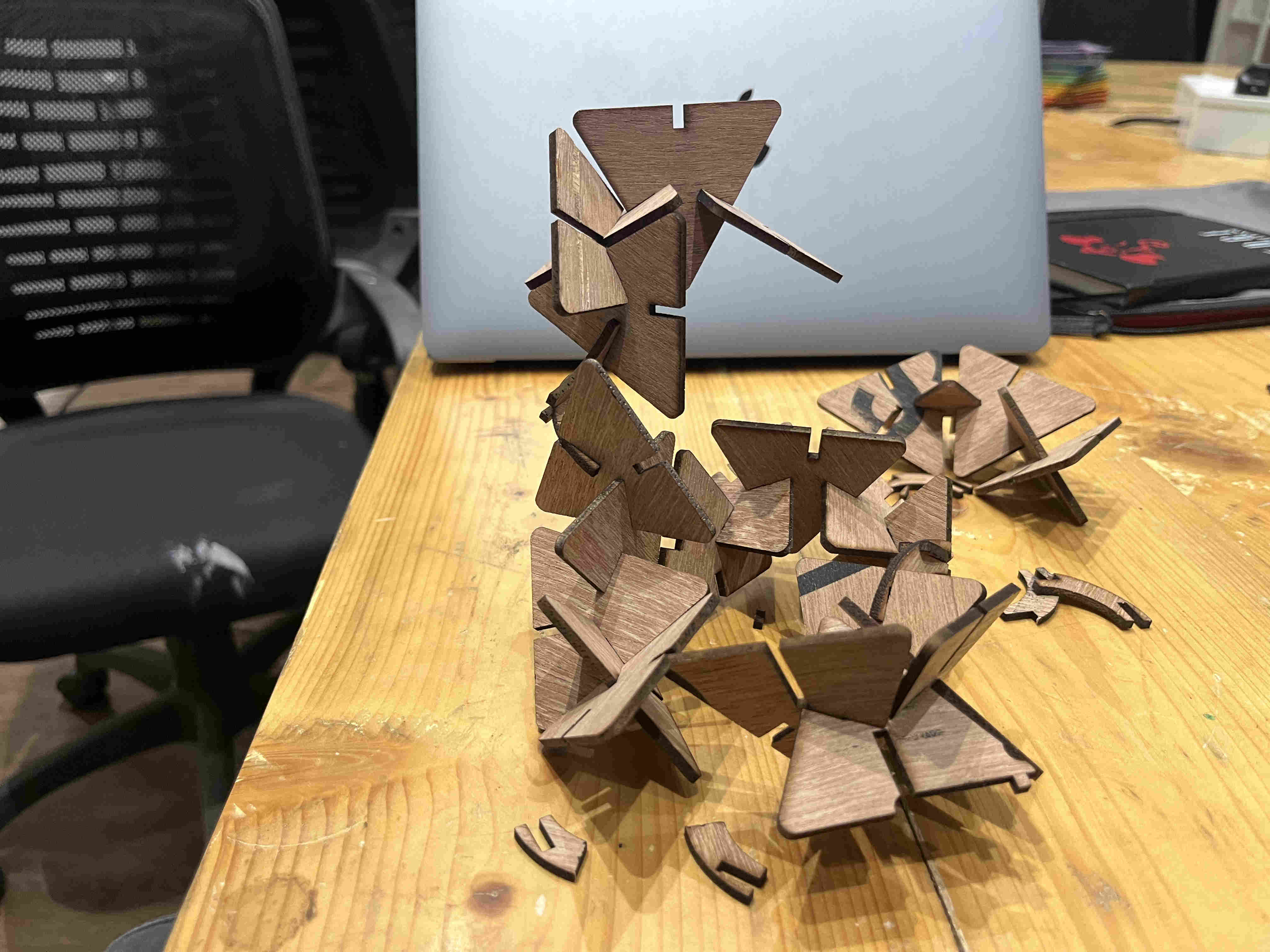
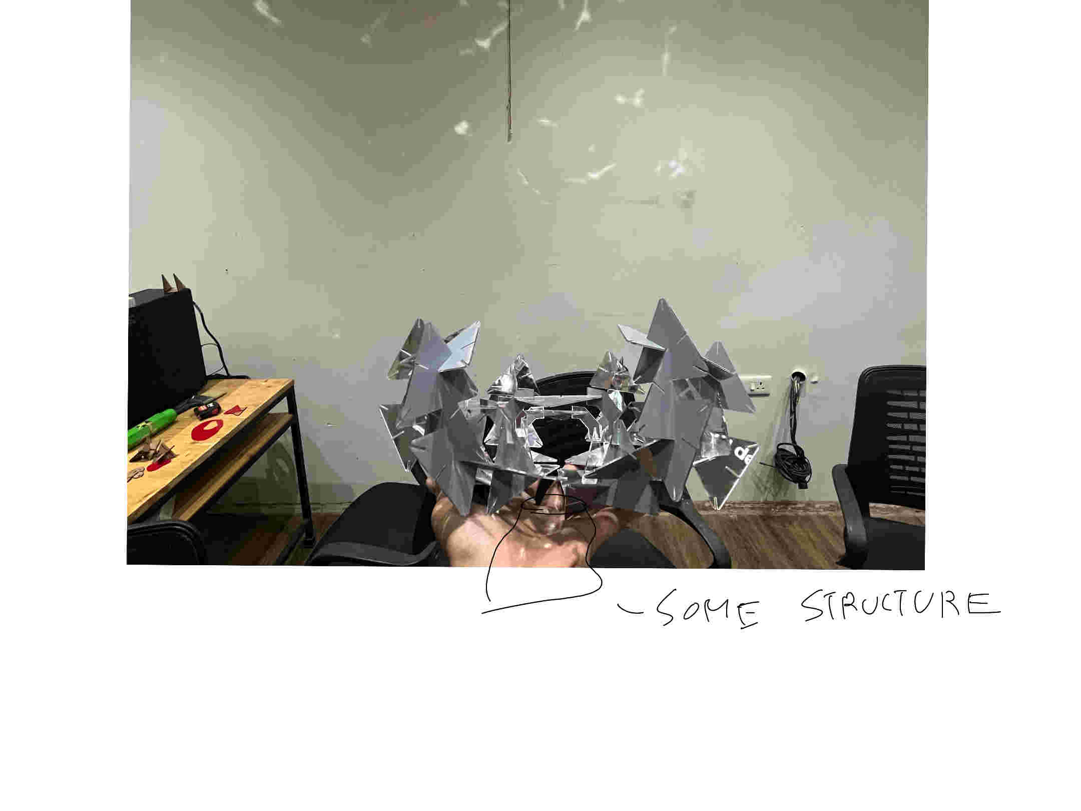
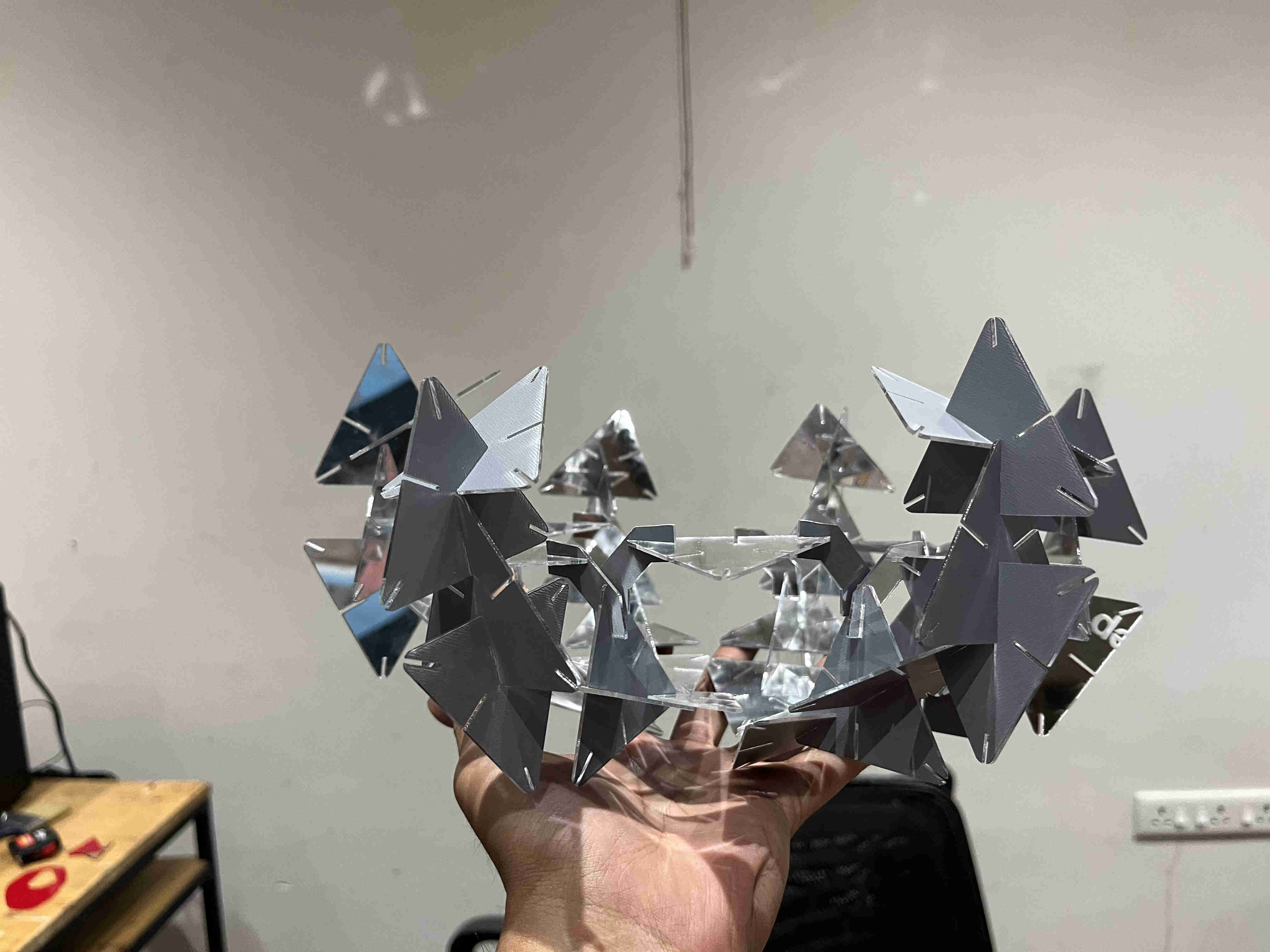
My plan was to create one basic intriguing form and then repaet those structures around a perimeter using joints First Trial joint I started exploring and trying out forms with added complexity of joints to see what pans out. Initially finalised on this basic shape Tried a inclned profile that i could create multiple of and revolve around a centre to create a dome like structure My joint was designed poorly with a thin edge causing them to break pretty easily Redesigned and fixed this flaw (adds on to the fractal feel as well) First self inclining and stable structure
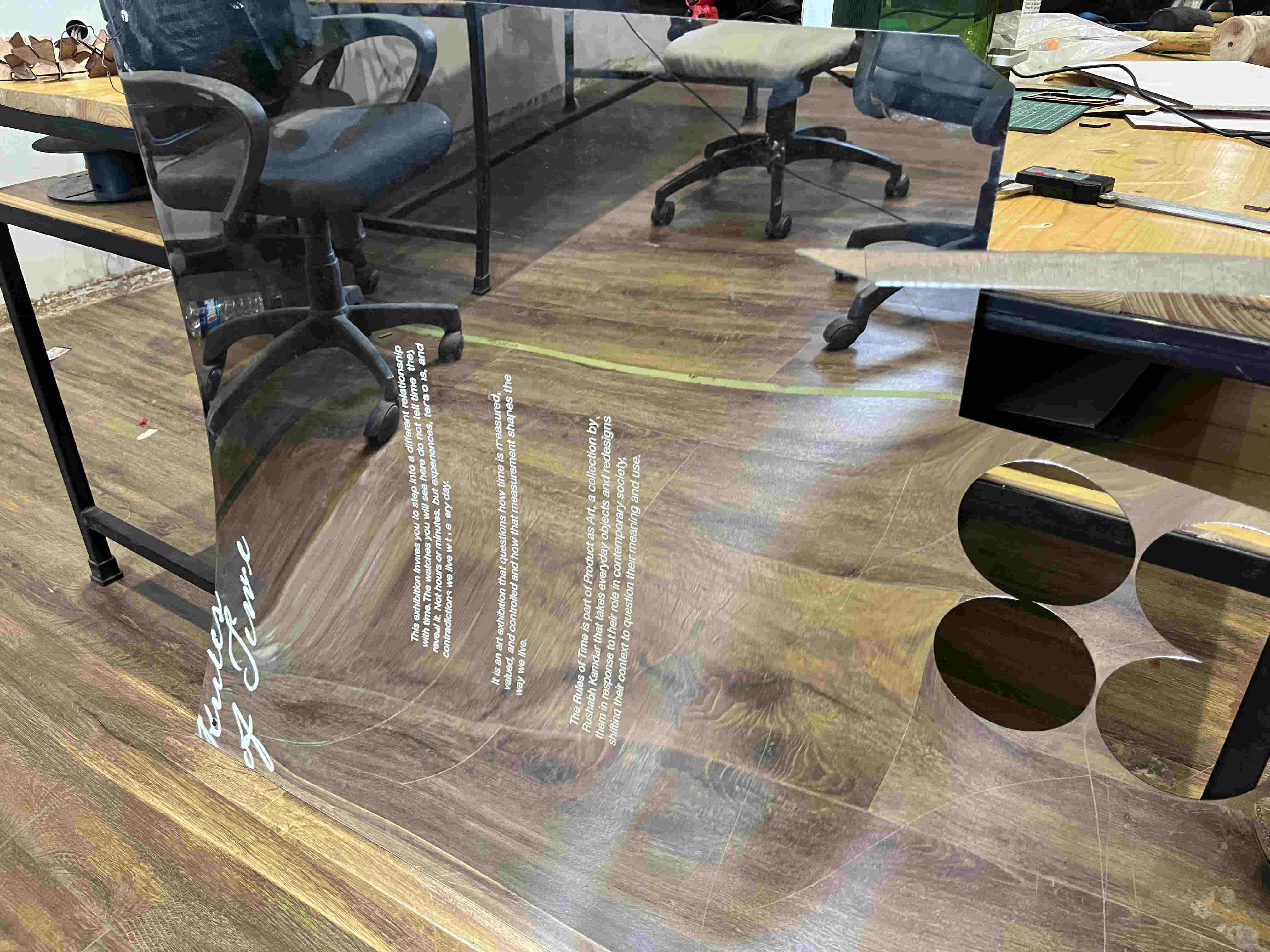
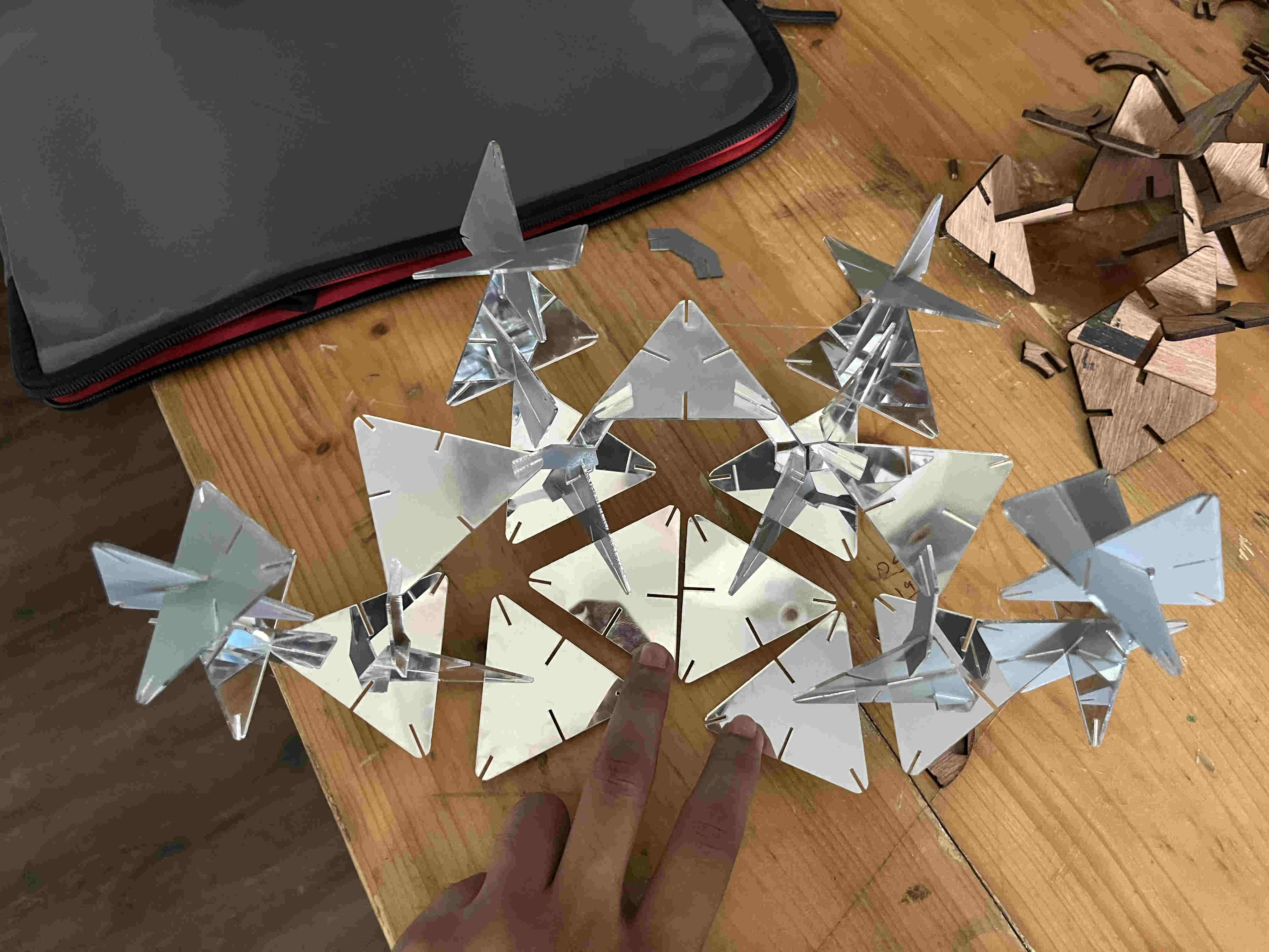
After having some idea of what i can do, my entire idea of caustics will have to be done after vinyl cutting and sticking each piece on indiviudal modular units, which would be tedious, and i had less time, i decided to change materials.
I luckily found some used reflective acryllic, i decided to use some of the used side for my project making it easier Since i had parameterized well, all i had to do was change material thickness(as acryllic was 1.2mm in thickness) and all my slot dimensions changed in relation to the thickness change
parameterize well, it saves tonnes of time
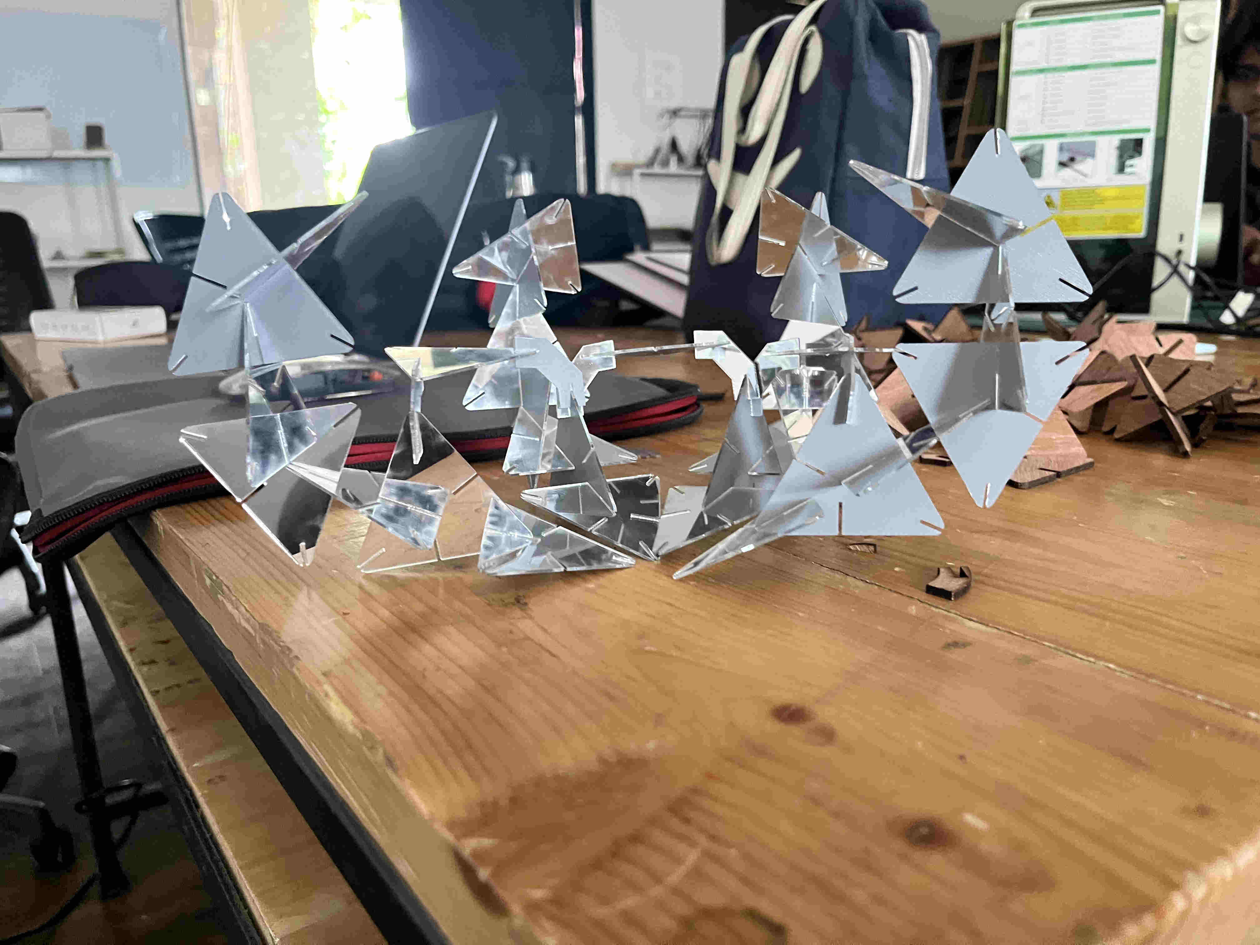
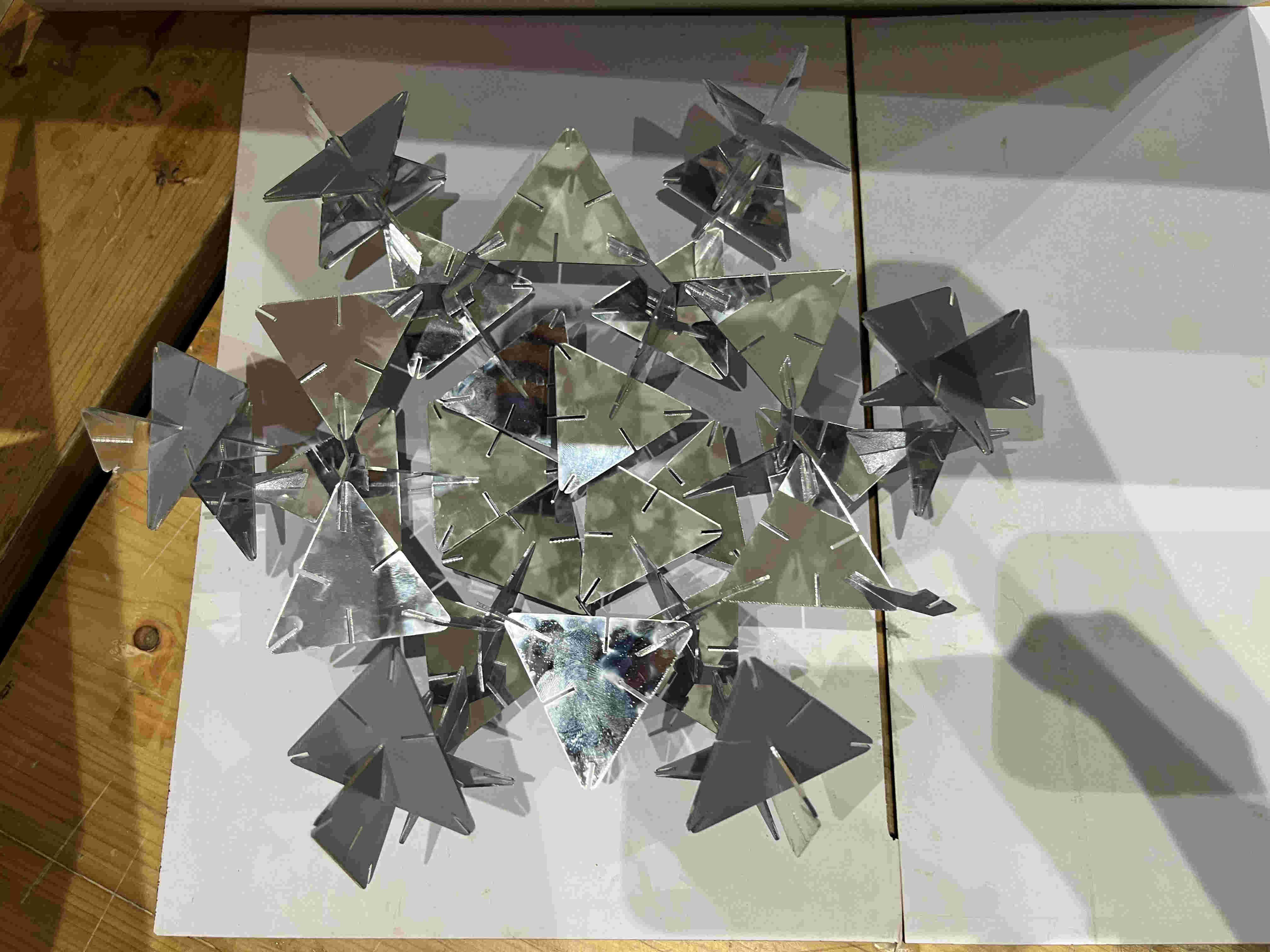
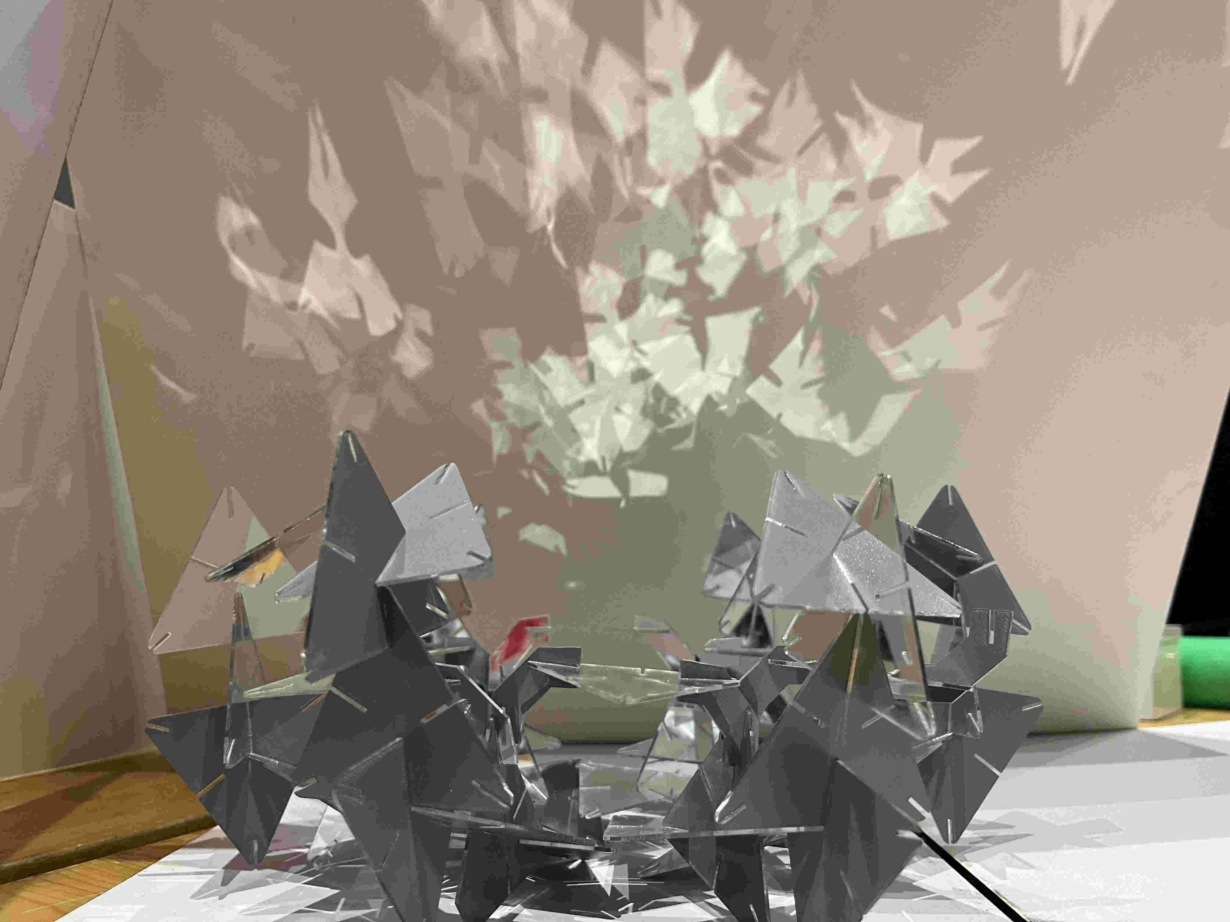
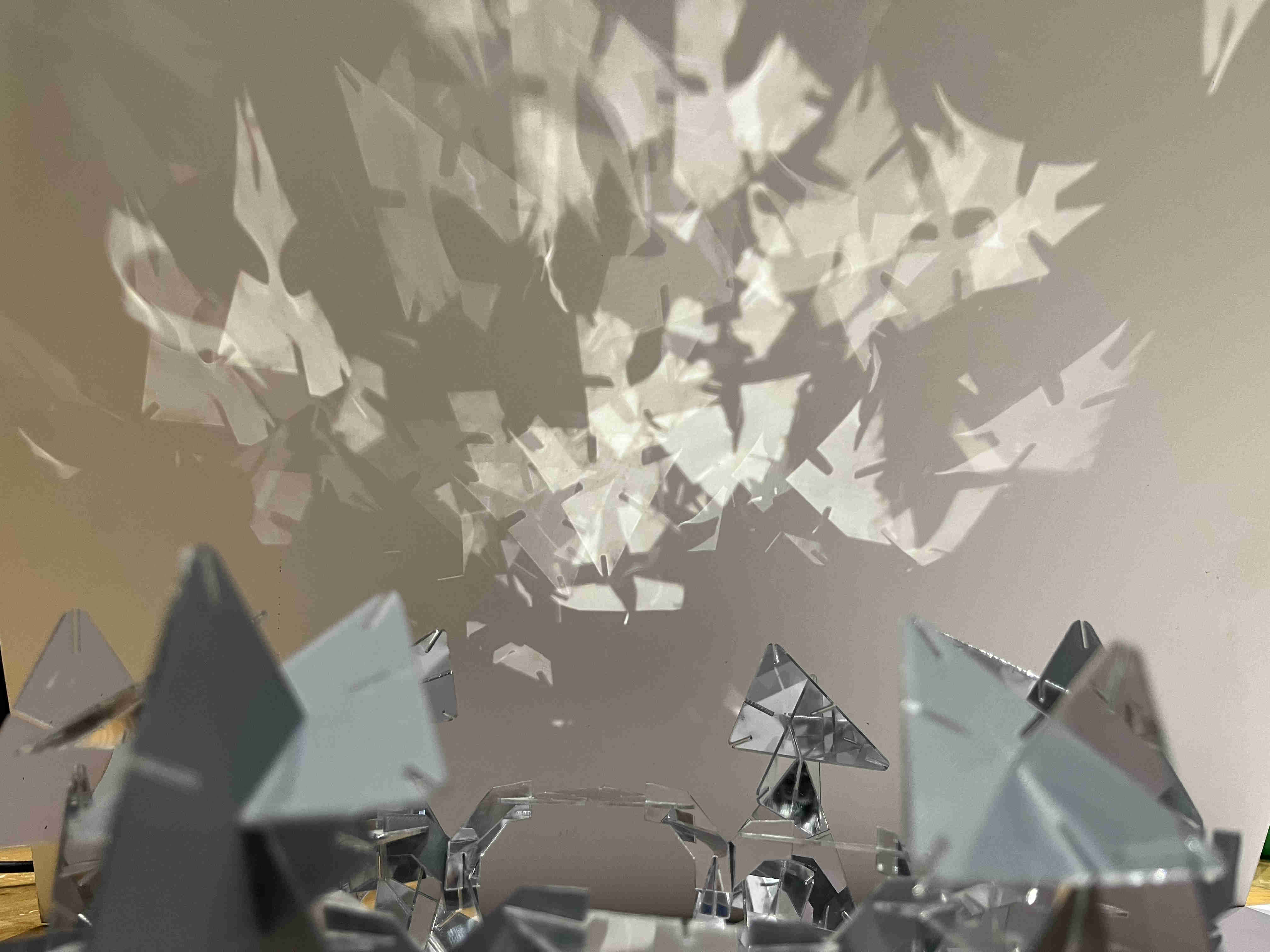
Found out the optimum power and speed for test cuts.Partial final resultfractal reflections Final formreflections wall point source Final design is intended to be with a point source lightreflections The form felt jarring to the eye, the form had no flow, i thought another element along with it woudl work great
Exploring what other element led me to auxetics
Hero shots
Interesying reflections
.Auxetics.
what is auxetics?
Basically, auxetics is a method of smartly cutting a material, such that when stetched, it doesn't thin, rather it expands. they are also called metamaterials
https://youtu.be/2tKj7wQtXxYAbove is a comprehensive video showing metamaterialsshort video showing one type of auxetic (rectangular auxetic)My attempt at metamaterials was completely from a blank slate, i did not know how any of this works
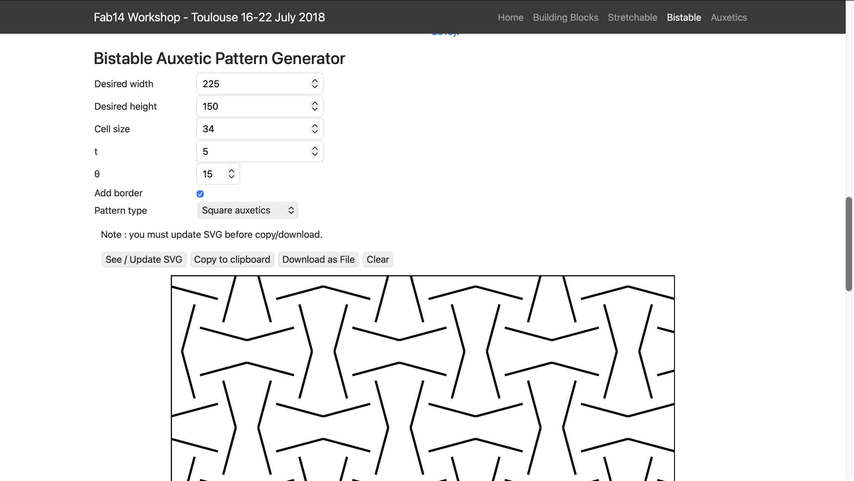
luckily an awesome resource popped up when I search auxetics on the google powered search bar on the fab page.
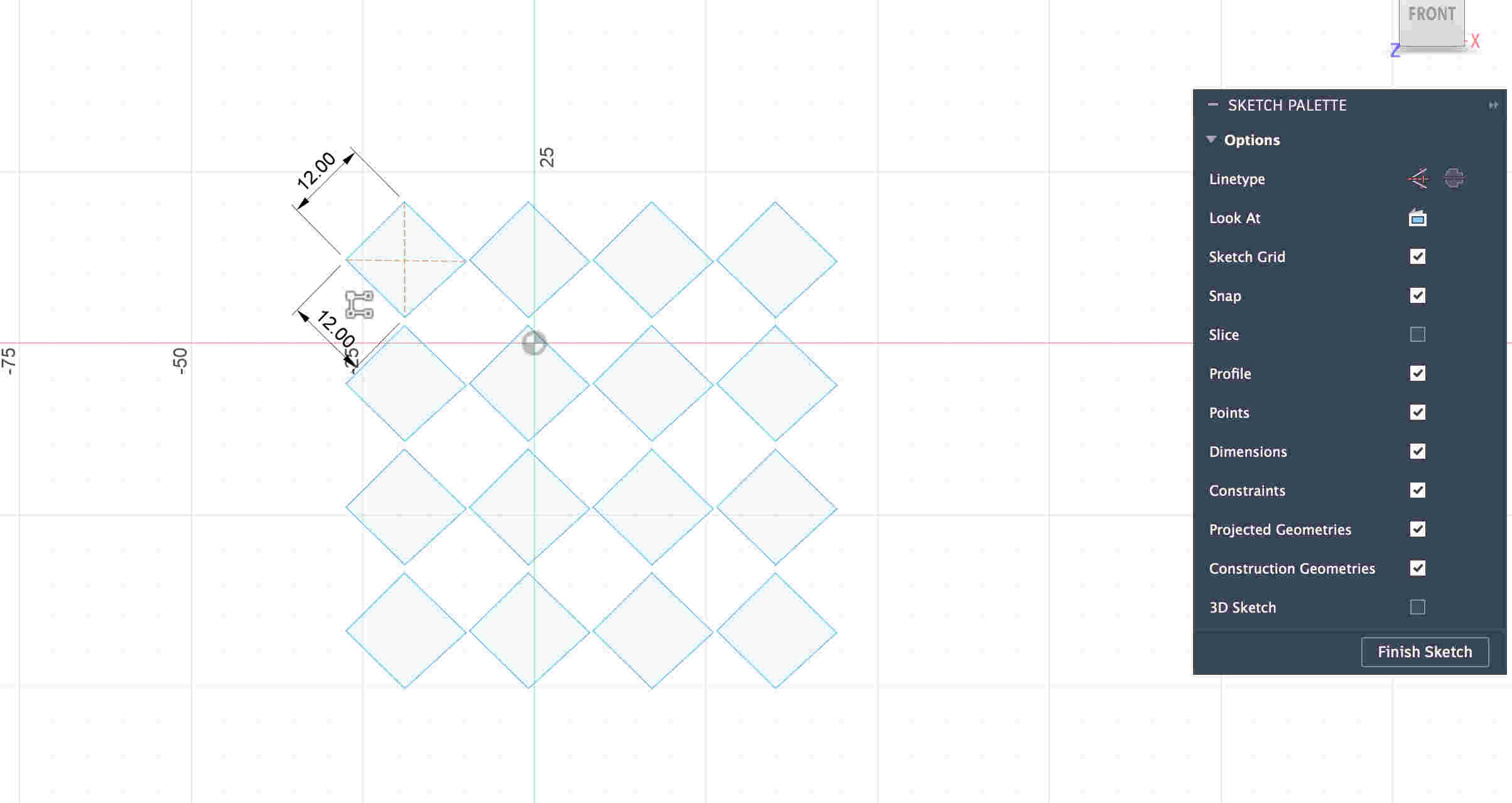
Here I could put specific parameters and choose between two types of cuts and export it as svg. WHAT A SAVIOUR
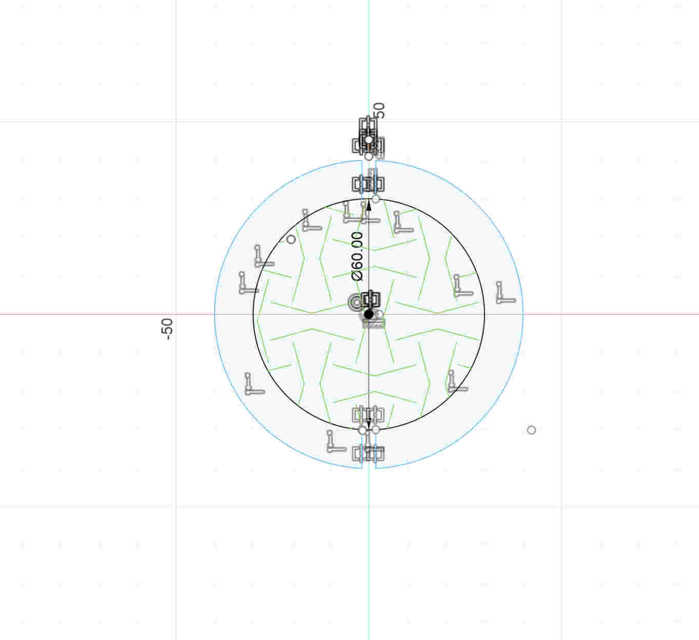
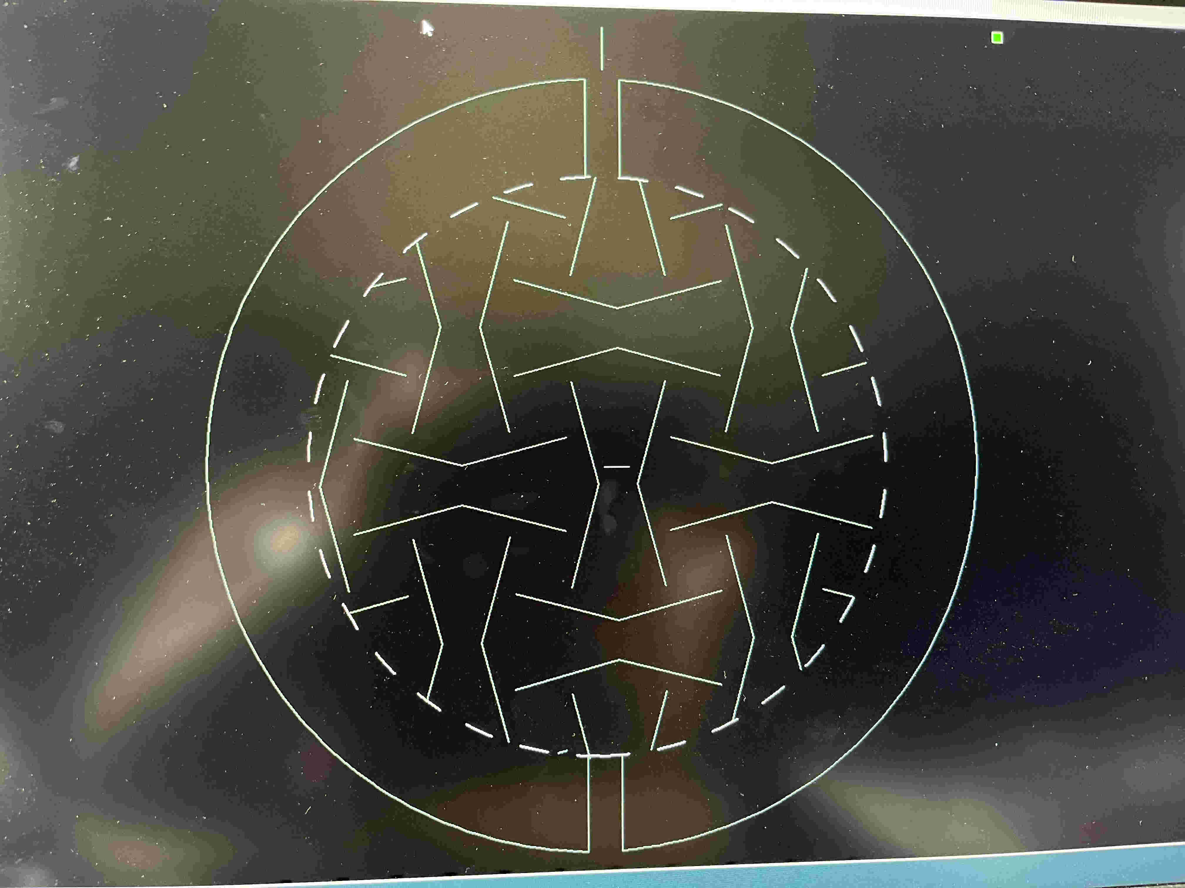
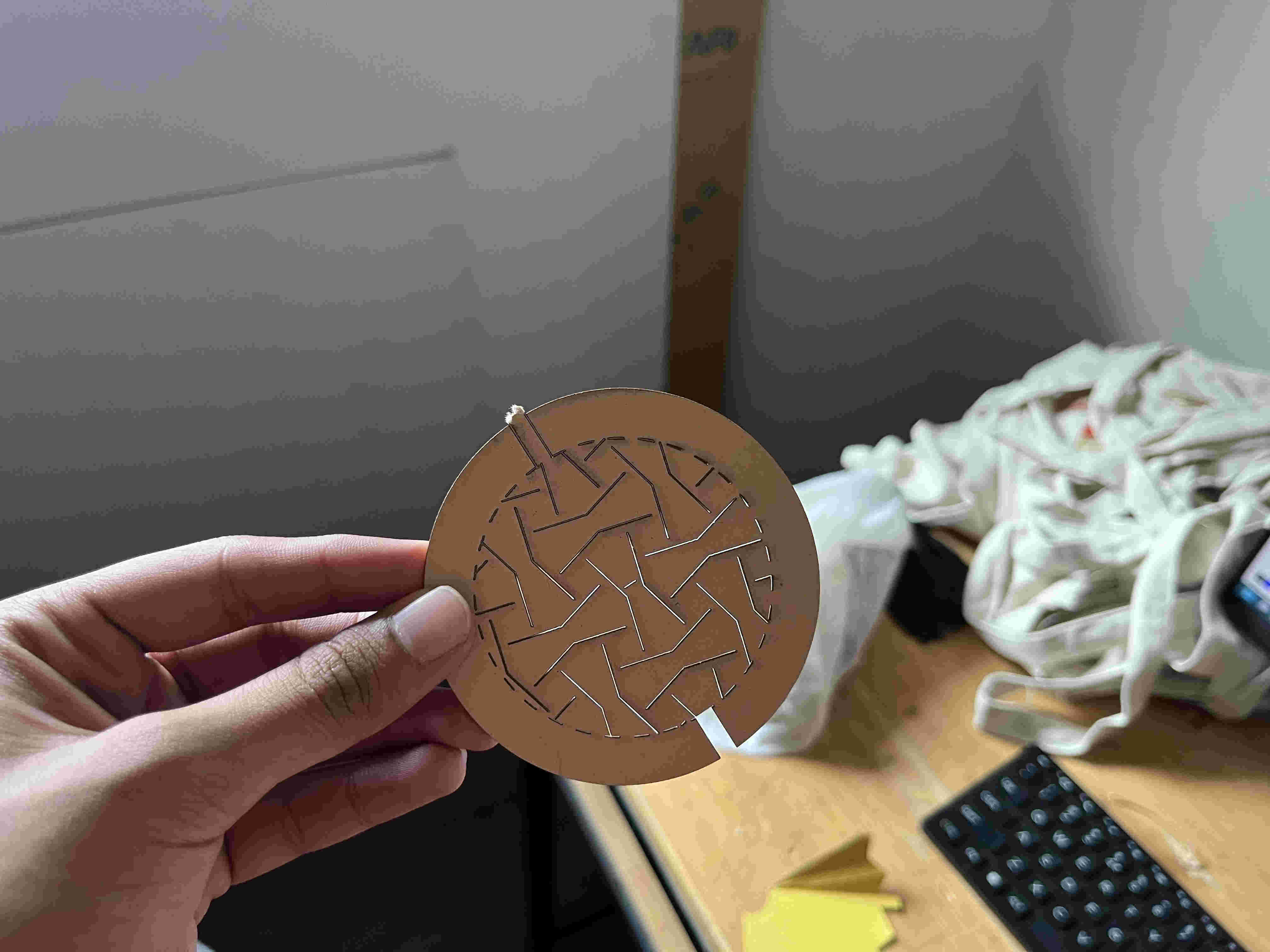
i imported the svg into fusion and made a circular bottom design and overlayed the svg on itIn rd_works i made the outer line dotted to give the shape some flexibility if neededLasercut cardboardThe result was not unaccpected.....
but not desired either🥲🥲🥲
Even though it tore off, you can clearly see it slighyt expandning on one spot. so the hinge itself works I just had to tweak it a litttle
I thought of trying new materials
Yellow cardstock paper - tore similarly
Too brittle
In the fab website- they had used rubber sheets, but I wanted to experminet similar cuts with different materialsFinally i thought I should try designing square auxetics myself maybe then i can fine tune it easily, I used chatGPT to do so
(╥﹏╥)Failed miserably(╥﹏╥)https://youtu.be/2tKj7wQtXxYTutorial to try out auxetics on rhino
.Auxetics on grasshopper.
(╥﹏╥)The add on is not on mac(╥﹏╥)Improvements in design that i can do
. slot angle increment in every layer using parametric
. trying out the model on software
. Exploring machines.
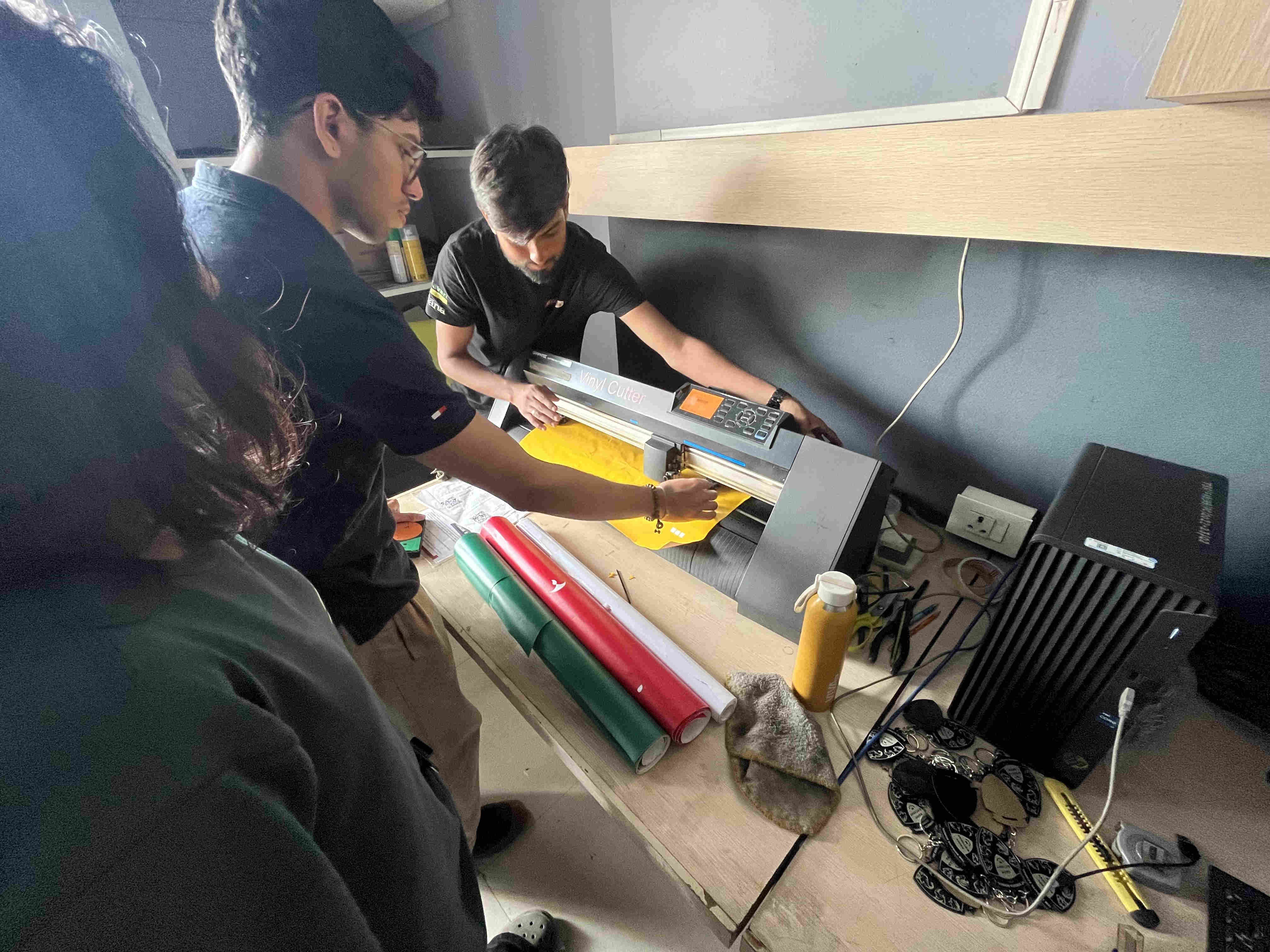
.VINYL CUTTER.
Trying out Graphtec vinyl cutter
We used matte waste vinyl sheets with an angled blade to try out stuff
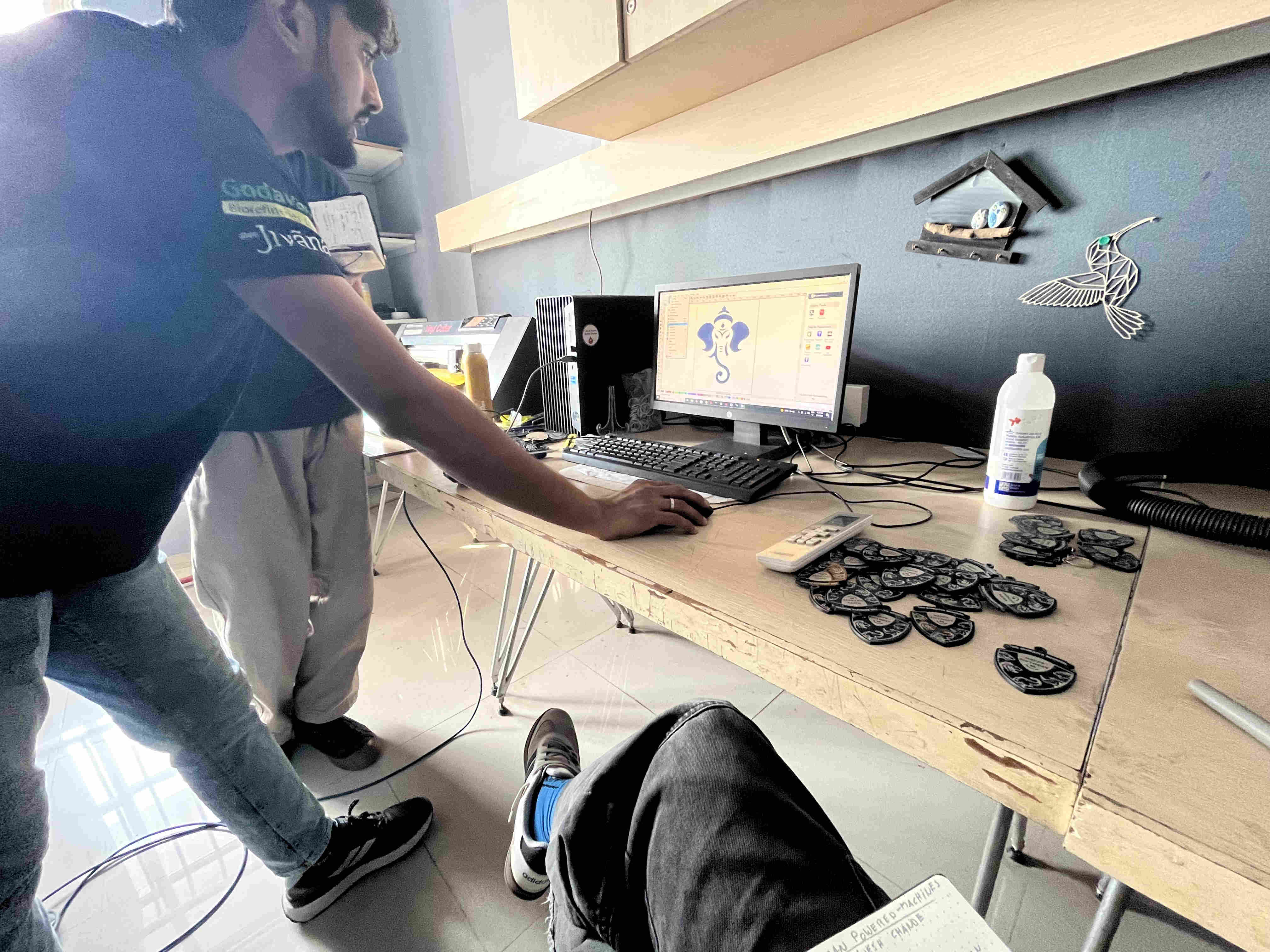
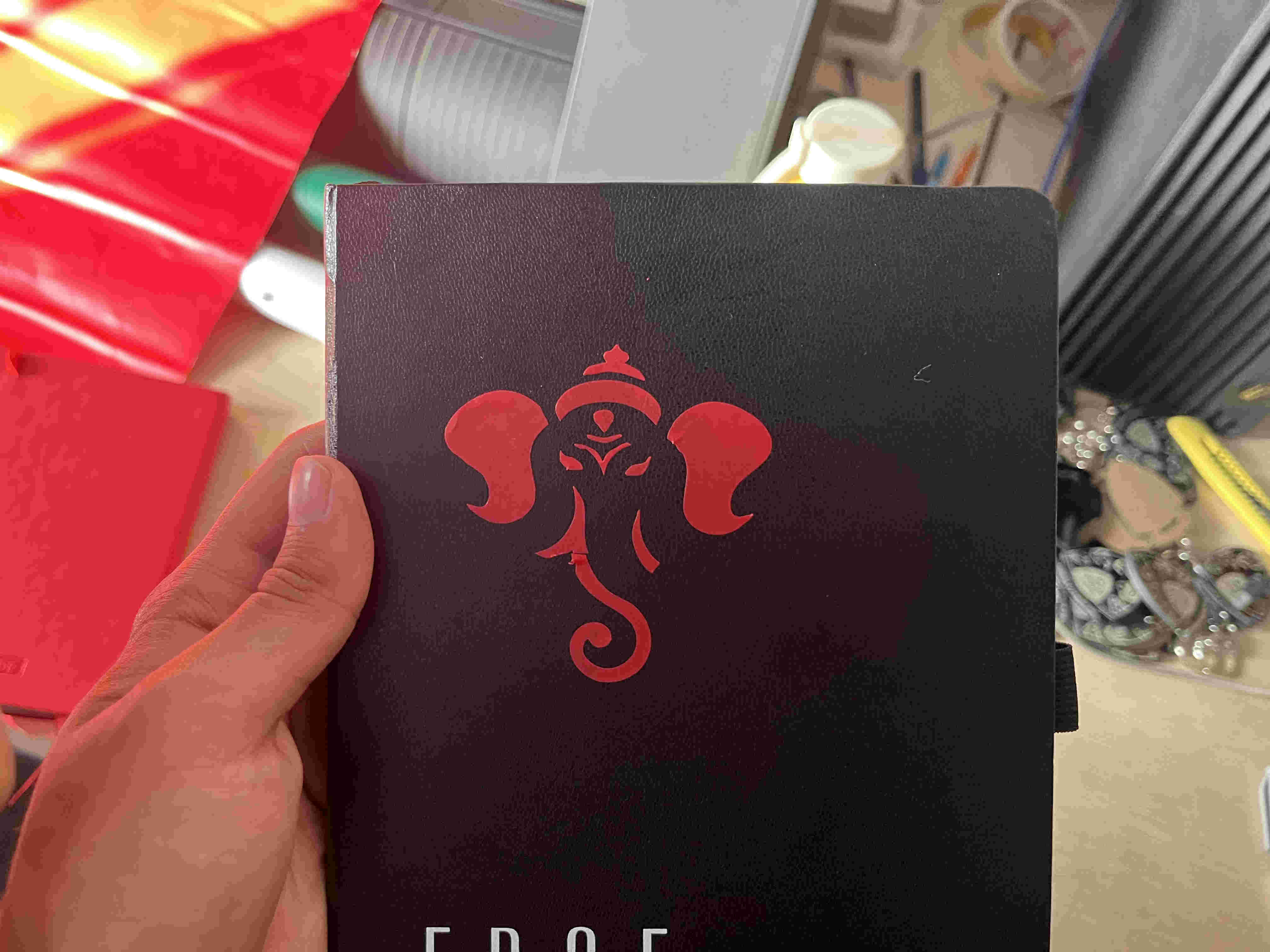
We first took an existing raster image of ganehsa, traced it using graphtec autotrac command and send it to the cutter
Software used- GraphtecOnce cut we picked it using a tweezer manually, (trnsfer tape had lost some of its adhesiveness)
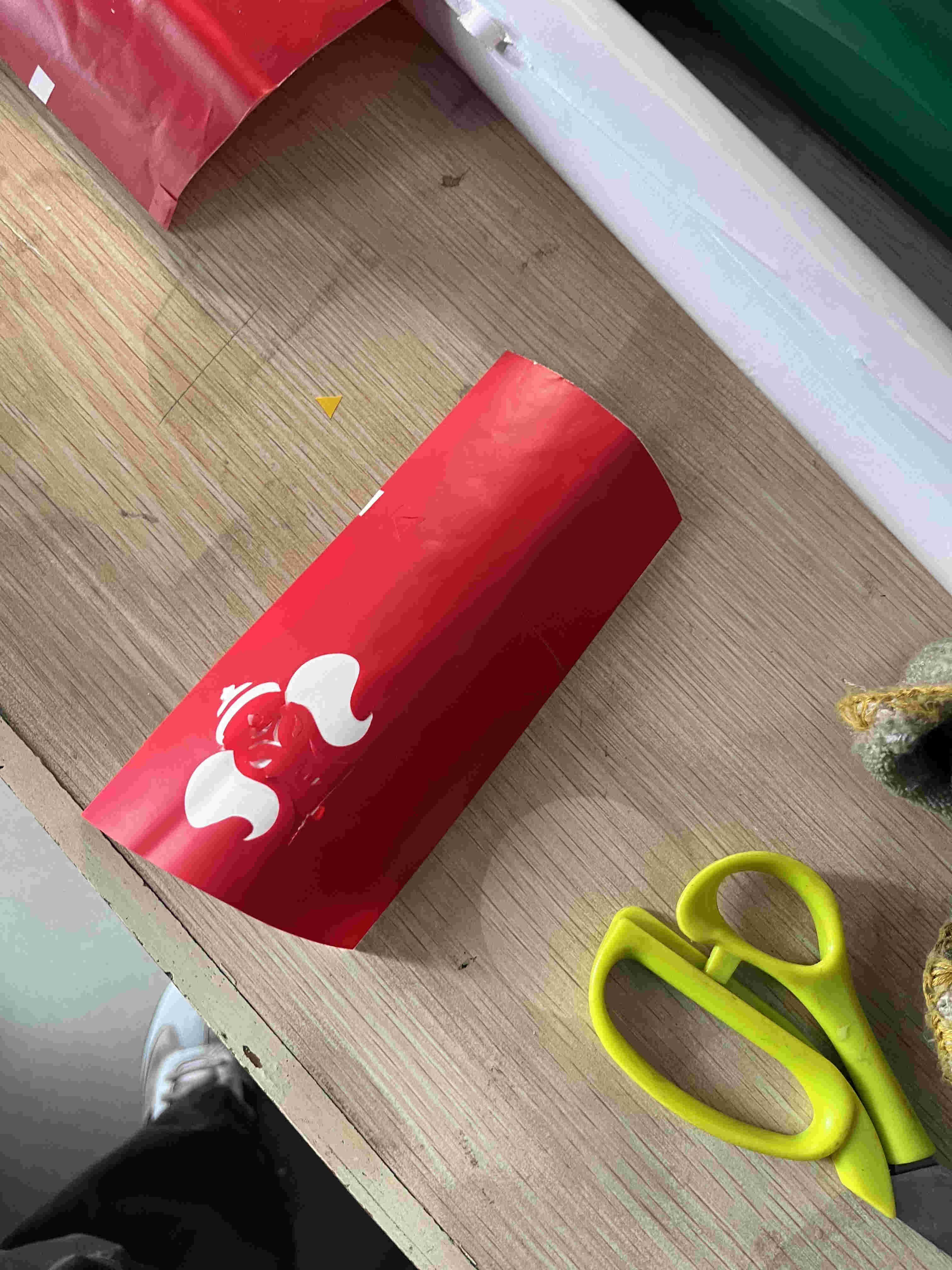
Final result.
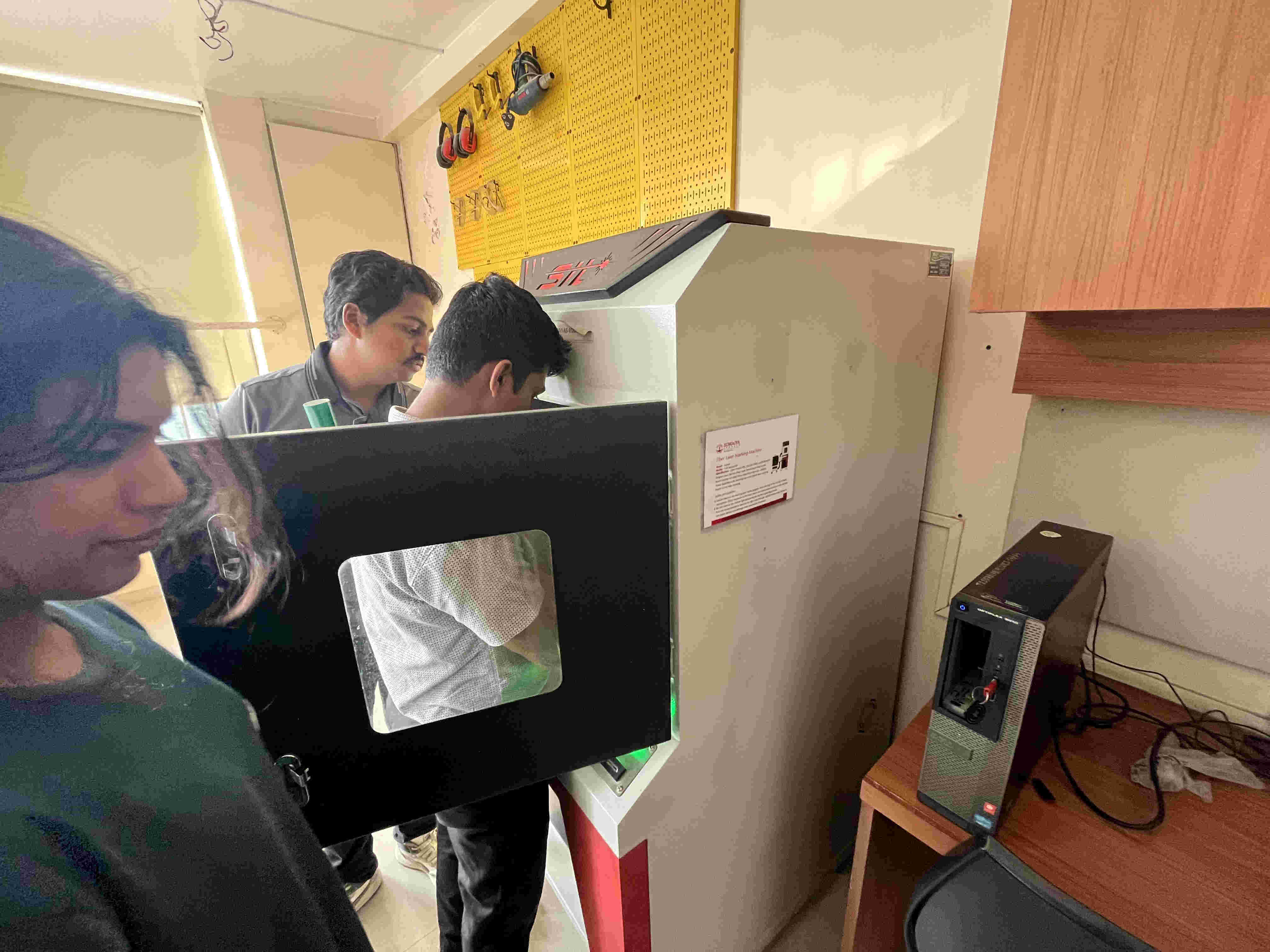
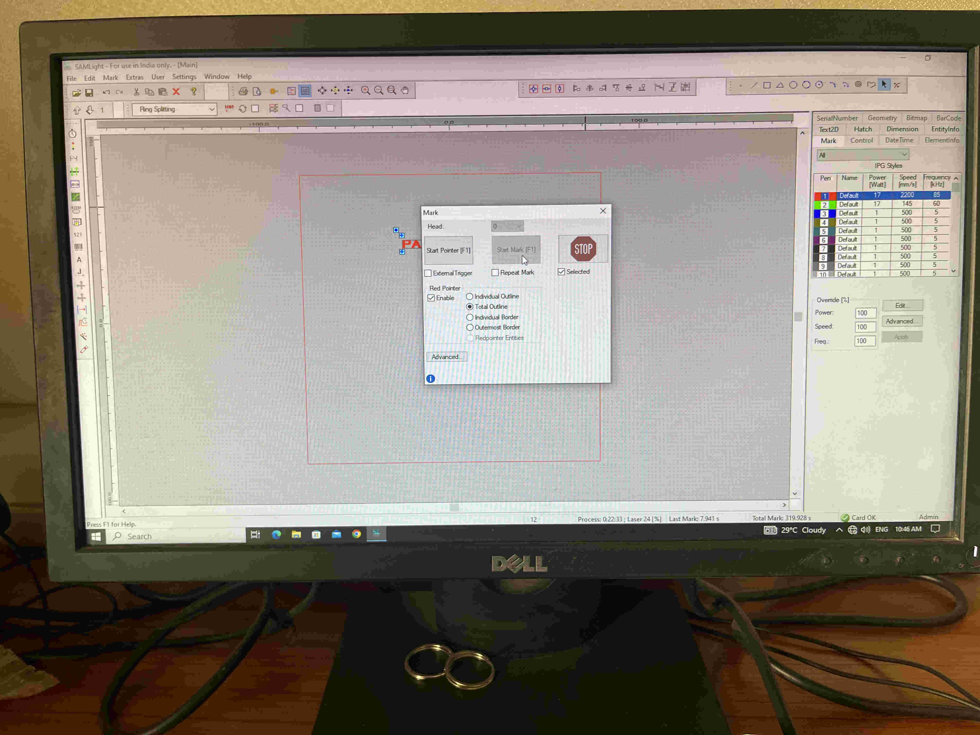
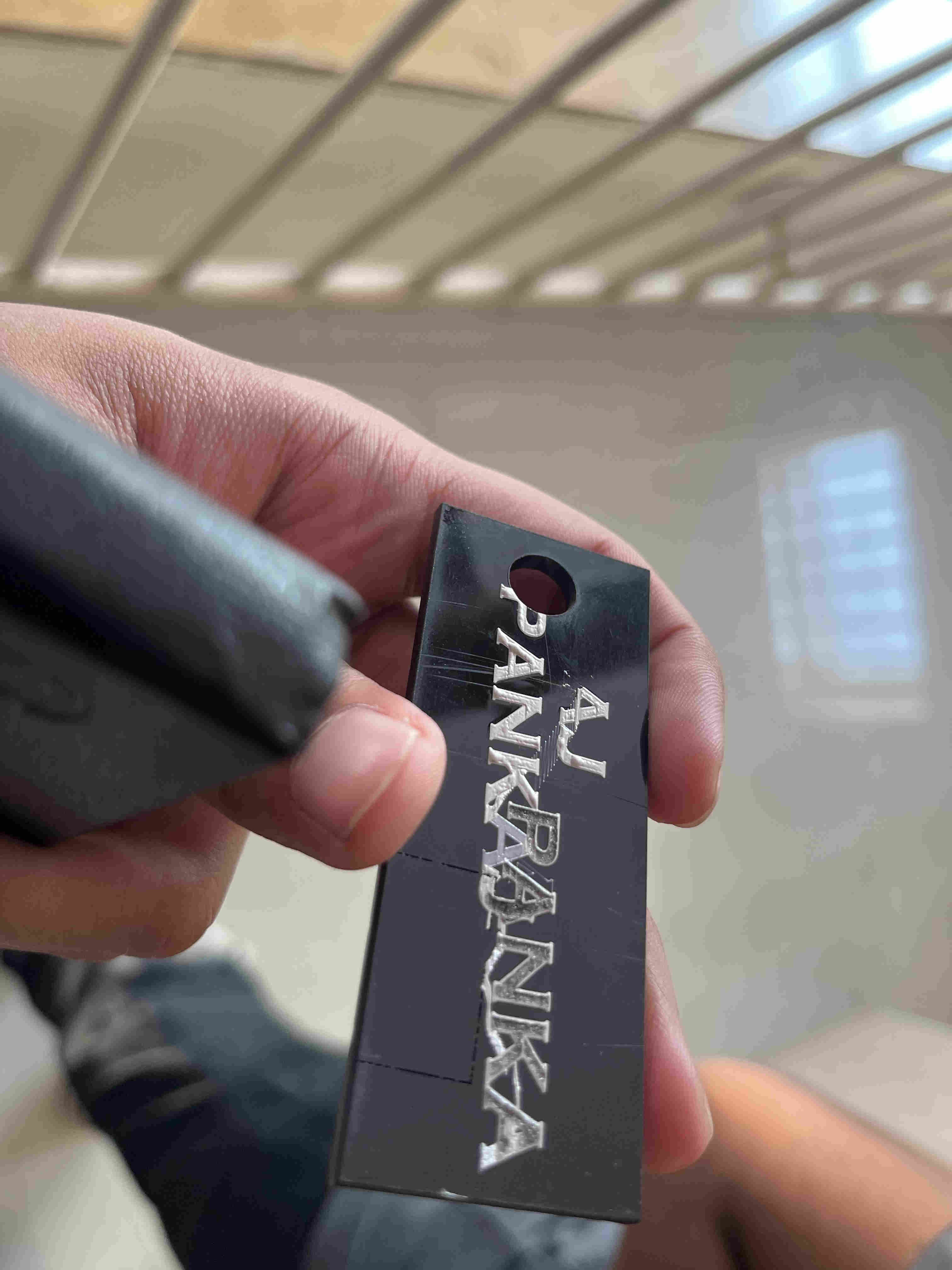
.FIBRE LASER
A fibre laser is very interesting, with the corrcect speed power and frequency, you cna use it to emboss an 'engraving' onto plastic
sounds wierd right.
Fibre laser
software used- SAM lightMultiple trials of speed and power for optimal and best outcome
material - 3mm acryllic
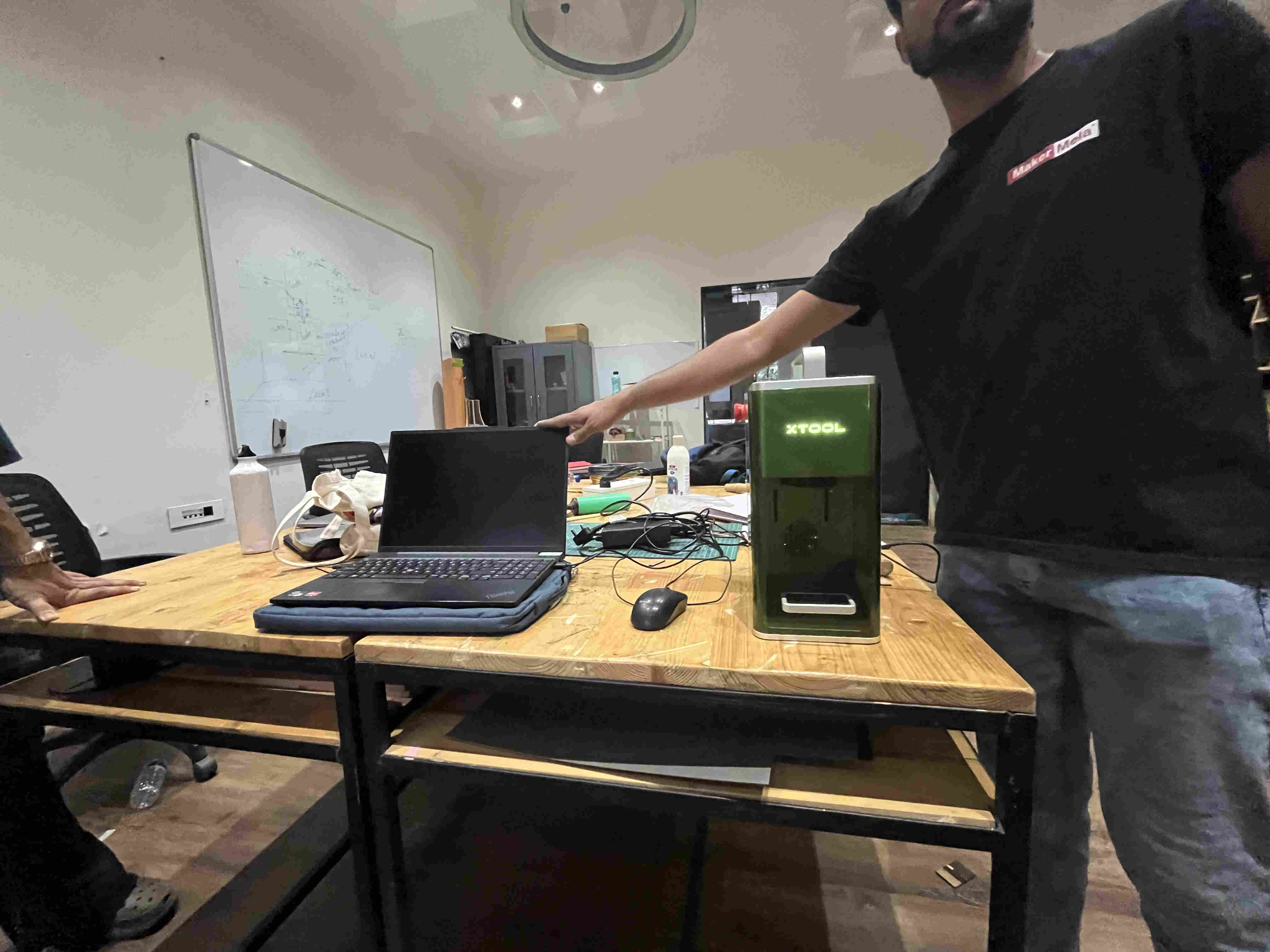
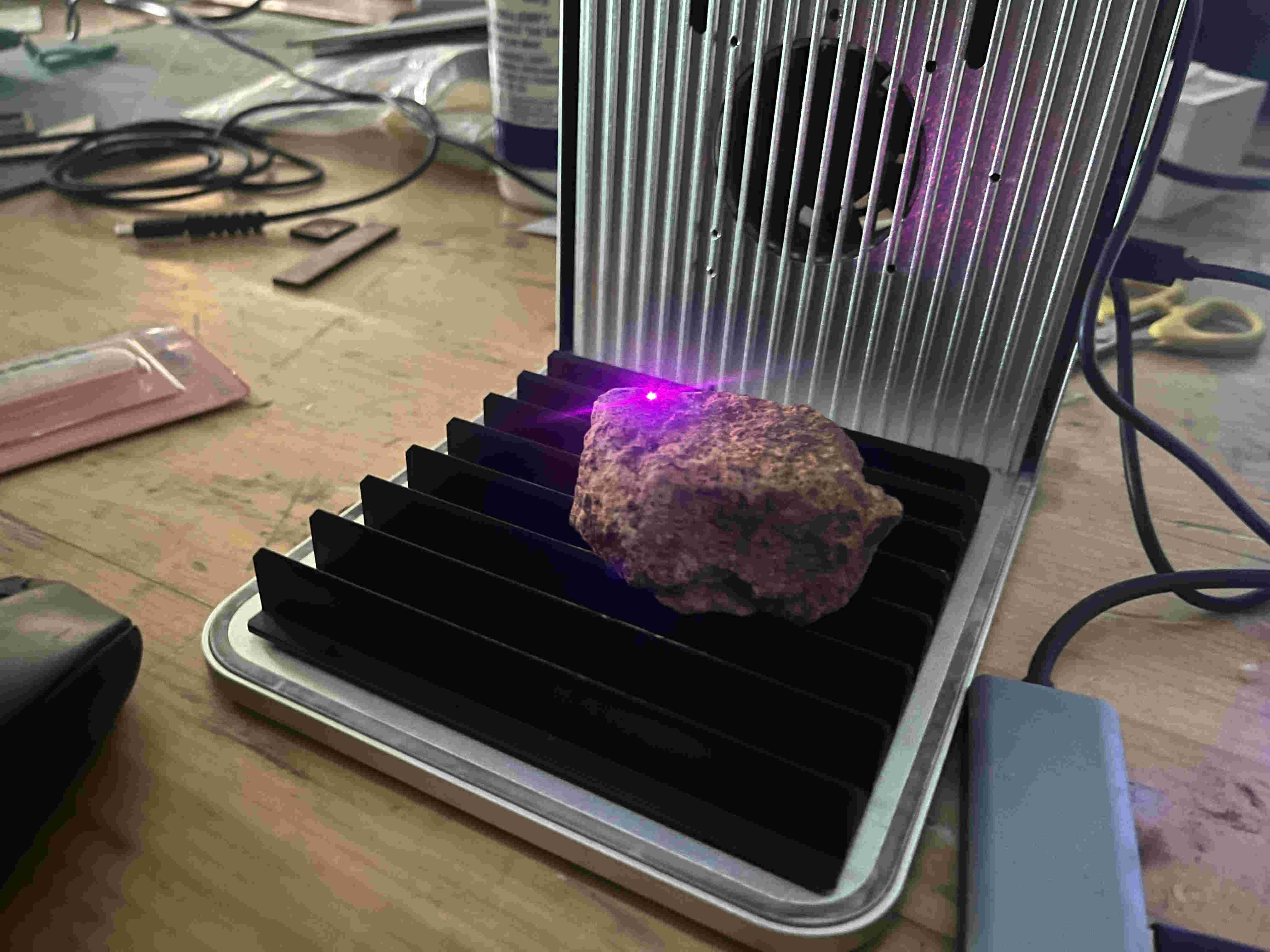
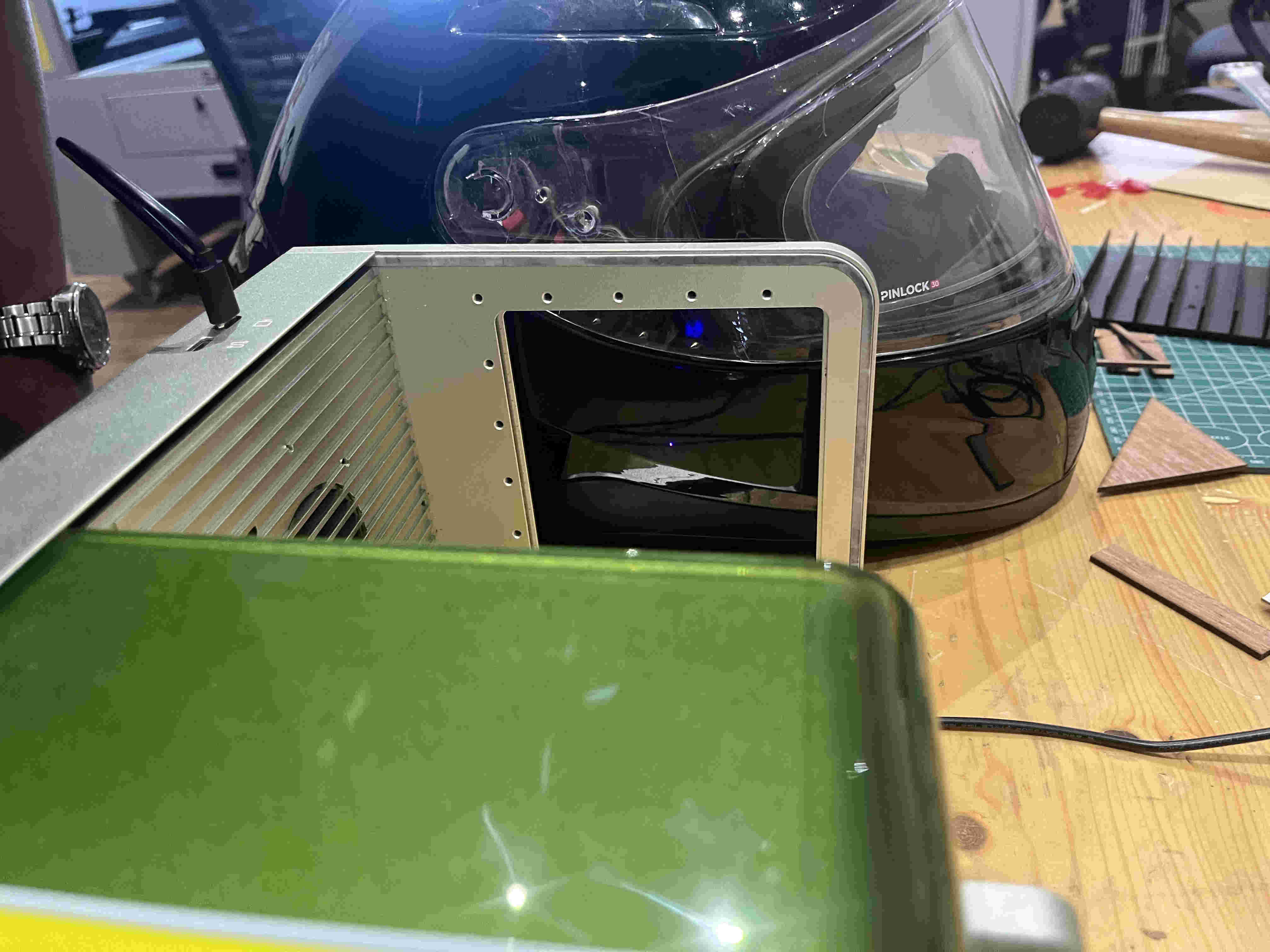
.XTOOL.
Xtool is very intersting, It works very similar to the fibre laser but is extremly intuitive AND PORTABLE!!!!!!!!Not just portable in sense of movement but in sense that it can engrave on any surface, you can carry the machine and place it on walls and any surface.
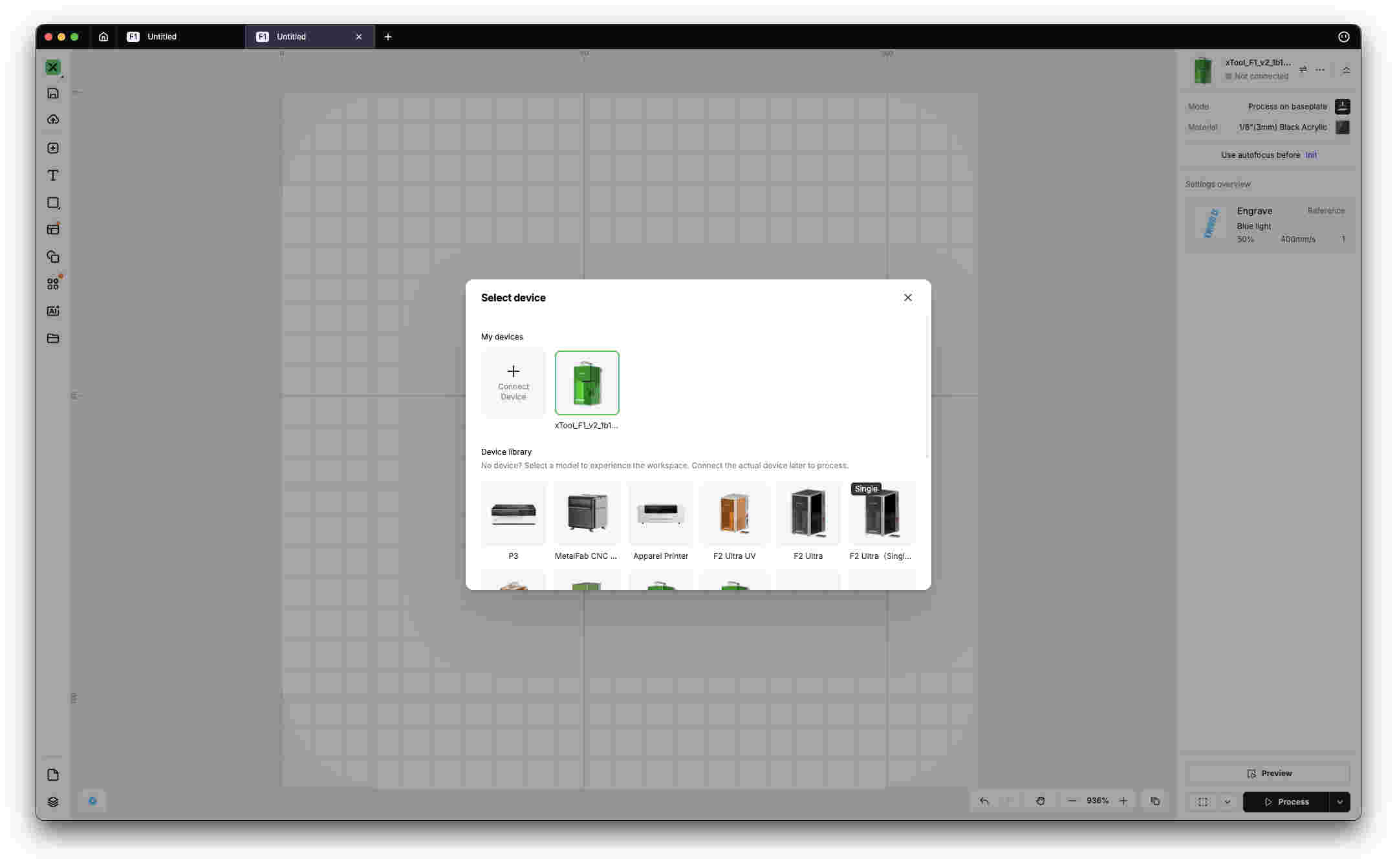
First you need to plug in your your laptop to the x took using the provided cable. tutorial to setup-
https://youtu.be/2SaGcA6qHFosoftware used- xTool studio
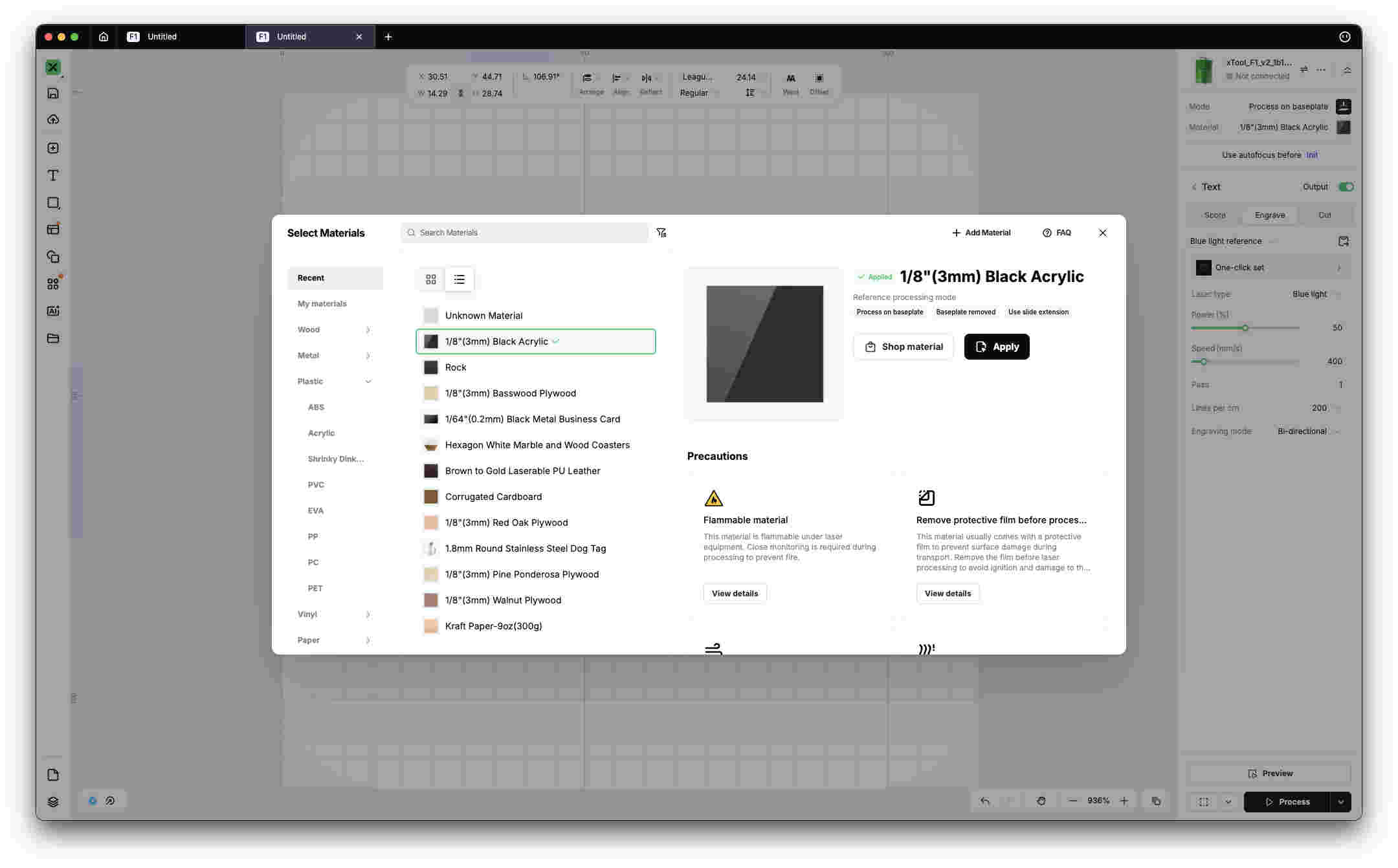
One excellent feature that xtool studio provides is material selection presets, power speed and focus will automaticlaly be adjusted by selecting desired material.
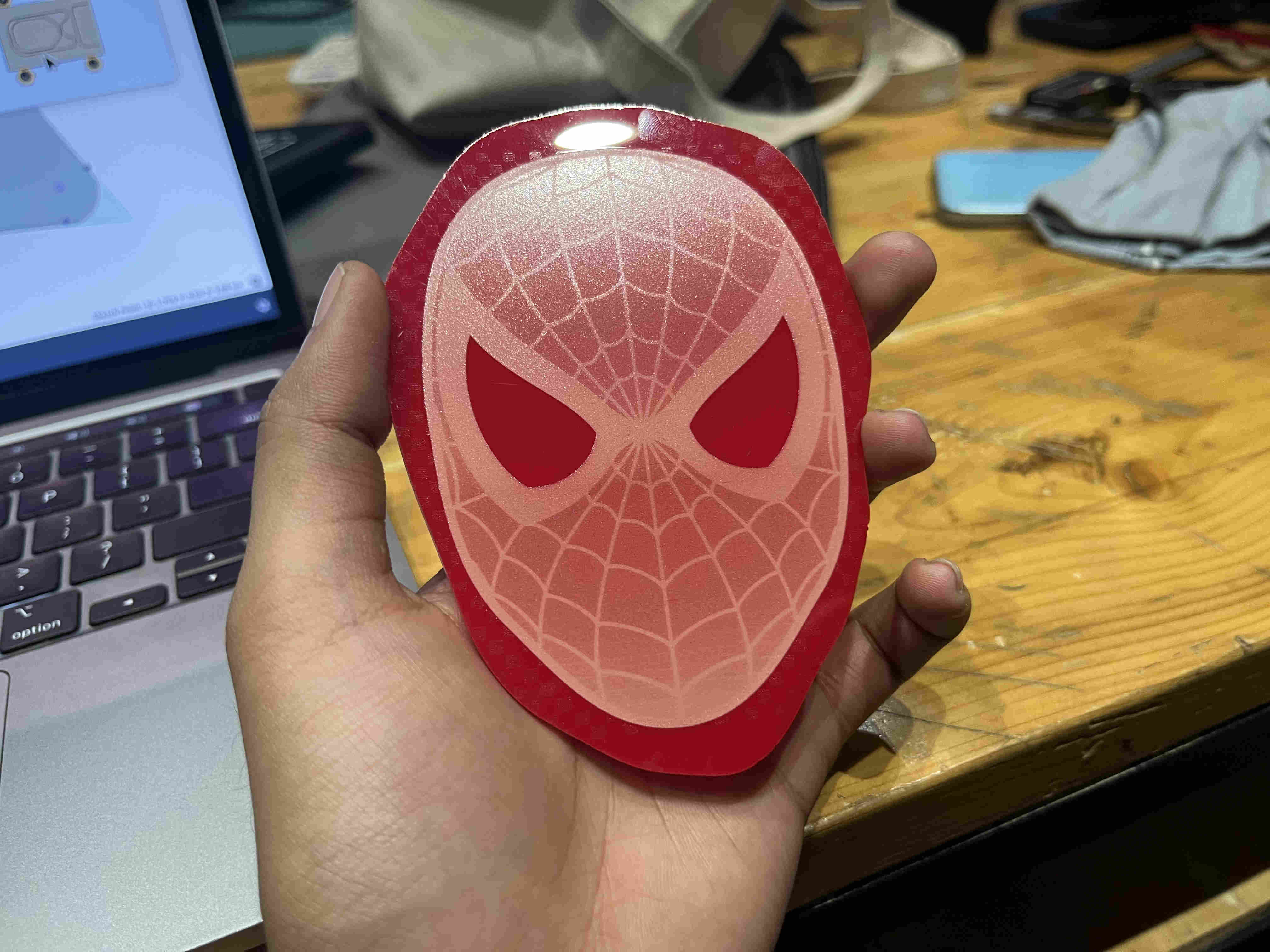
First trial on a waste acryllic- (Tribute to Ms. miriam)
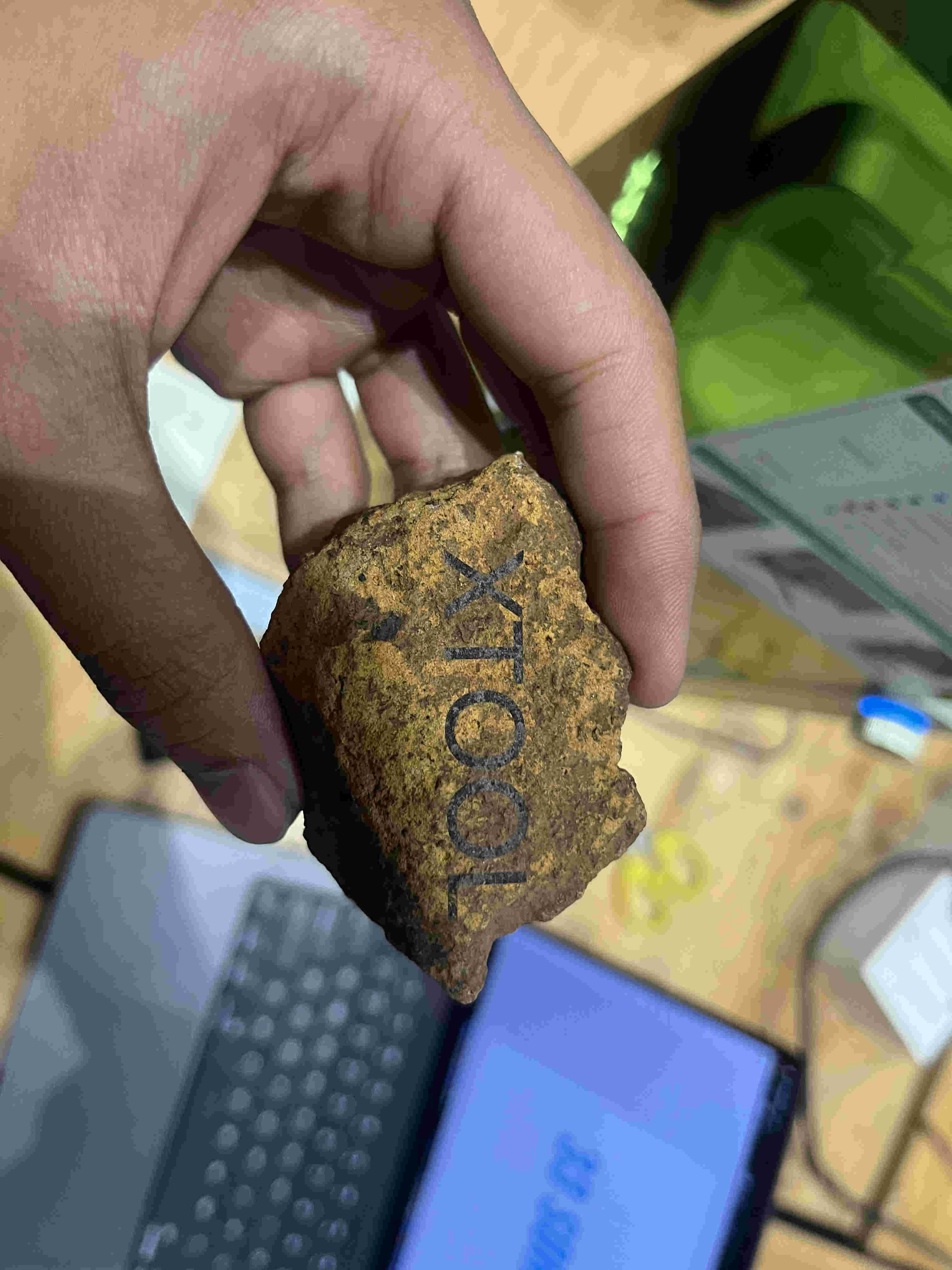
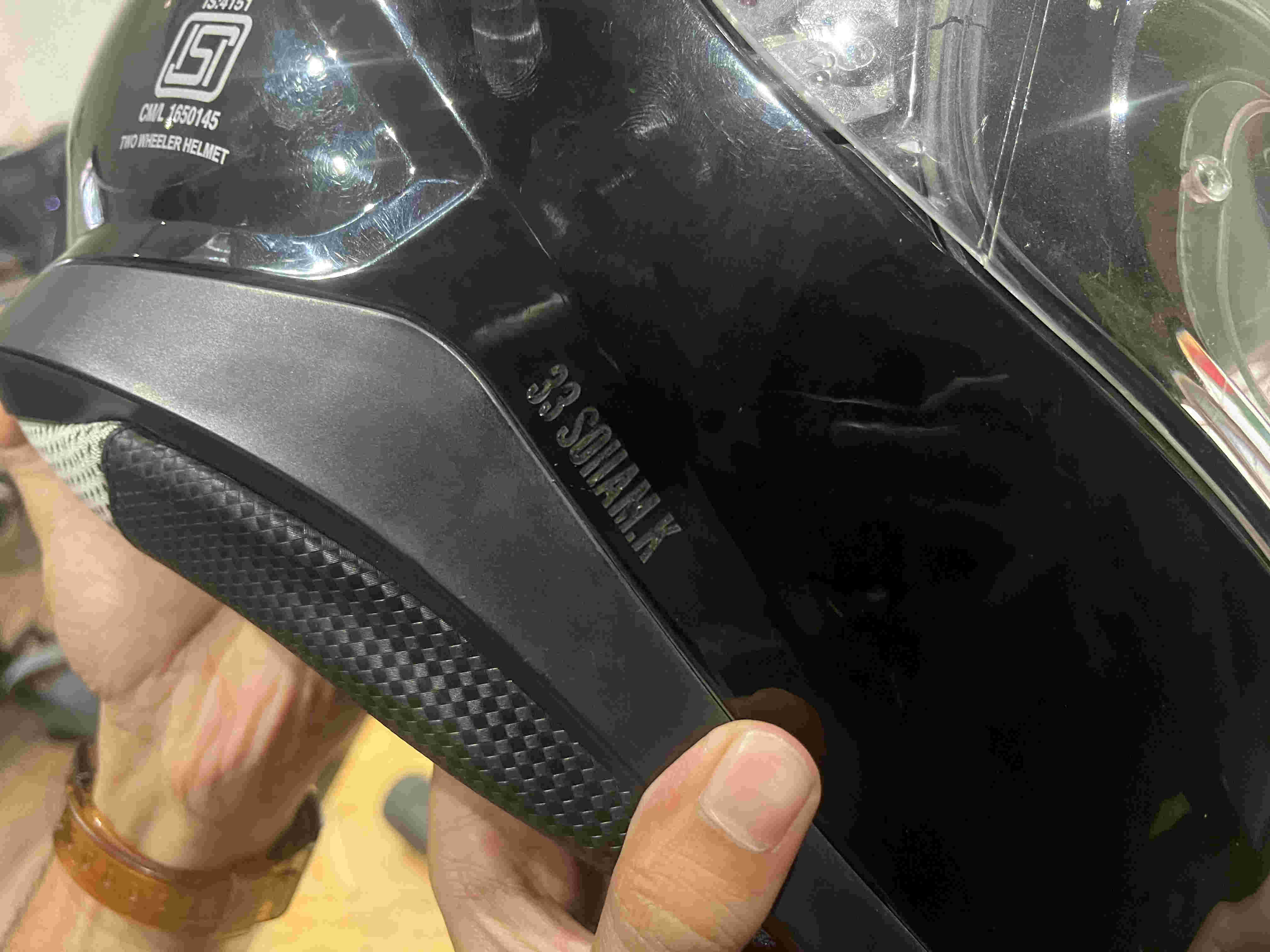
It can even engrave stone??!!.
result.
Everything gets engraved😈😈😈😈😈
result
while using one needs to make sure the red light and the blue light merge on the surface to create accurate cuts. Using the knob on the side you can bring the head up or down.


