This week we come back to the lab, for a wierd requirment
Make somethingBIG
.Group assignment.
Understanding the machine
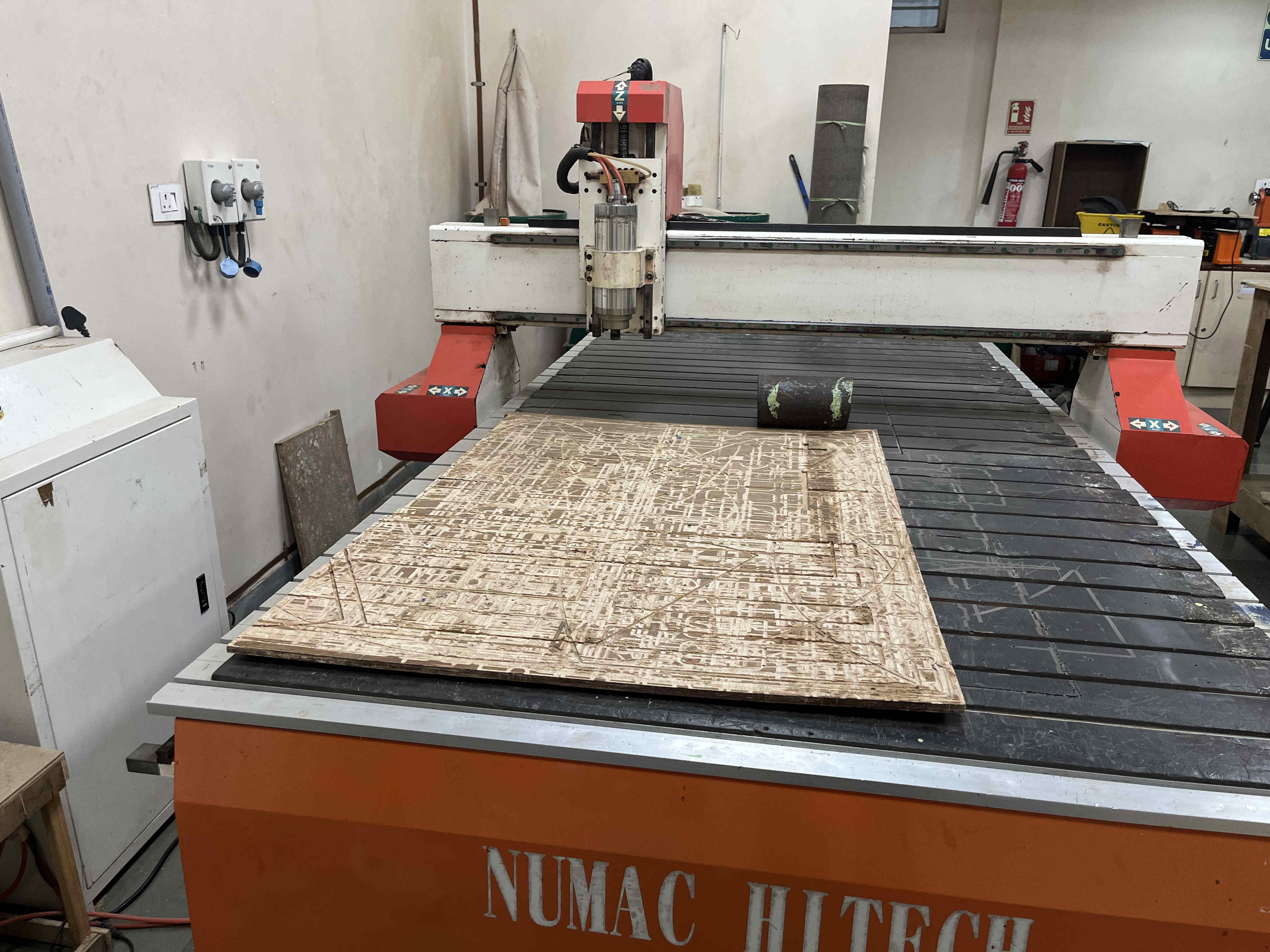
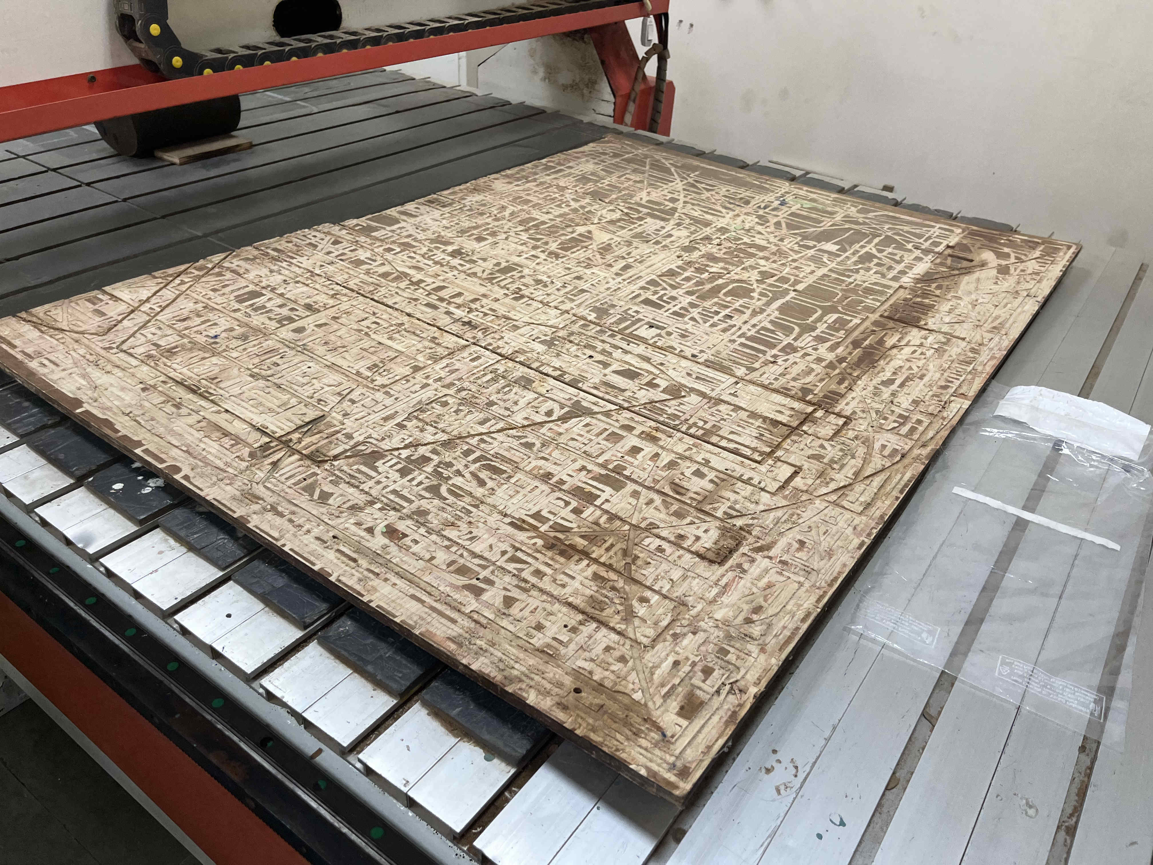
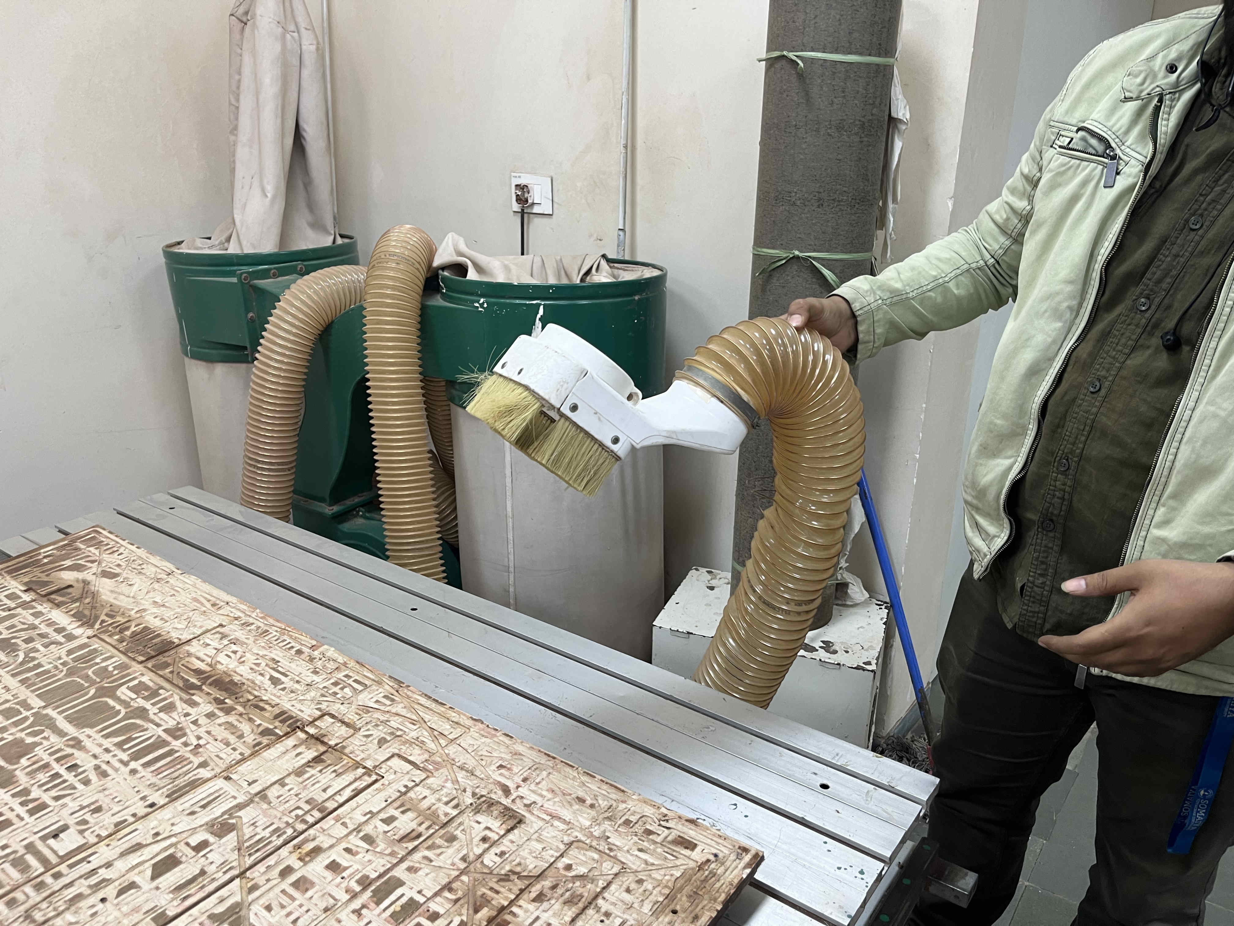
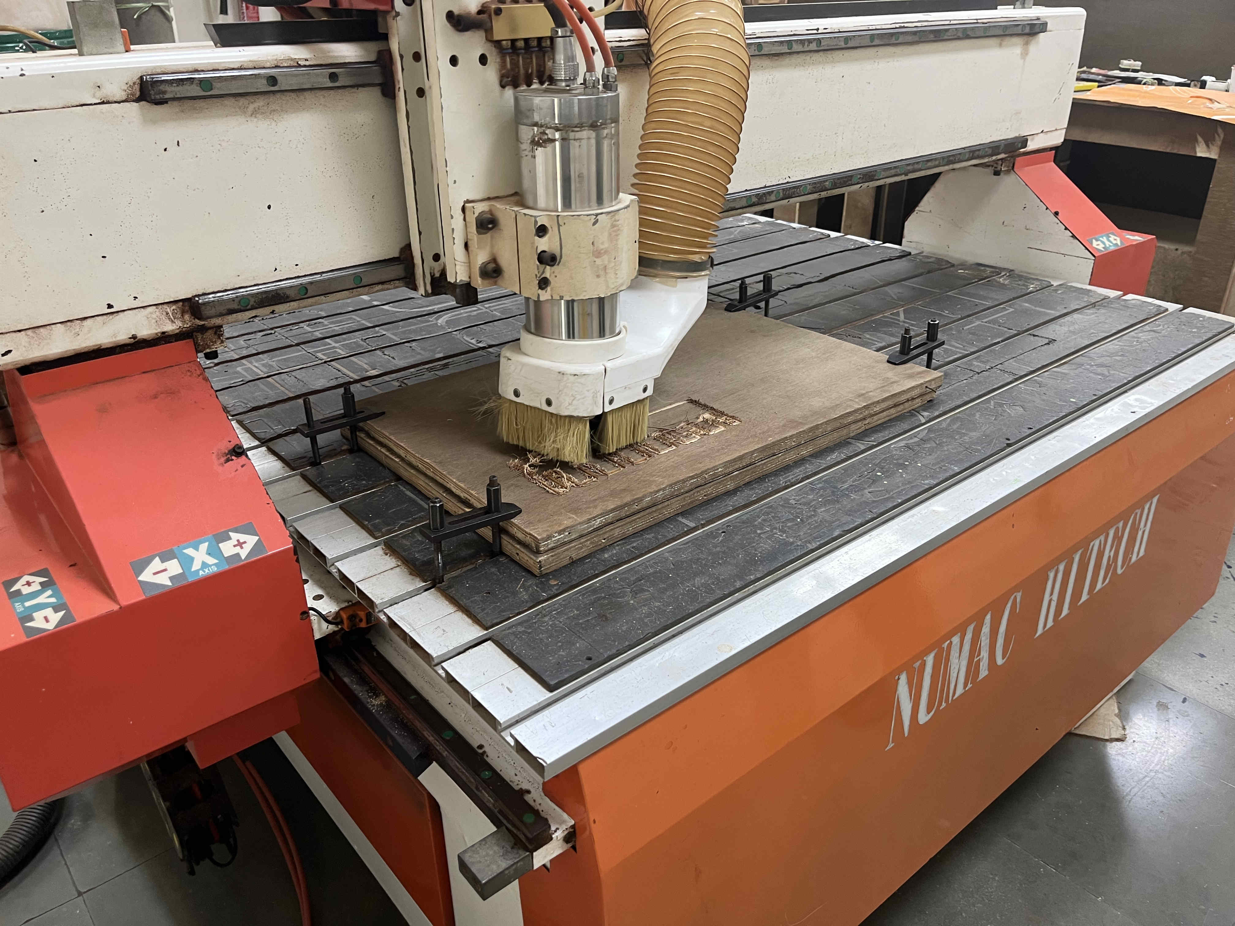
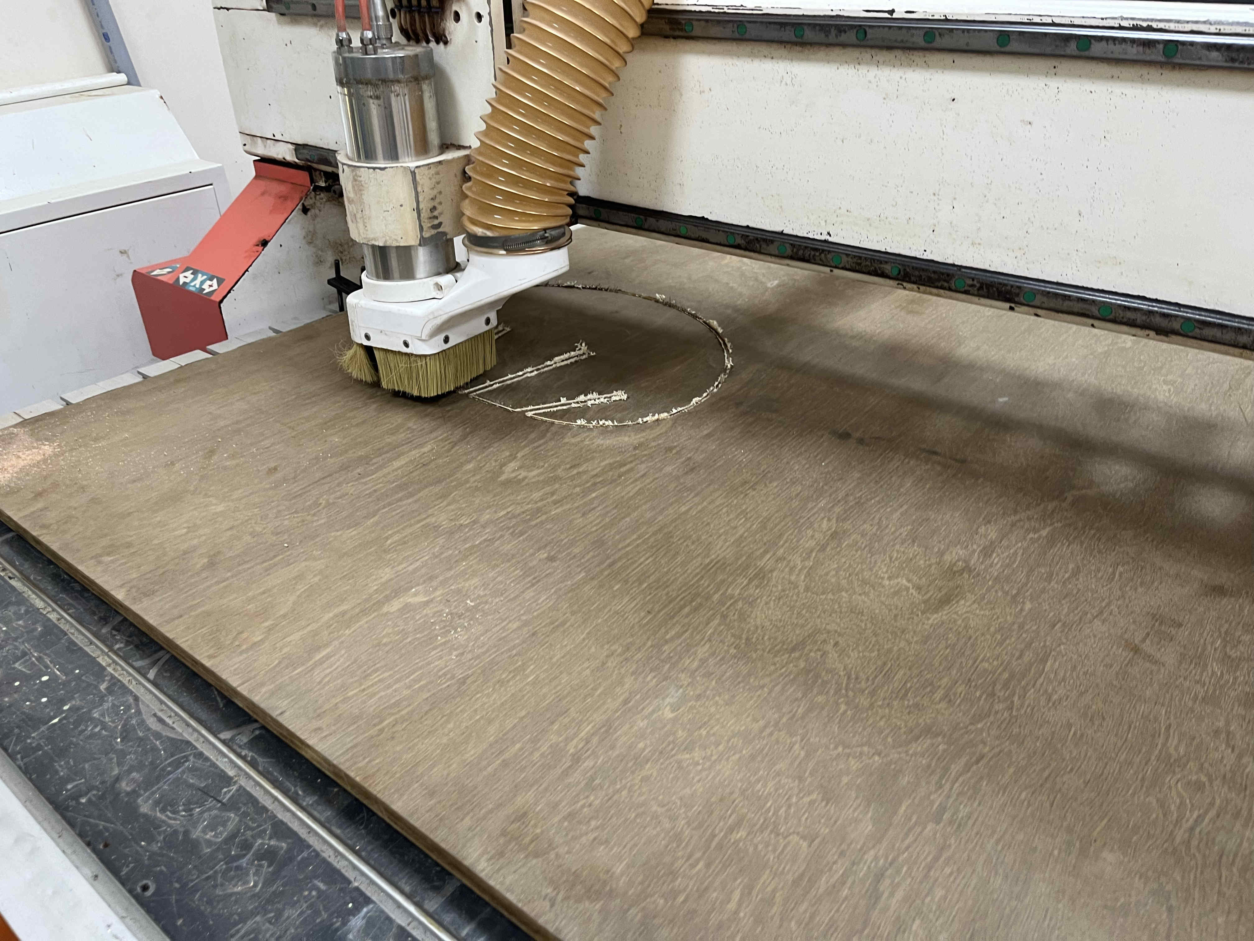
The machine we are using in our RIIDL fablab is a numac hi-tech 250The piece seen here is a sacrificial ply piece
This is needed becasue sometimes the Z distance the machine goes down to can exceed your wooden block, thus not having a sacrificial piece can damage the bed of the CNC machine
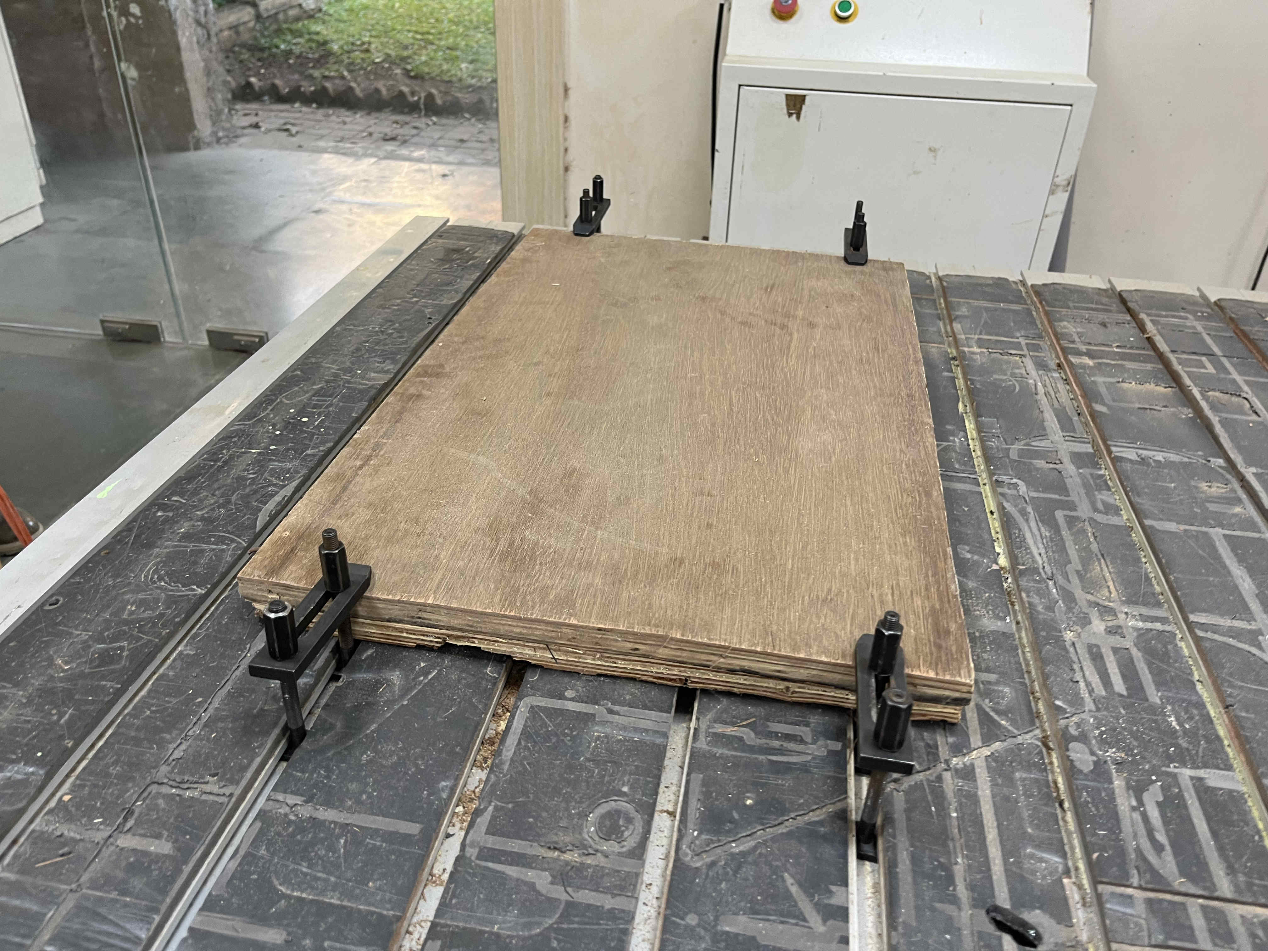
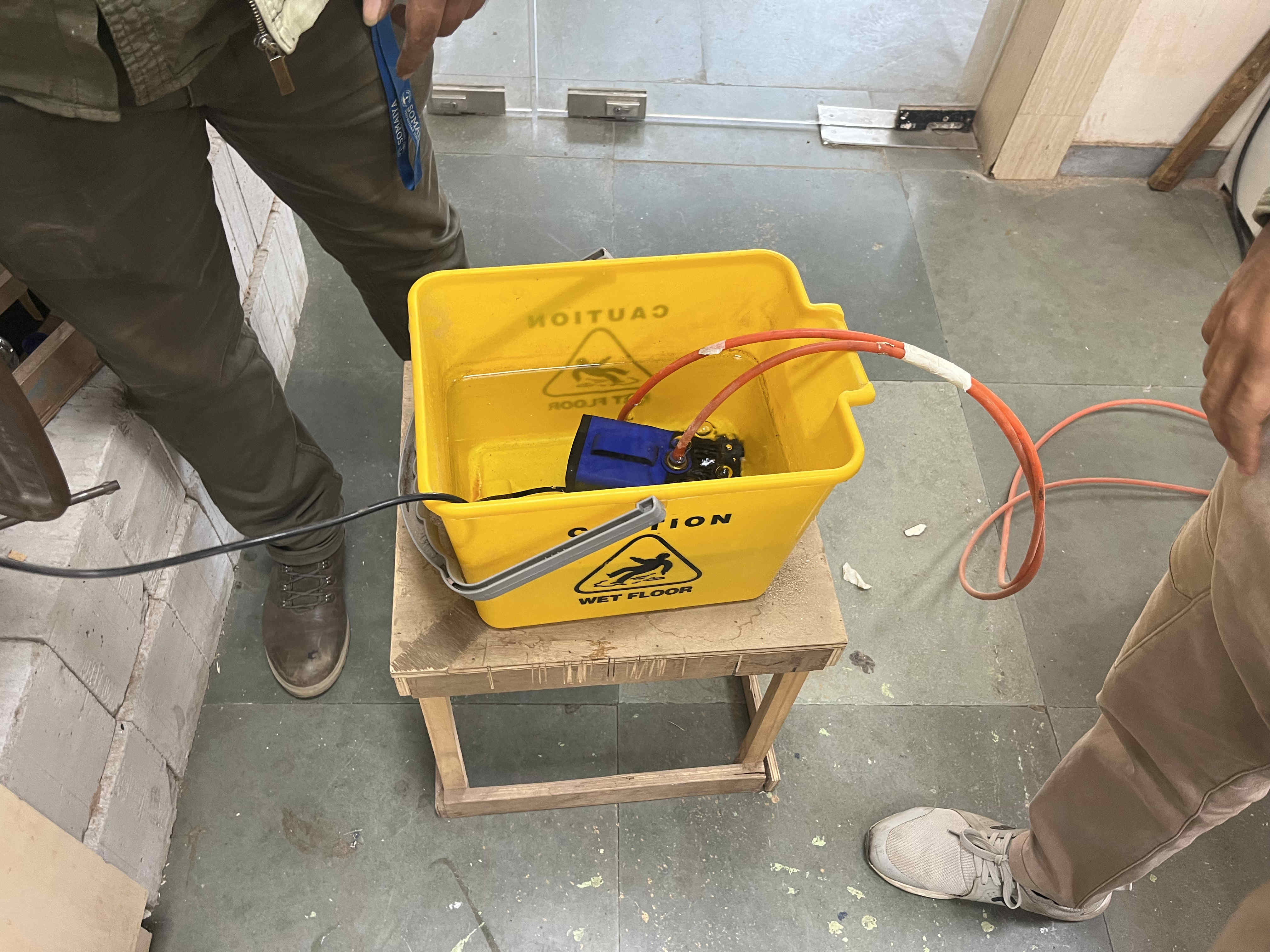
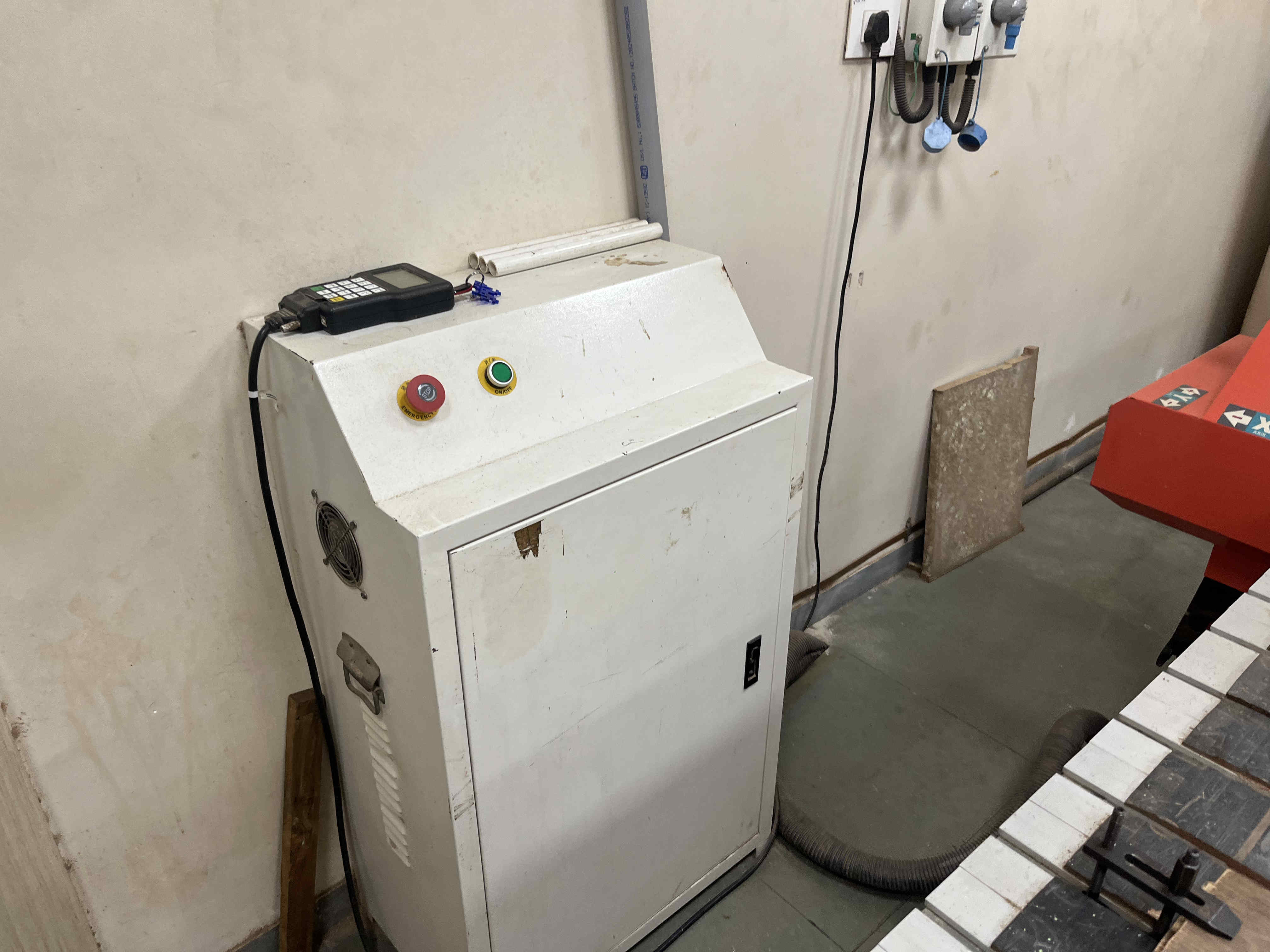
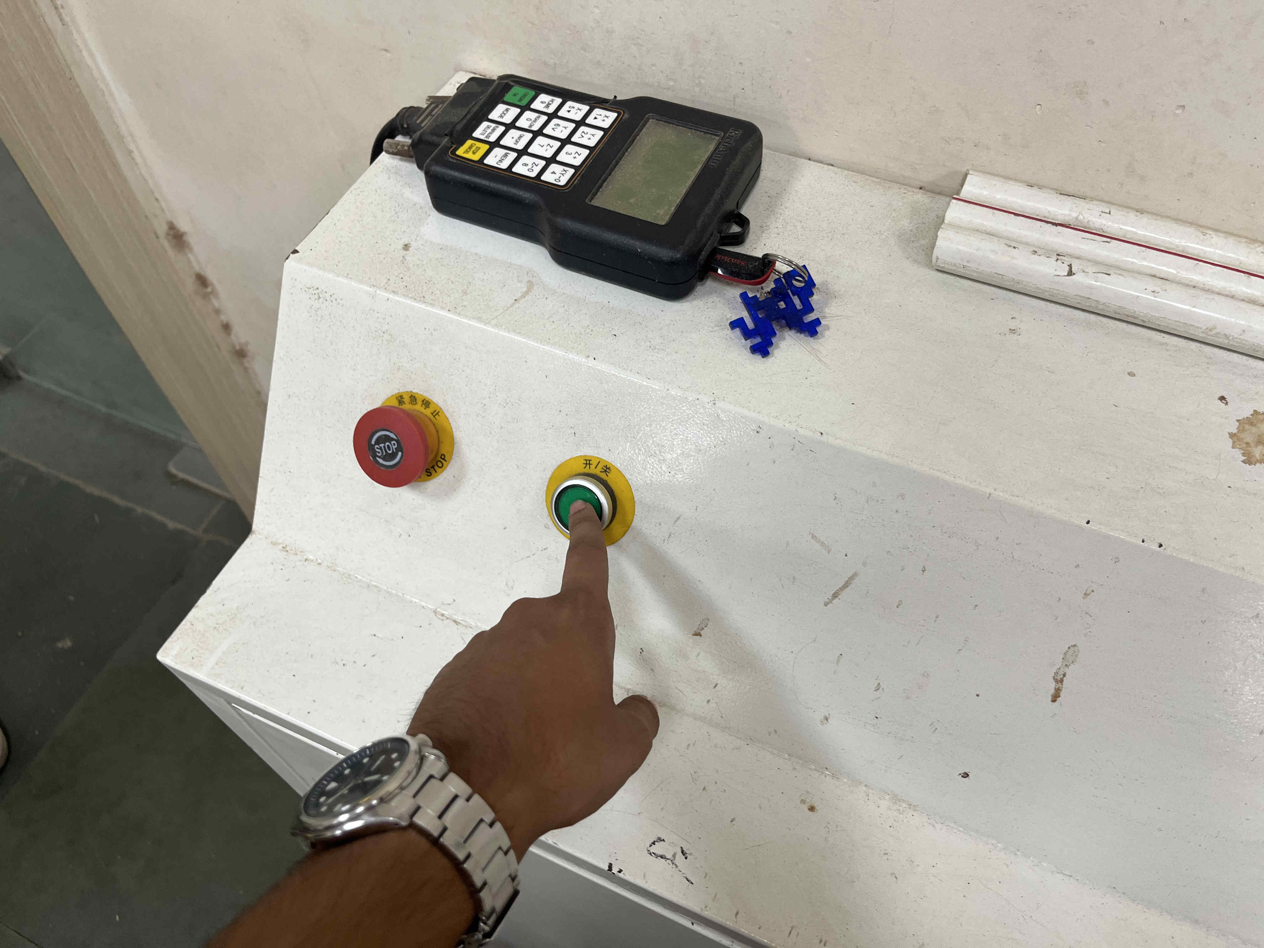
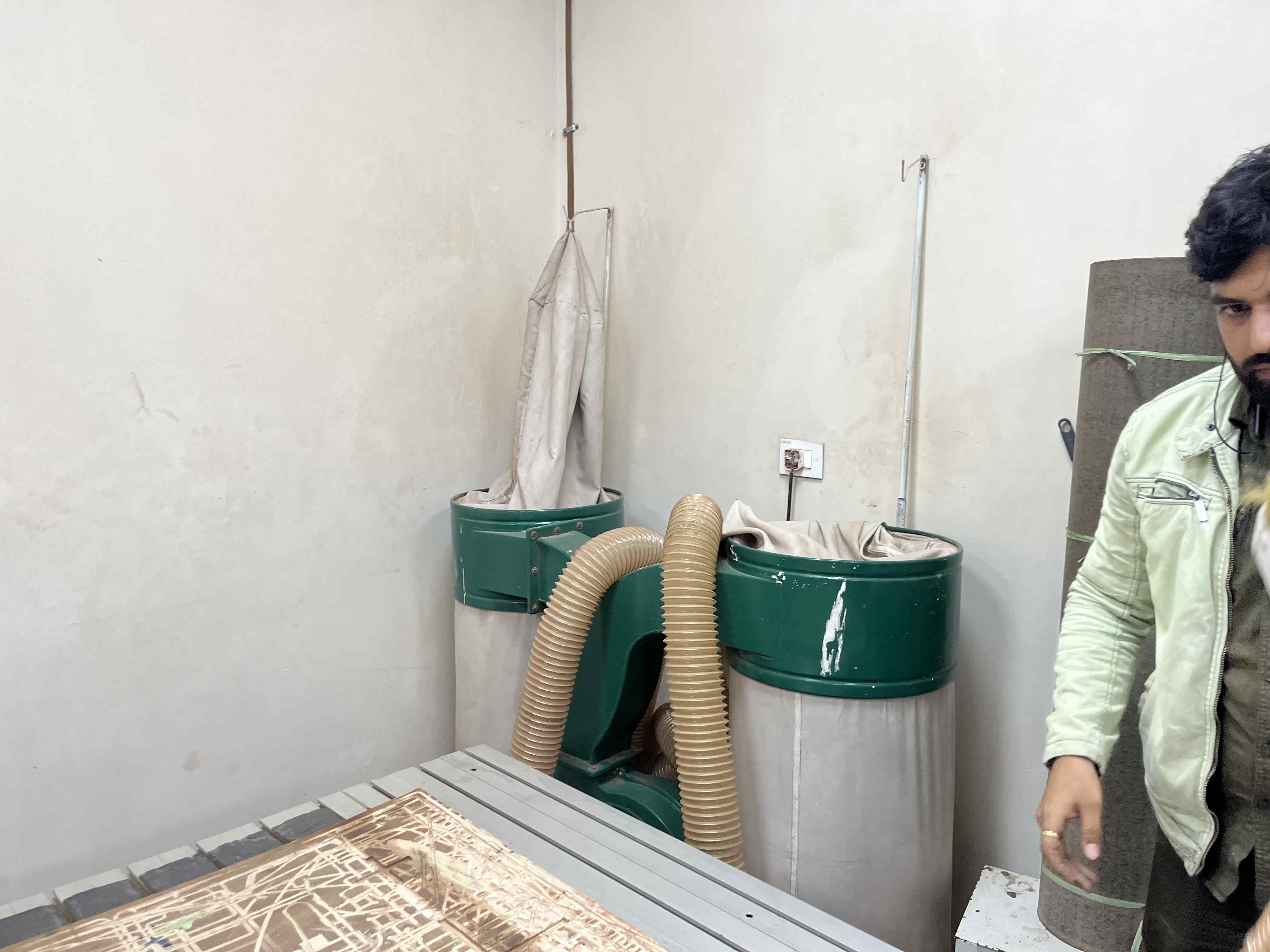
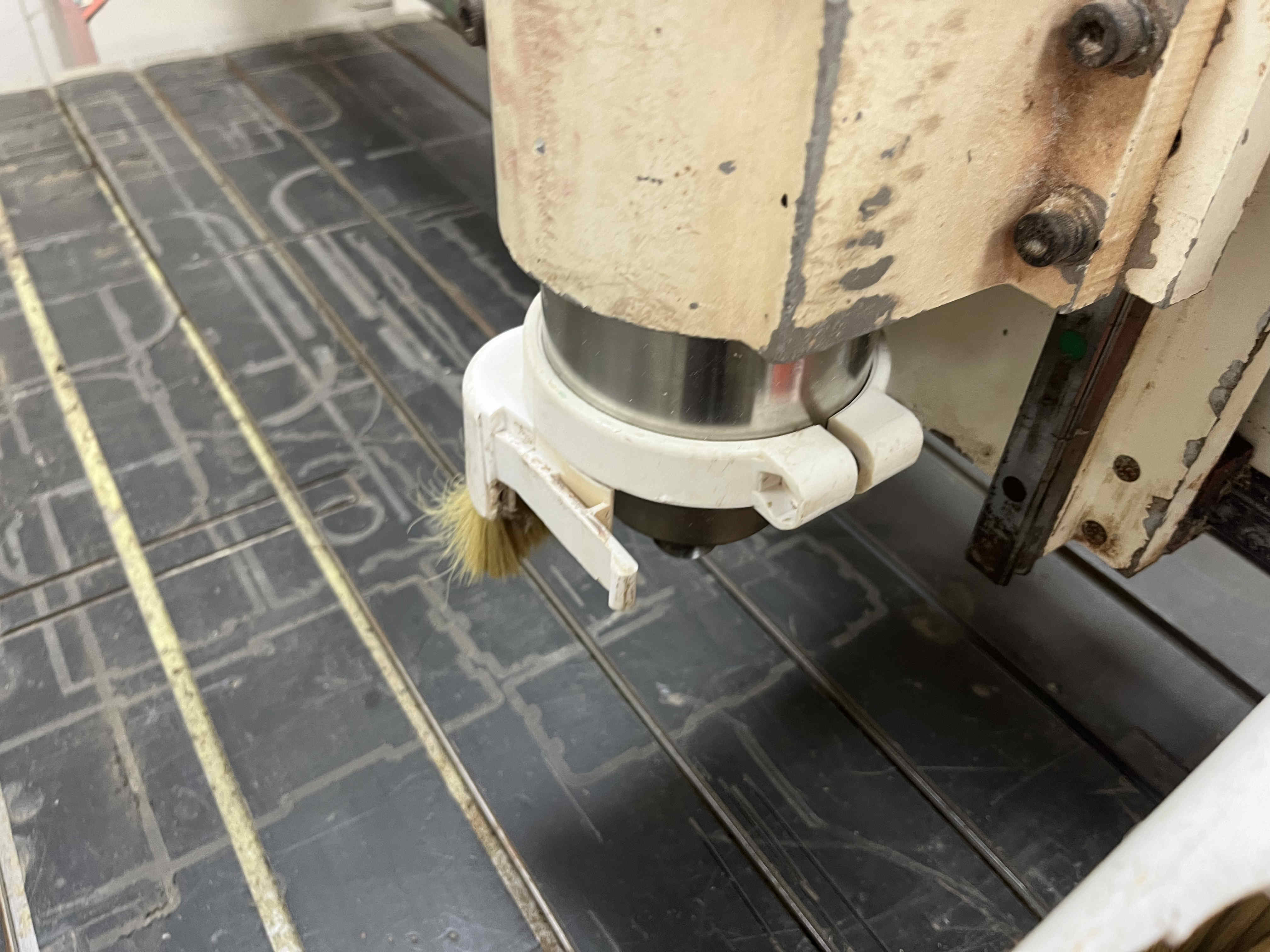
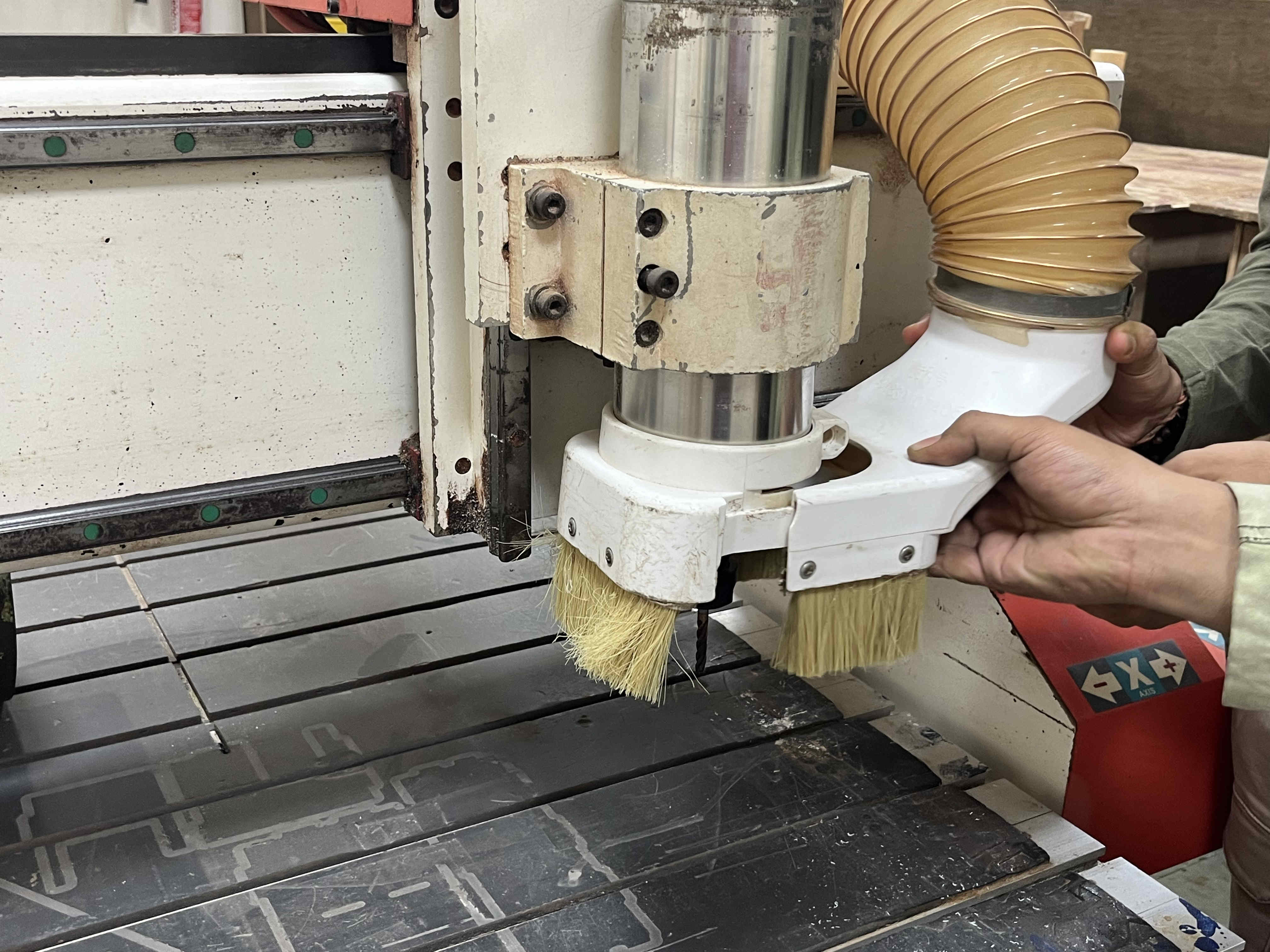
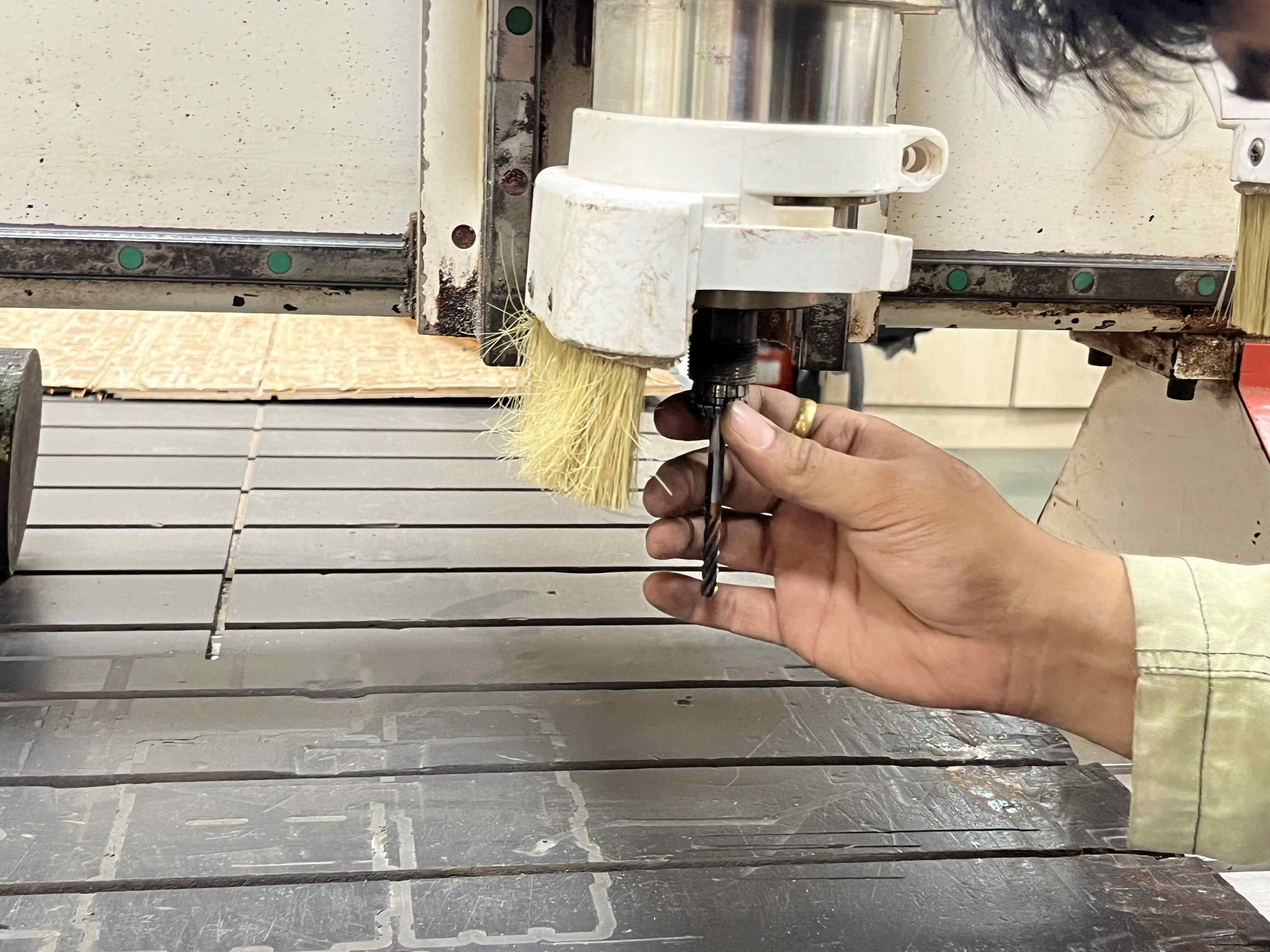
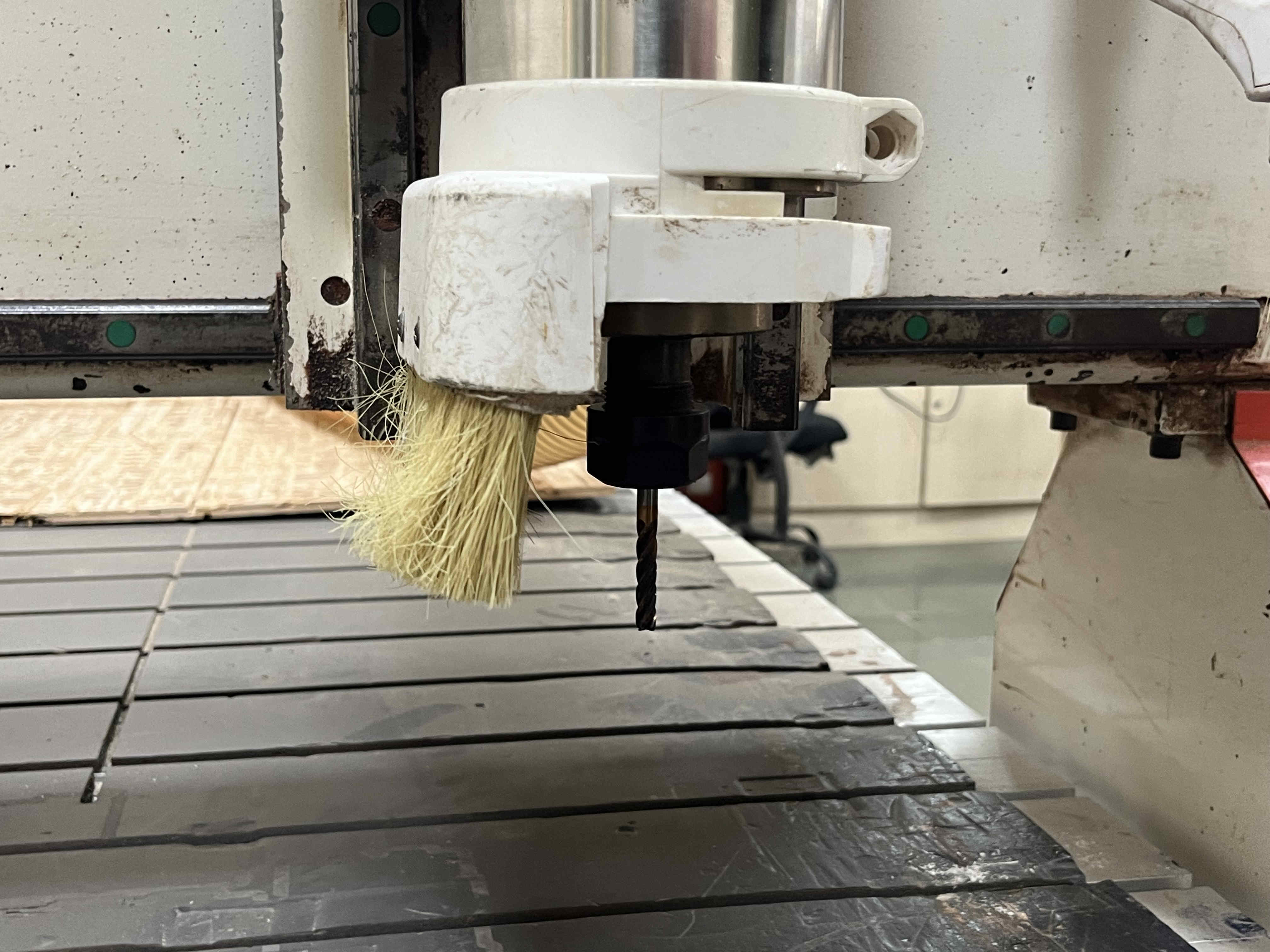
A piece can be clamped as such in these rails The spindle coolant motor is plugged in with a feed and recive tube in the tubeController for the machineOn and emergency stop buttons are placed as suchController remote to feed files and control spindle head, feed rate on the go and moreVaccum system Vaccum head to be attatched on the spindle One half of the spindle attatches as soSecond half of vaccum head can be attatched once the collet and drill is fixed
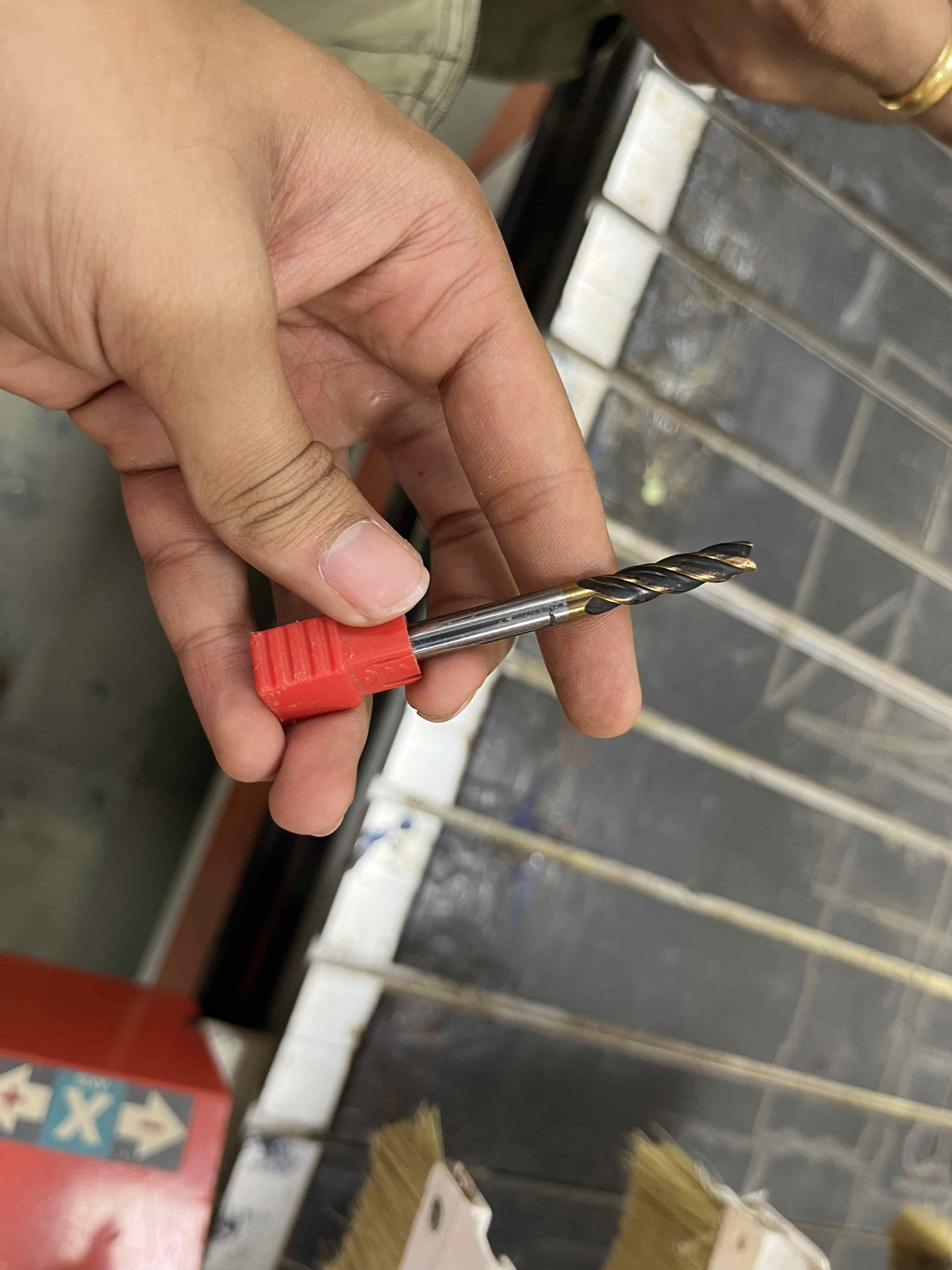
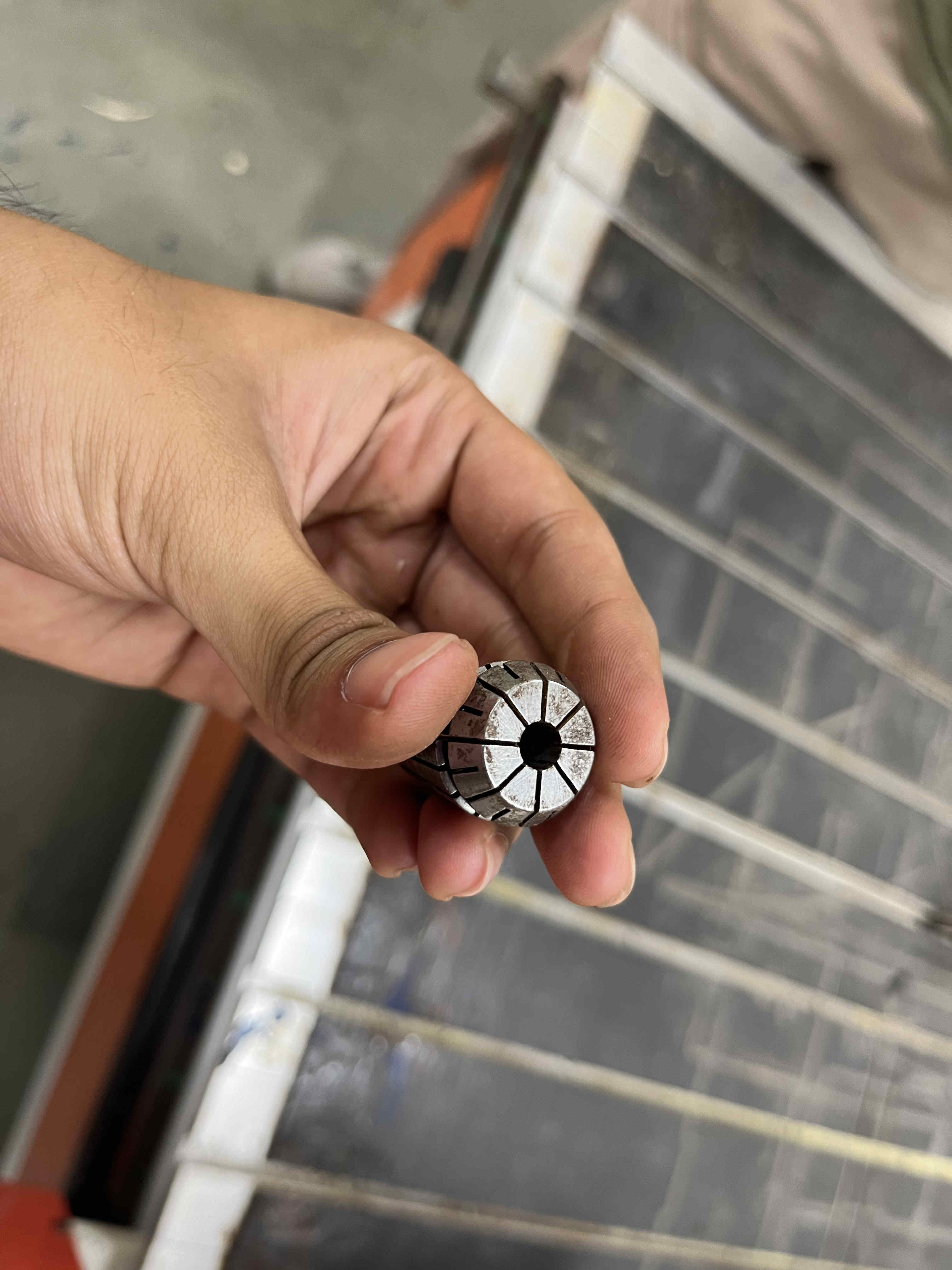
Attatching collet and drill bit
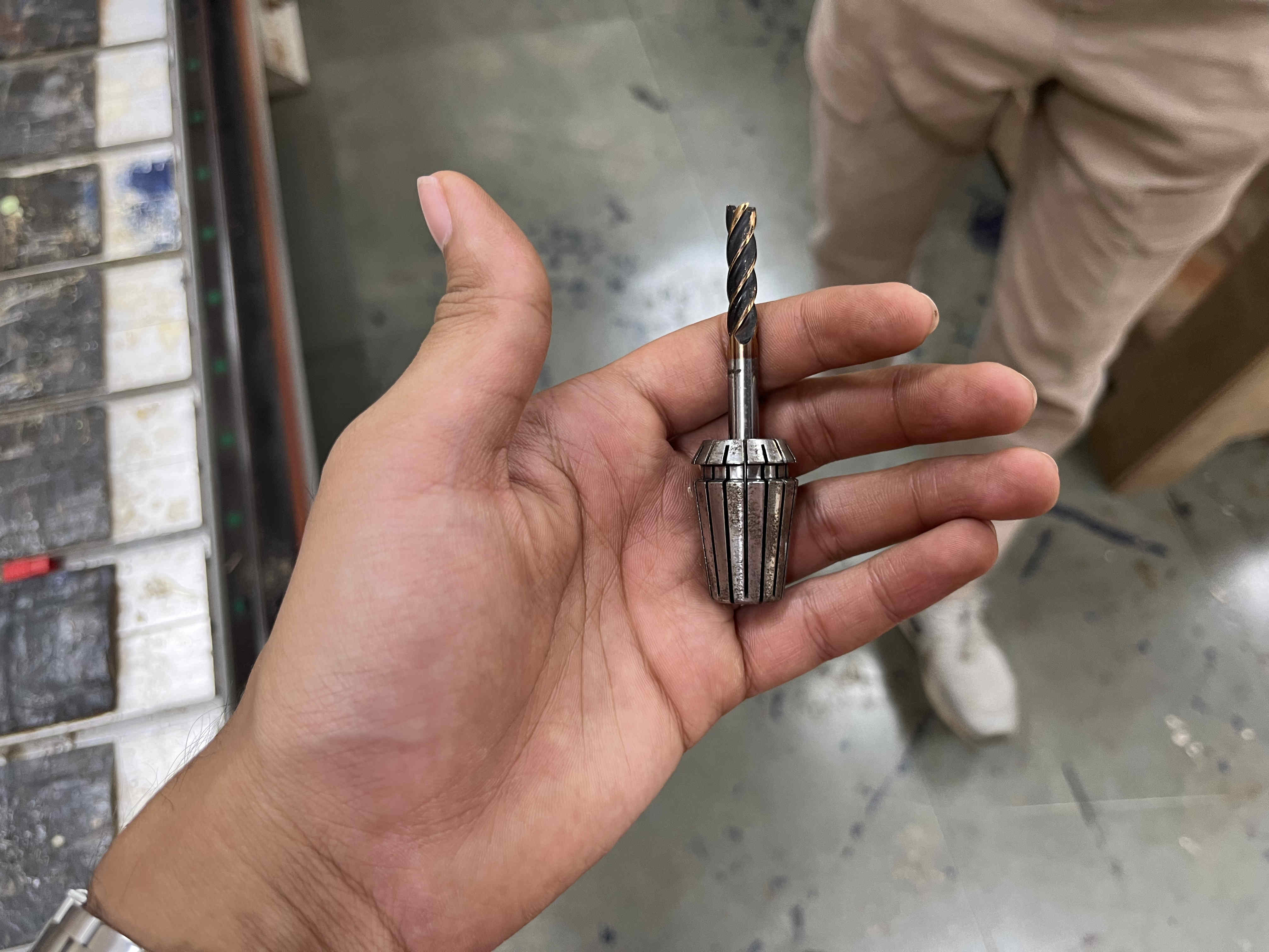
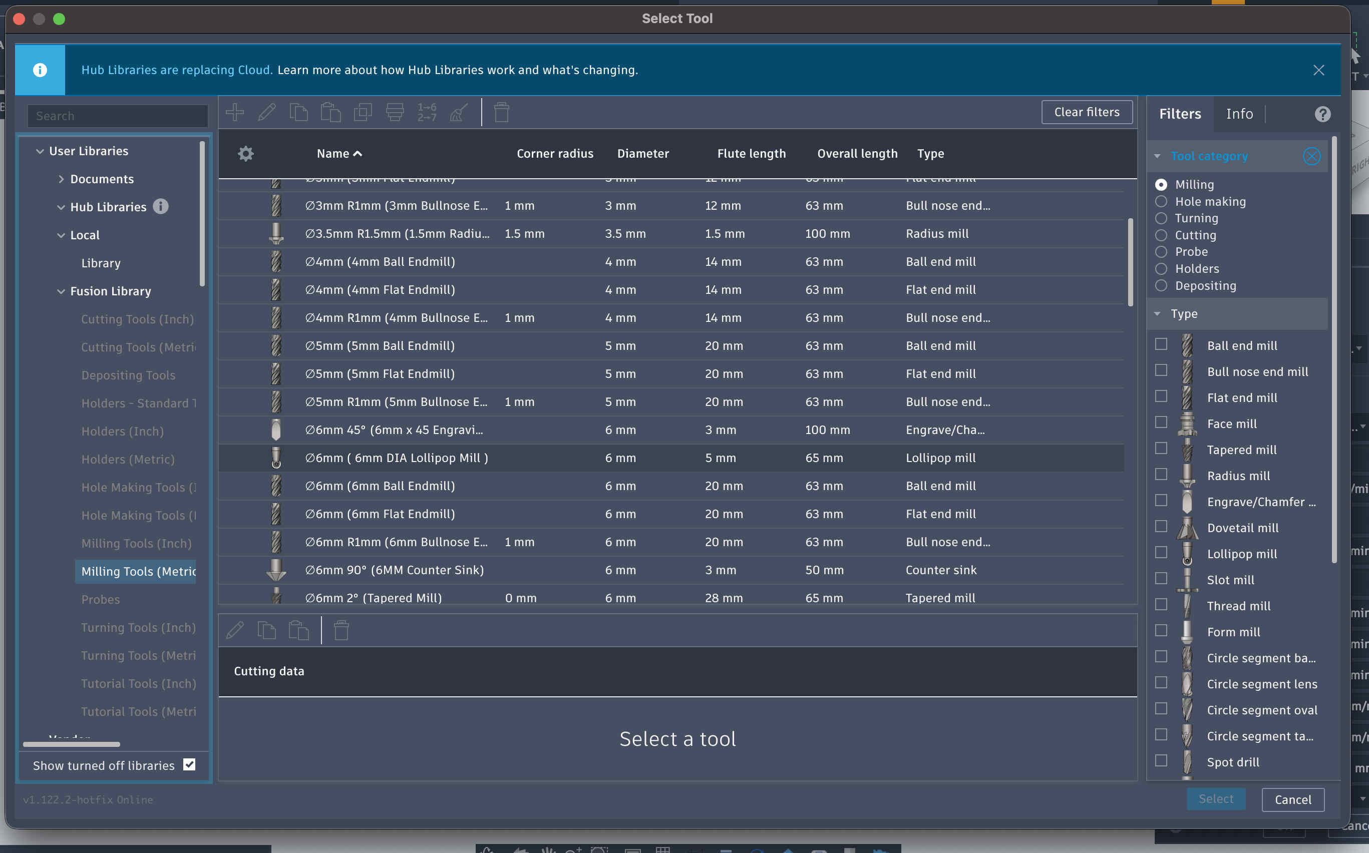
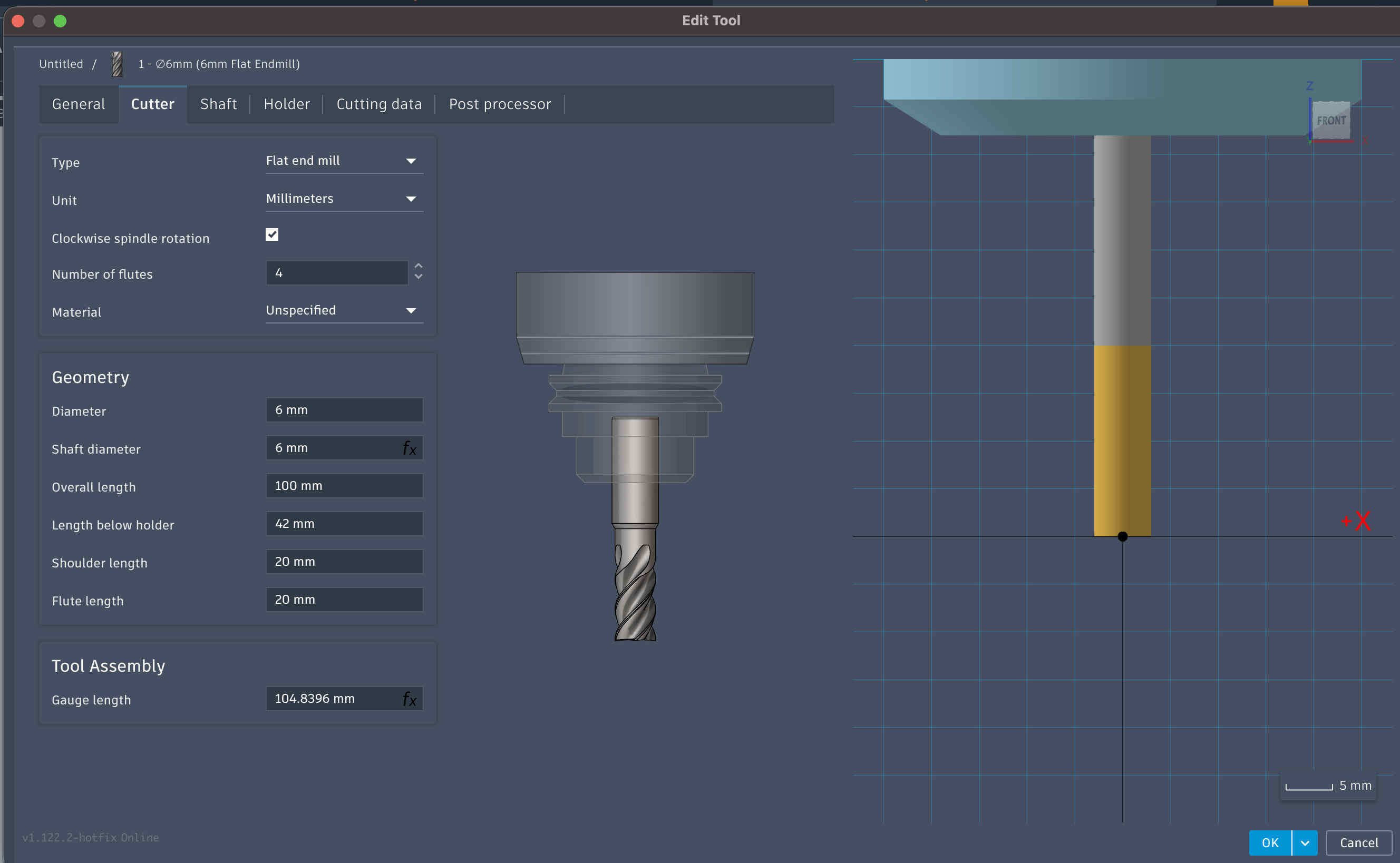
Drill bit that we will be using for all my cuts
6mm Flat end mill
Other details are mentioned in the following picture
Collet to attatch the drill bitThe drill bit attatches to the collet as suchThe contraption can be clicked into the spindle then to be tightened with a hex nutAttatched bit and collet
Make sure the bit is tight but not tooo tight,
This is becasue metals expand when they heat, Causing trouble when you want to remove the bit
Also , over thread tightening a screw is never a good idea
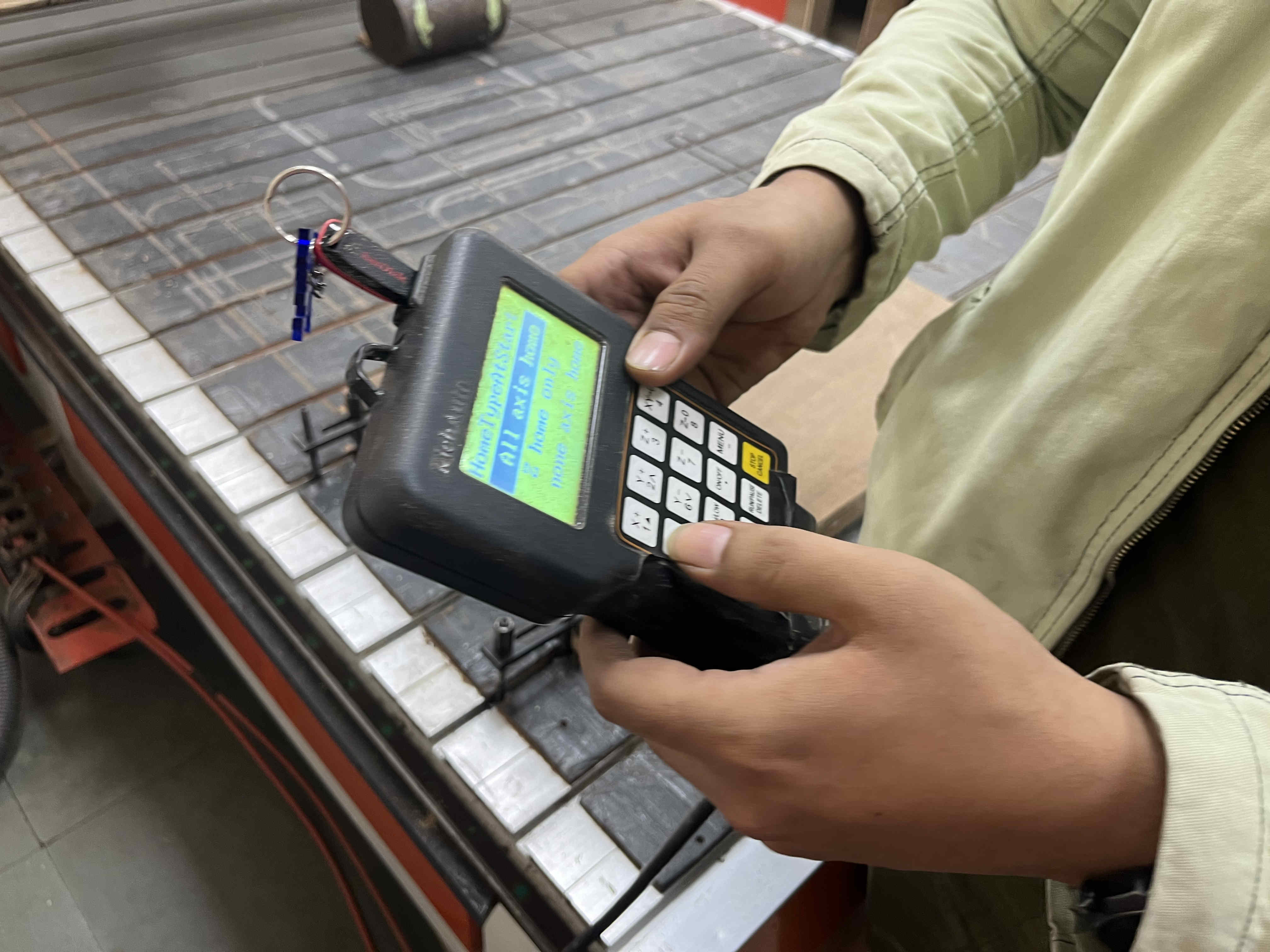
homing Z axis.
Trick to home Z axis
Take a piece of paper, keep bringing the z axis down slowly
Then Move the piece of paper
Do this until the piece of paper BARELY moves,
Make sure it moves, anything beyon nessecary will rip the paper,(we want a level just below this stage)
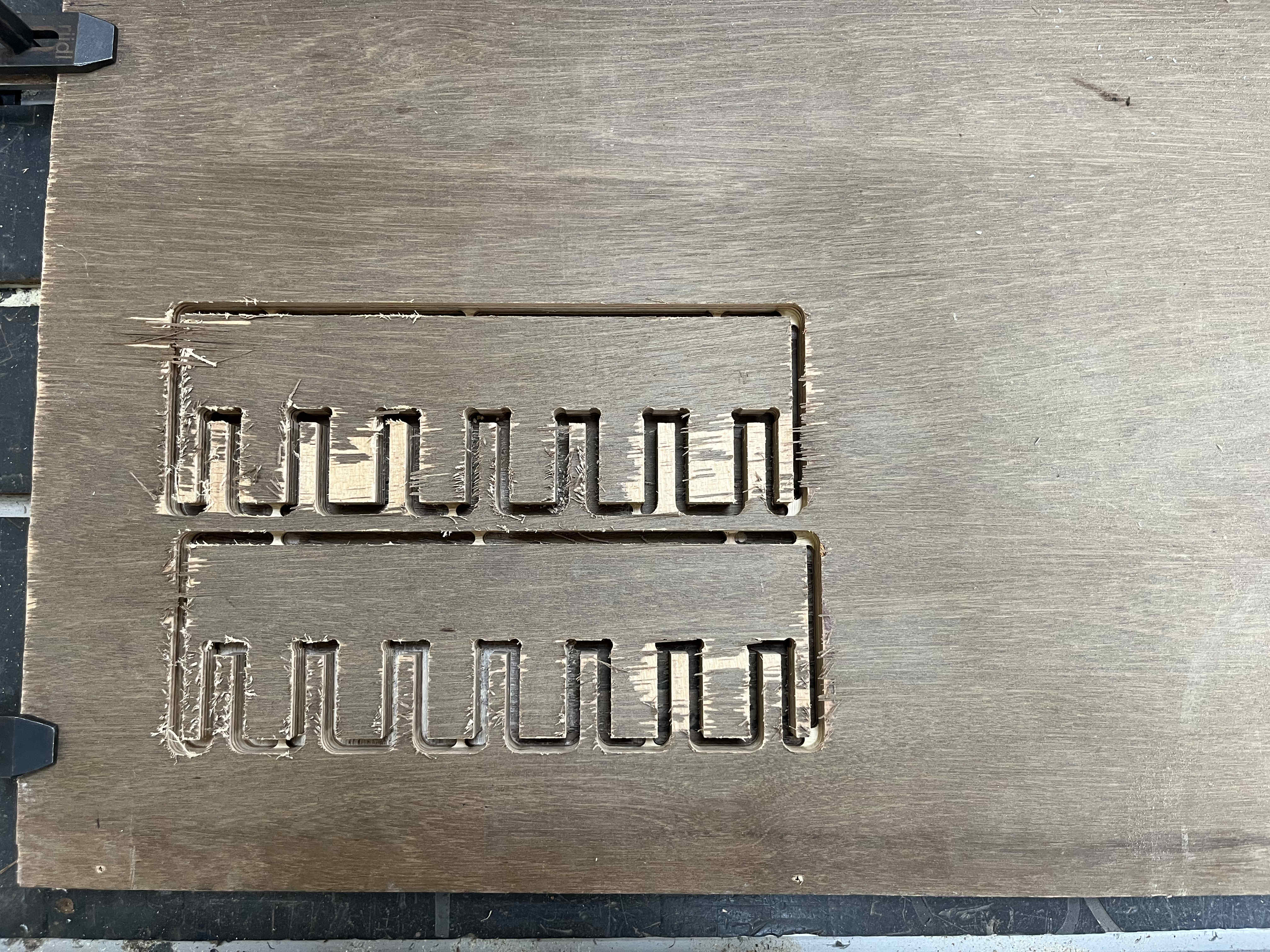
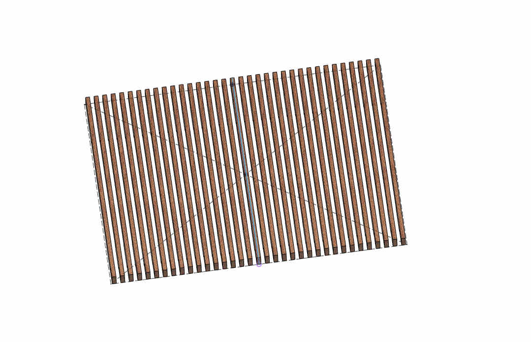
COmb test- 18 mm ply
Now we create a test file to test tolerences on a sheet of plyFirst step is creating the file
The basic concept behind this test is making postive tolerance widths and negative tolerance fits to try different types of friction Fits.
The middle tooth can be the average thickness of the ply we need to cut on, (we will name this t)
The next tooth needs to be the width of ply thickness+ tolerance(t+tol)
And then the following one can ve ply thickness + 2* toleracne(t+ 2tol)
so on and so forth....
The avg thickness for my ply was 19.04, you can see the values for tolerances accordingly
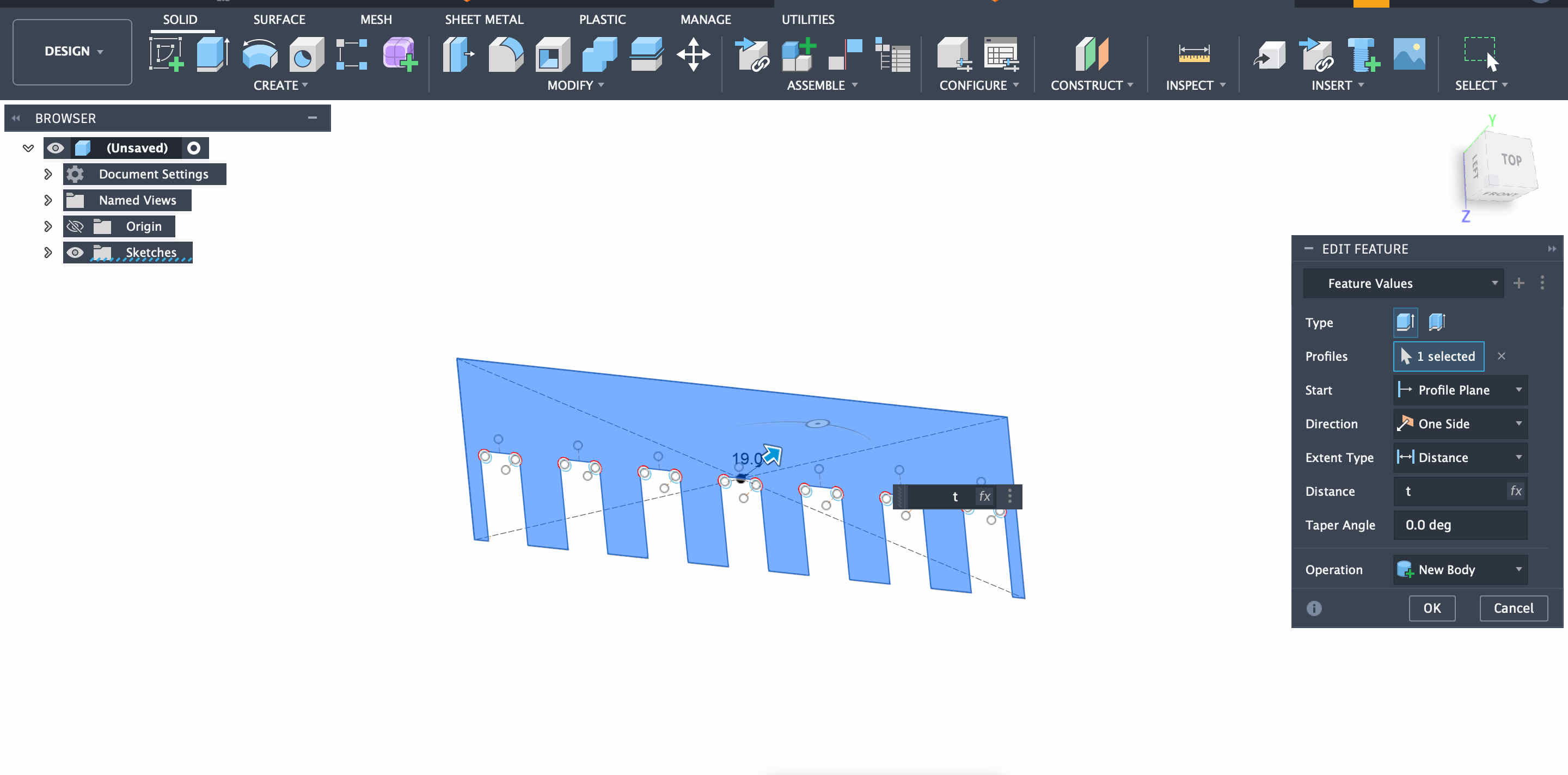
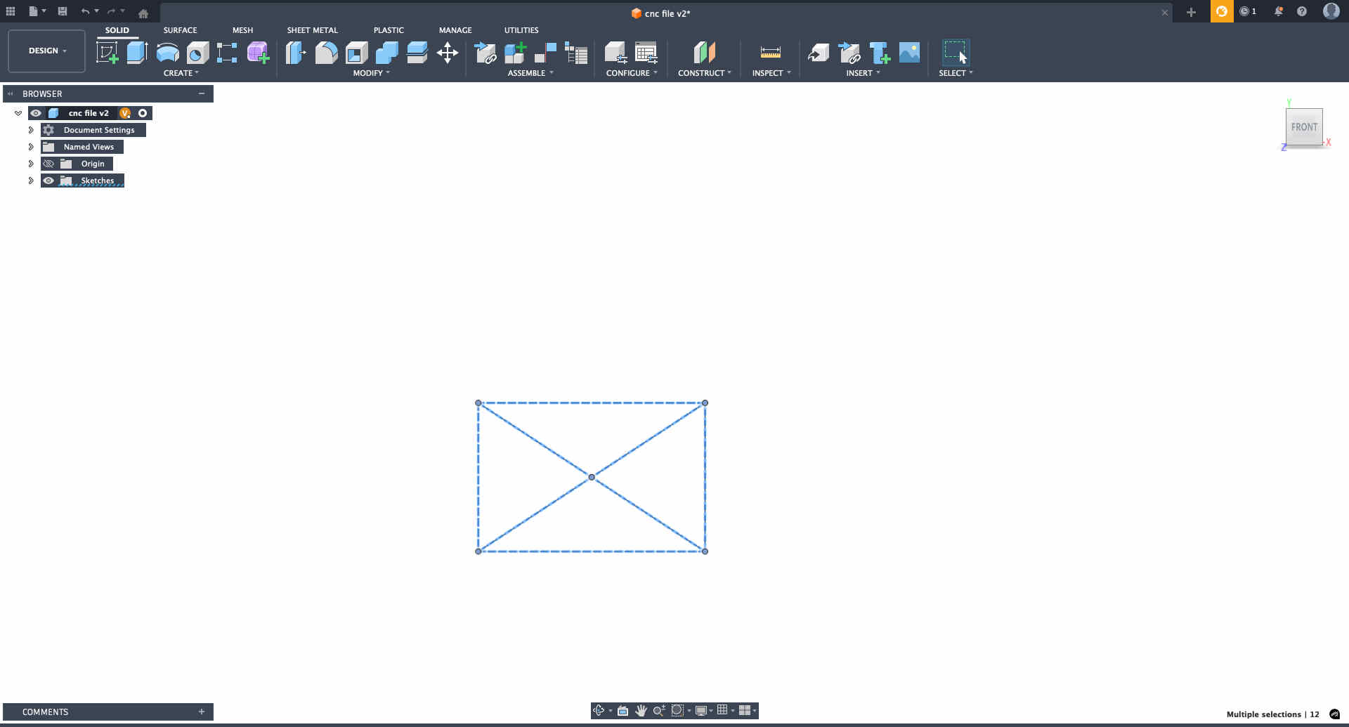
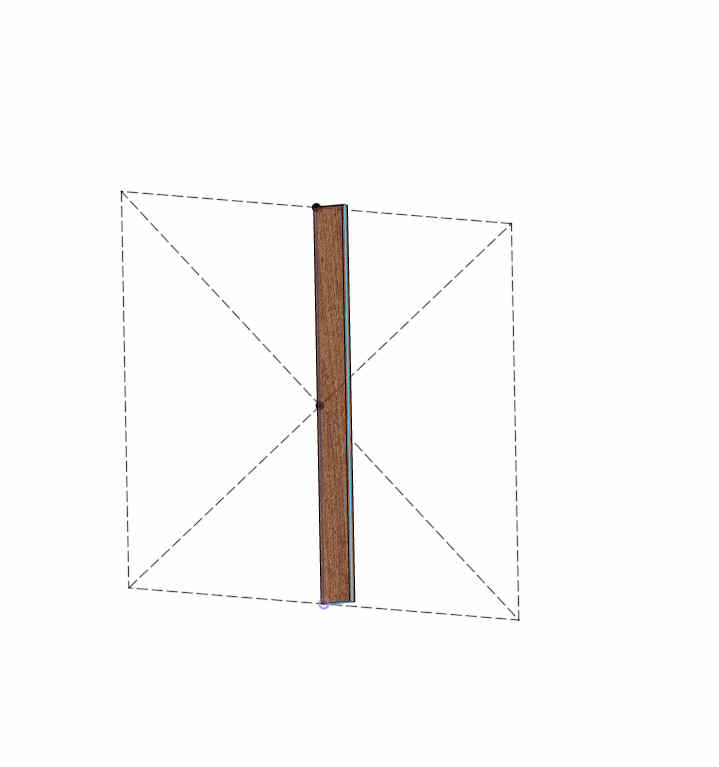
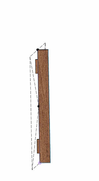
Creating dogbones for better cuts
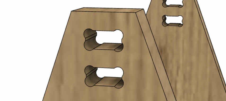
What are dog bones-
Dog bones in CNC wood cutting are small, rounded, dog-bone-shaped cutouts added to internal corners of joints to accommodate the circular radius of a router bit
This is what it looks like
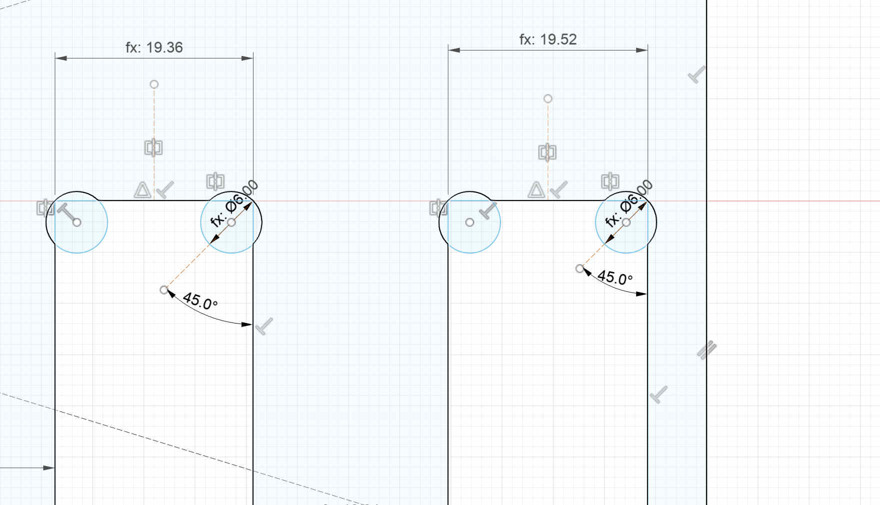
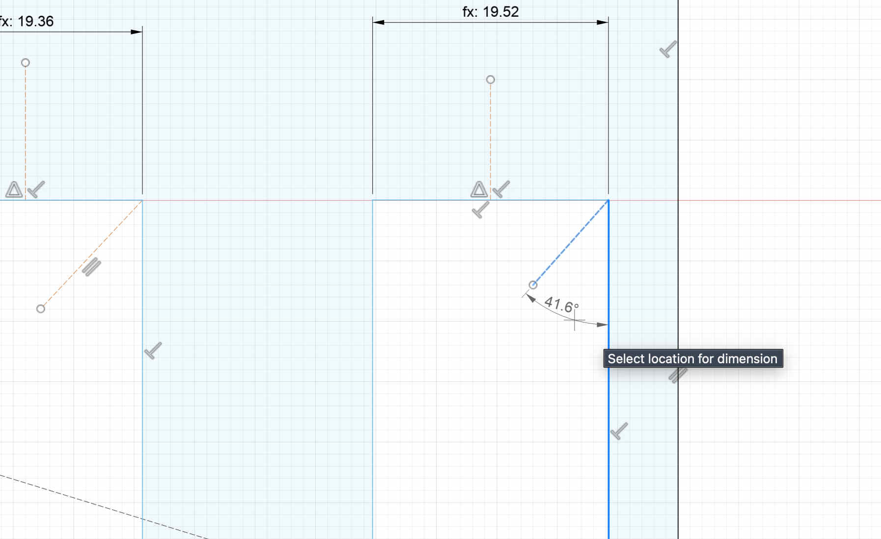
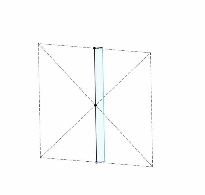
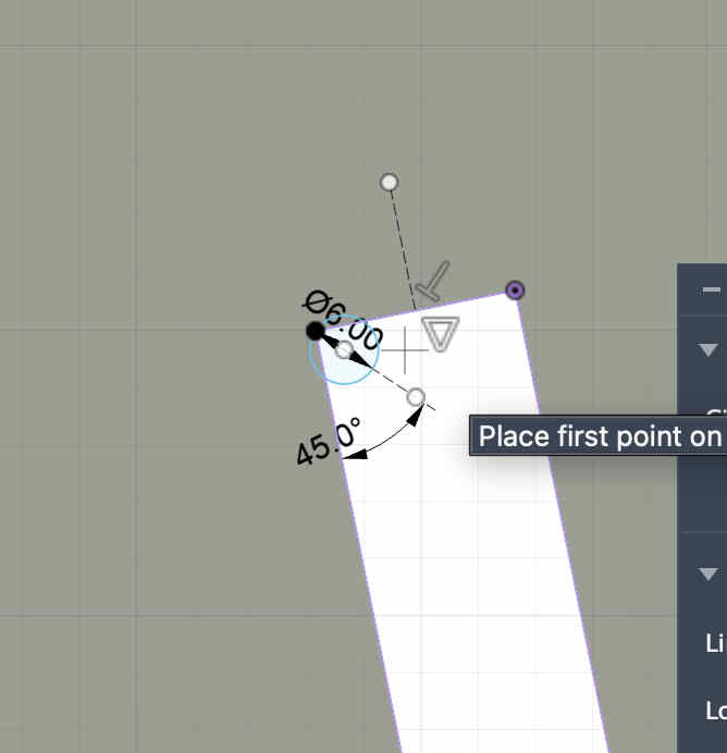
we need to create circles around tight corners as suchFor this we create a 45 degree diagnol from the edge, and create a 2 point circle of diameter 6mm(our flat end mill size). connecting the edge and the 45 degree diagnolYou can choose mid points of each line anf mirror the circlemake sure not to array pattern repeat the circles, as each width on our path is different Extrude your sketch
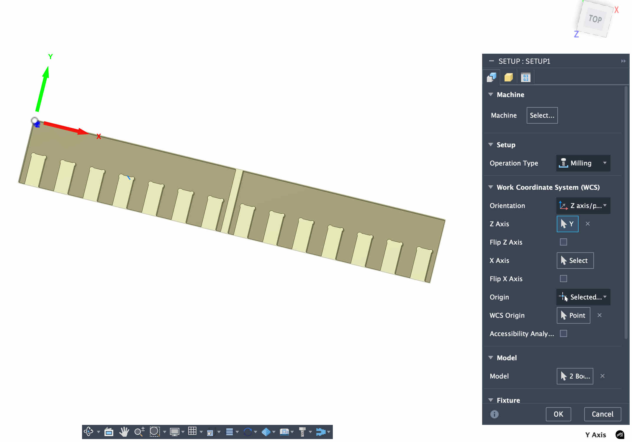
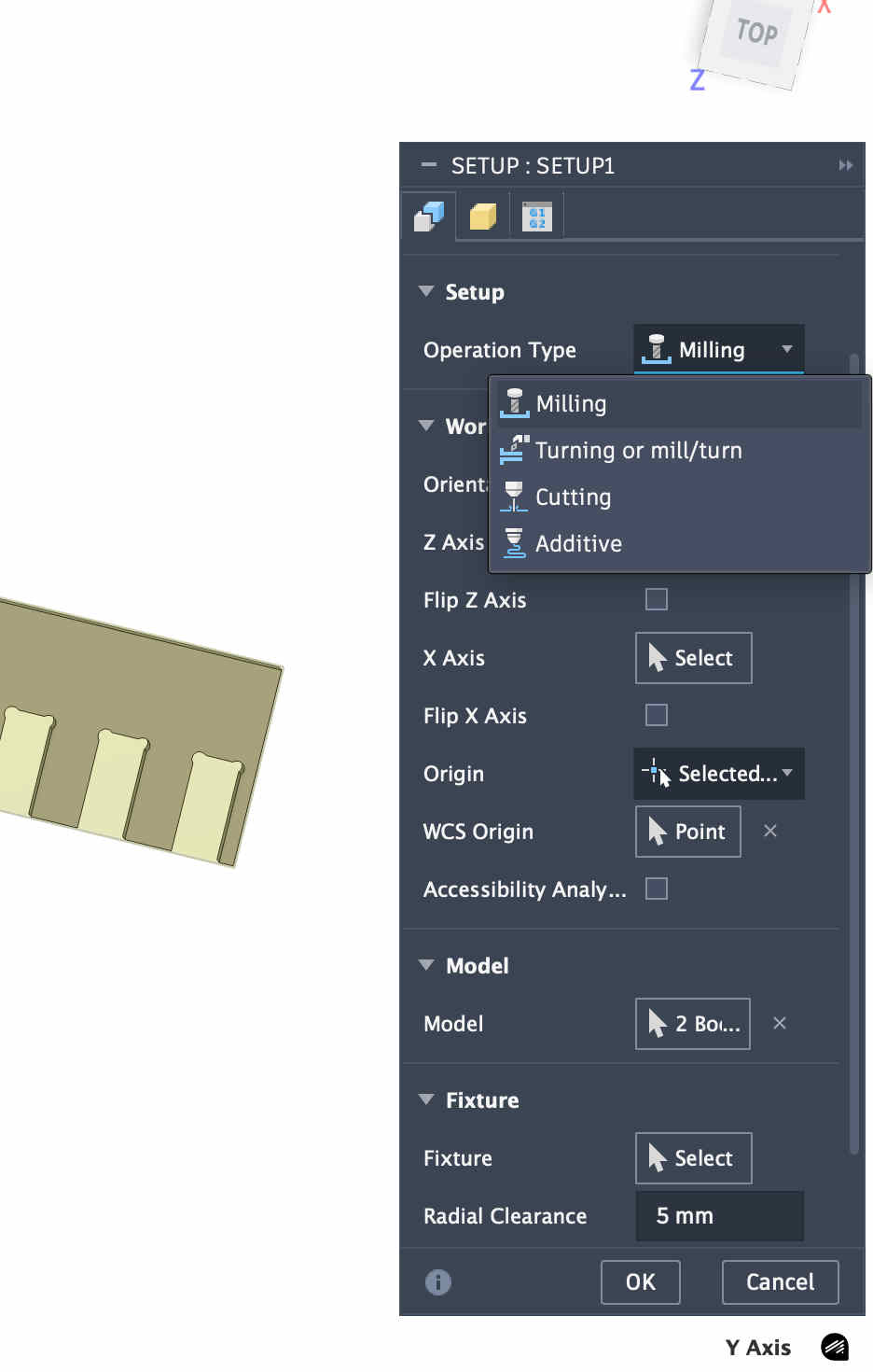
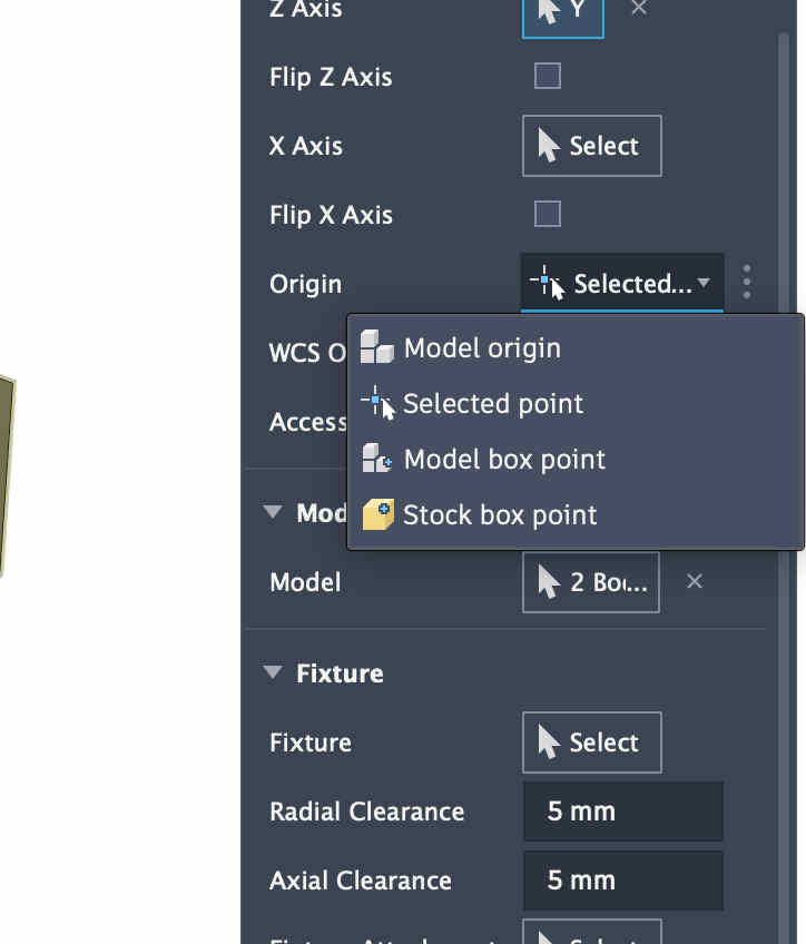
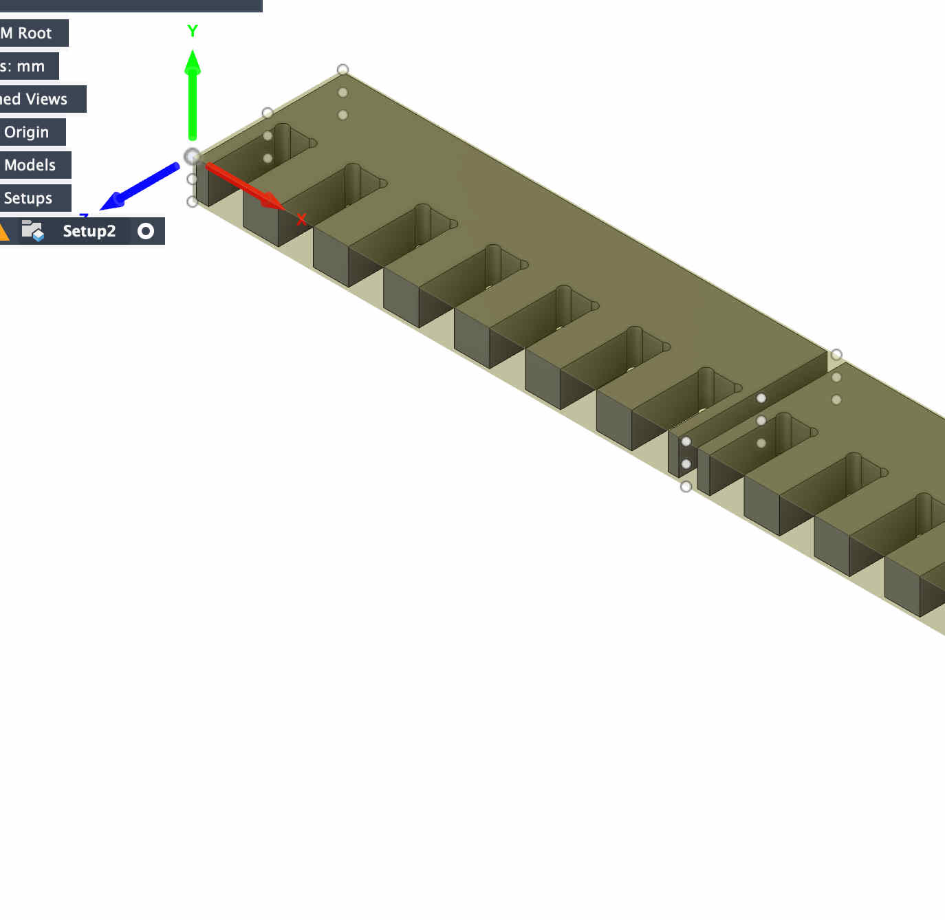
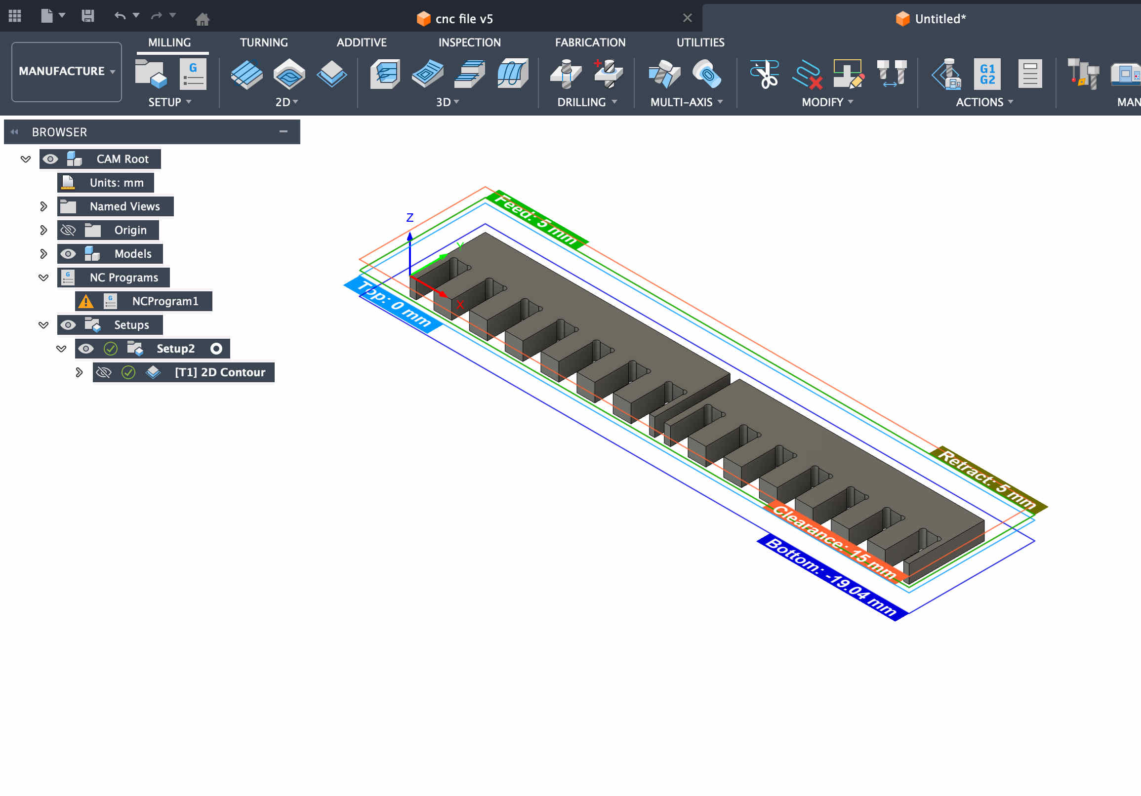
Creating a cam NC file.
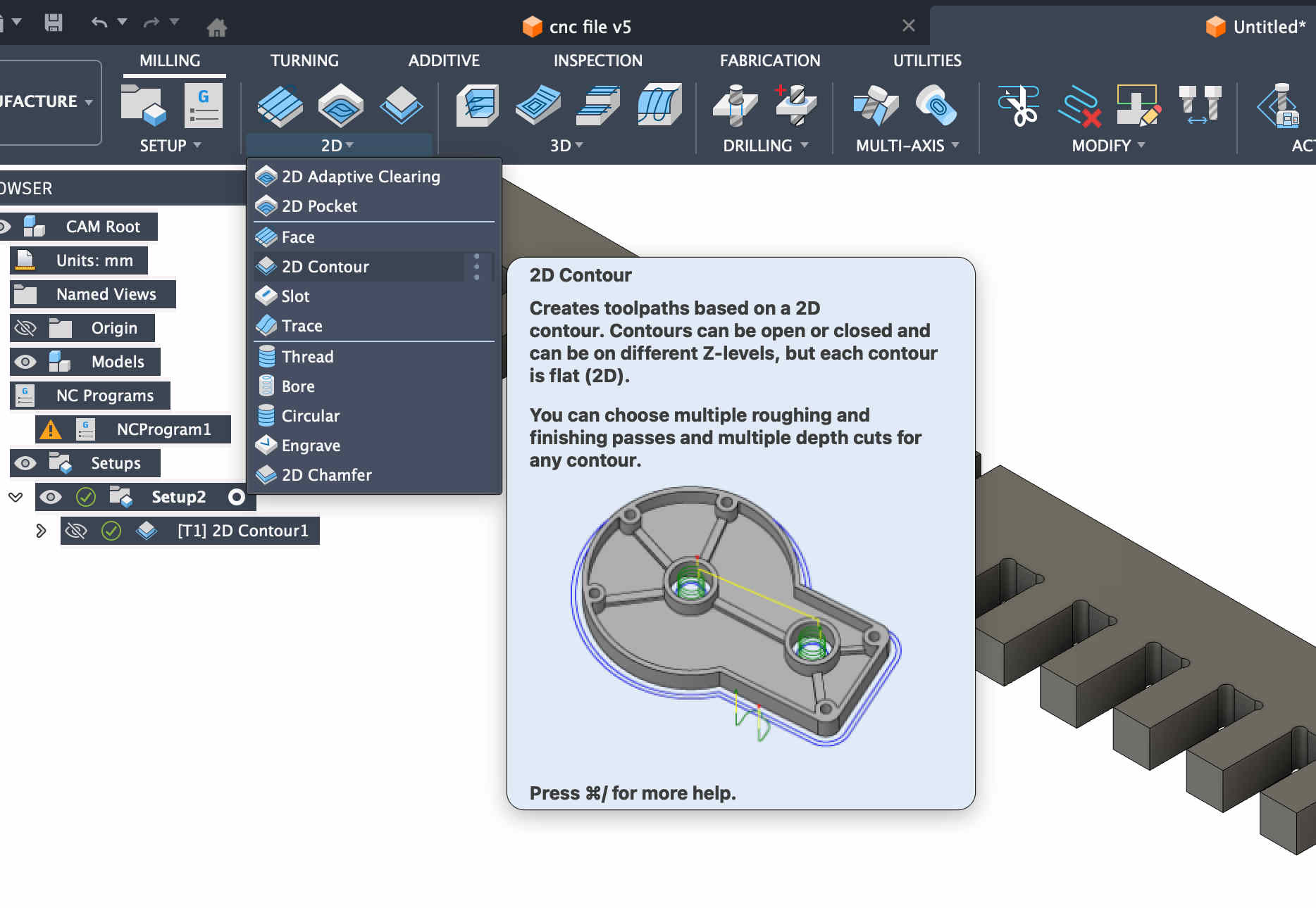
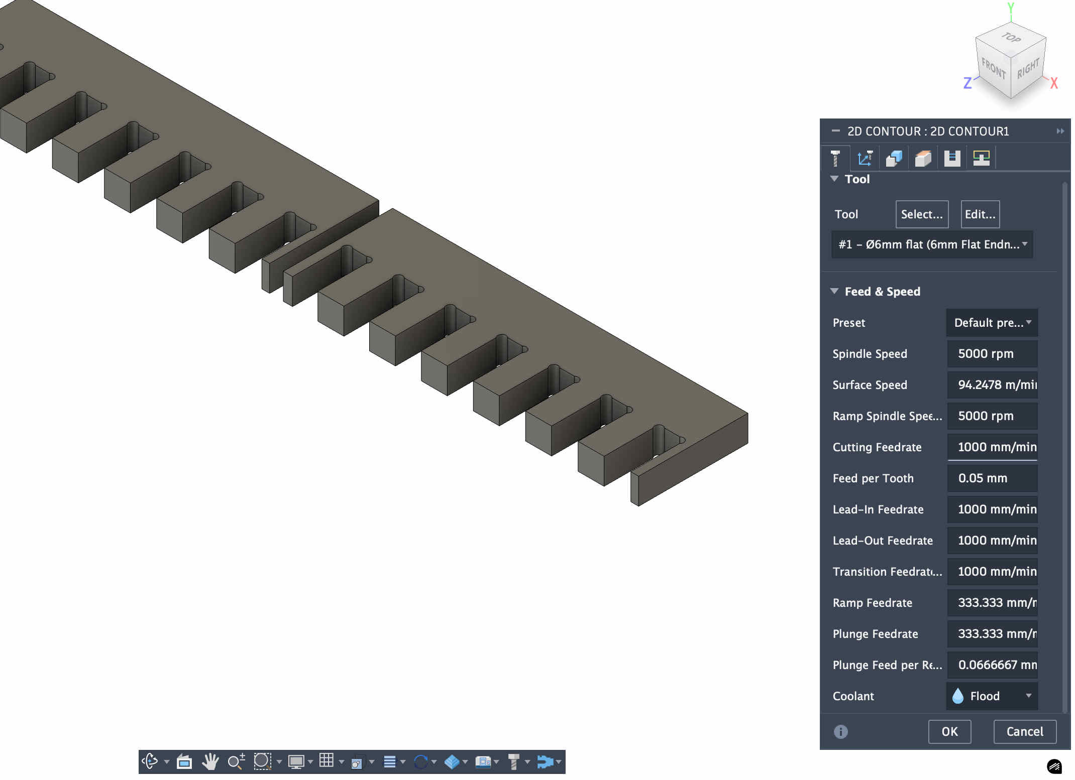
Create a new setupChoose our operation (milling)Now we set originThe origin you select on box point might bejumbled, make sure to orient it correctlyNow we choose a simple 2d contour operation.We can choose our tool in the first panel of setup now
Find the bit that you are using
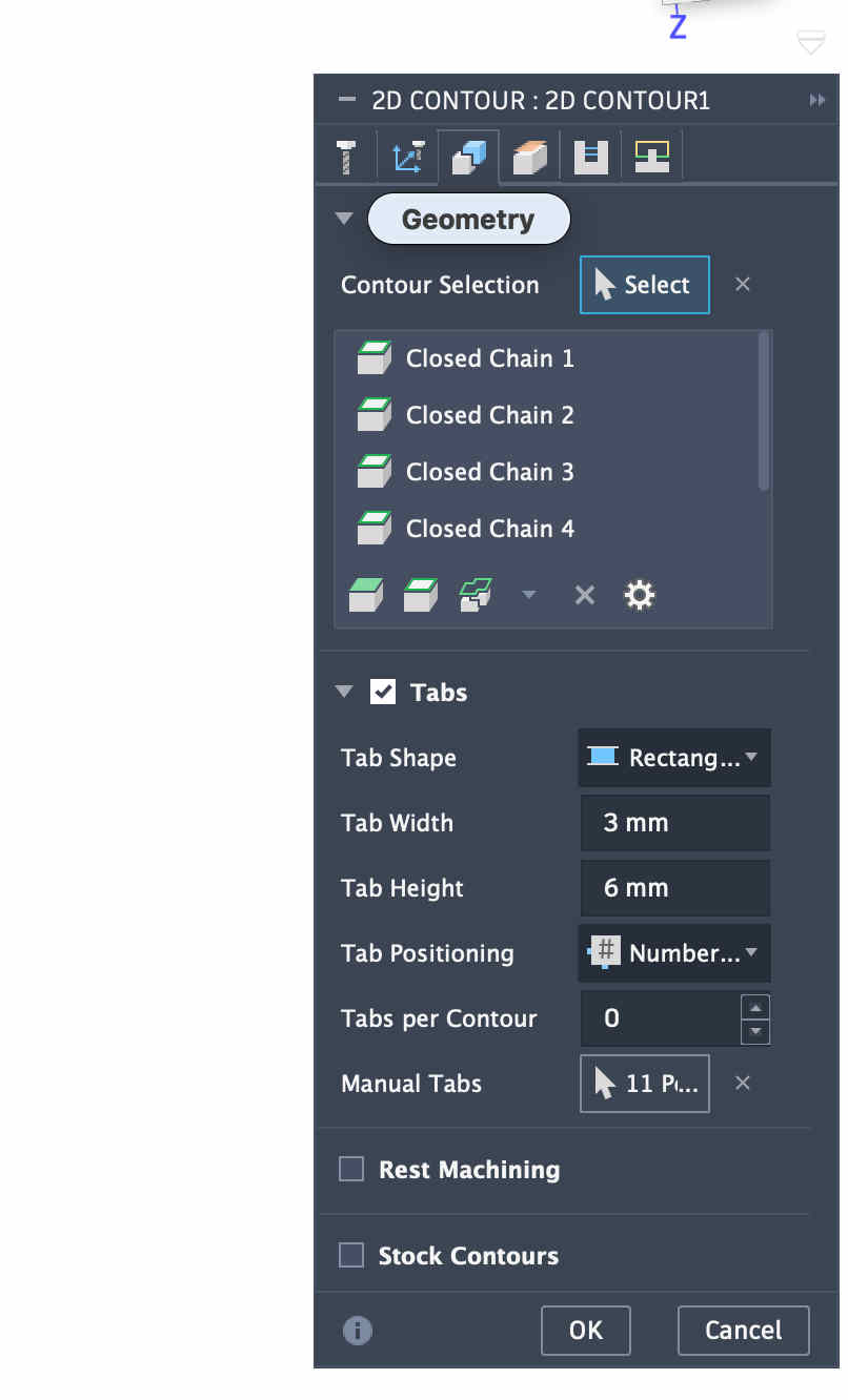
Make sure to cross check the default measurements of your bit, you can edit cutter parameters after accurately measuring your bit with a verneer caliper.The operation panel looks something like this inn fusionBasic rule of thumb is to set and solve all requiremnts from left to right on all of the tabs as seen in the pictureAdding tabs is super crucial
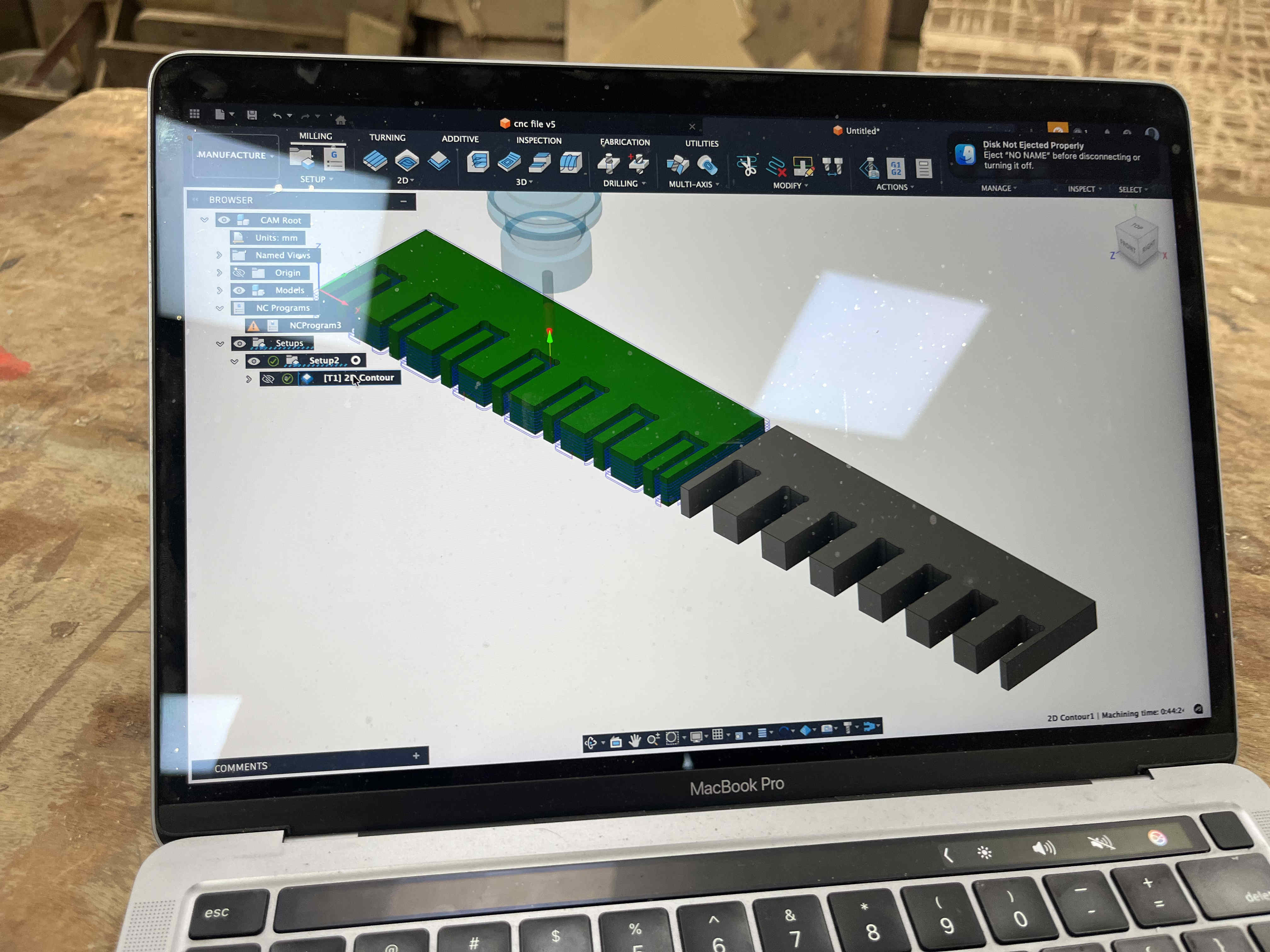
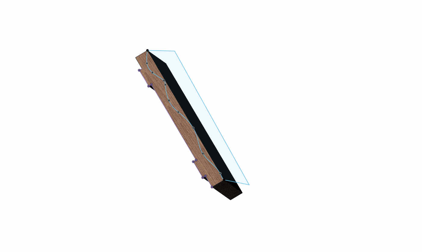
Tabs
When your designed piece is being machined and cut out, in the end layers as the contact between piece and the big sheet of ply gets low the piece can start moving
This can cause a plethora of issues, as a moving piece near a bit rotating at 9000 rpm, can cause serious kickback, more issues like the bit breaking and more,
Inaccuracy of piece will be the least of your issues
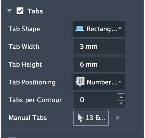
I suggest keeping thin, but tall tabs,
This makes cleaning the part post easier and stronger tabs
General rule of thumb can be 1/3 of your total thickness can be your tab height and 3 to 4 mm can be your tab width
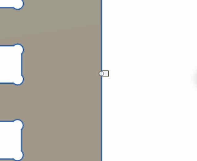
tabs preview, placing them manually to avoid tabs on intersecting joints surface.Setting bottom height as stock bottom
Set roughing depths according to you, here I have set it as 2 mm
once done your operation should pop up on the left window
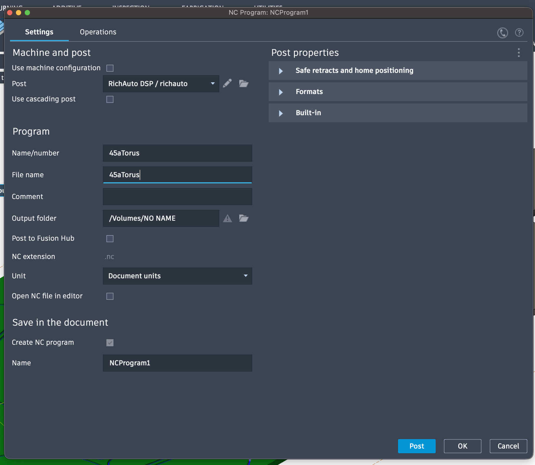
Right click on it and say create nc program
export nc program to flash drive and enjoy
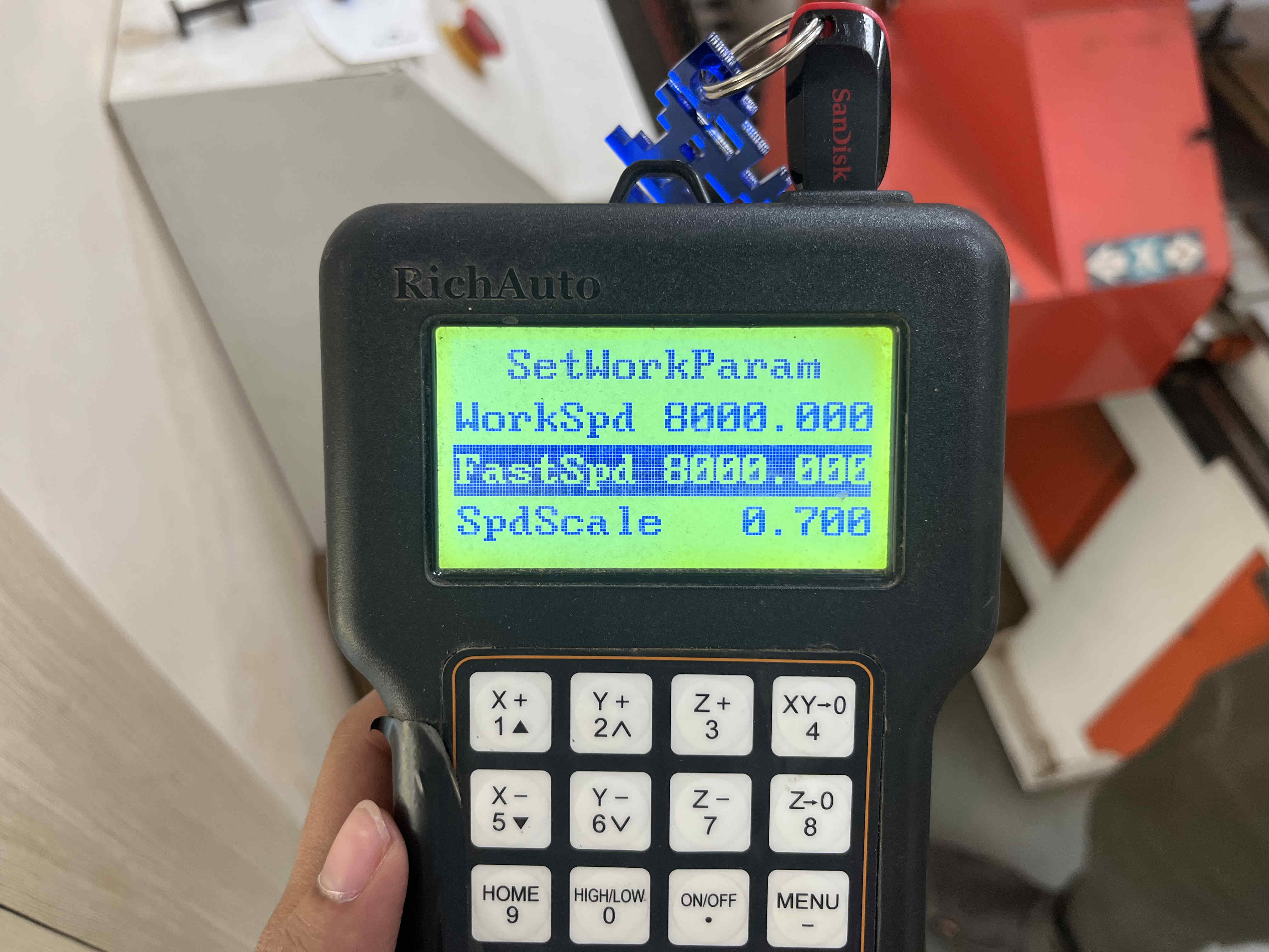
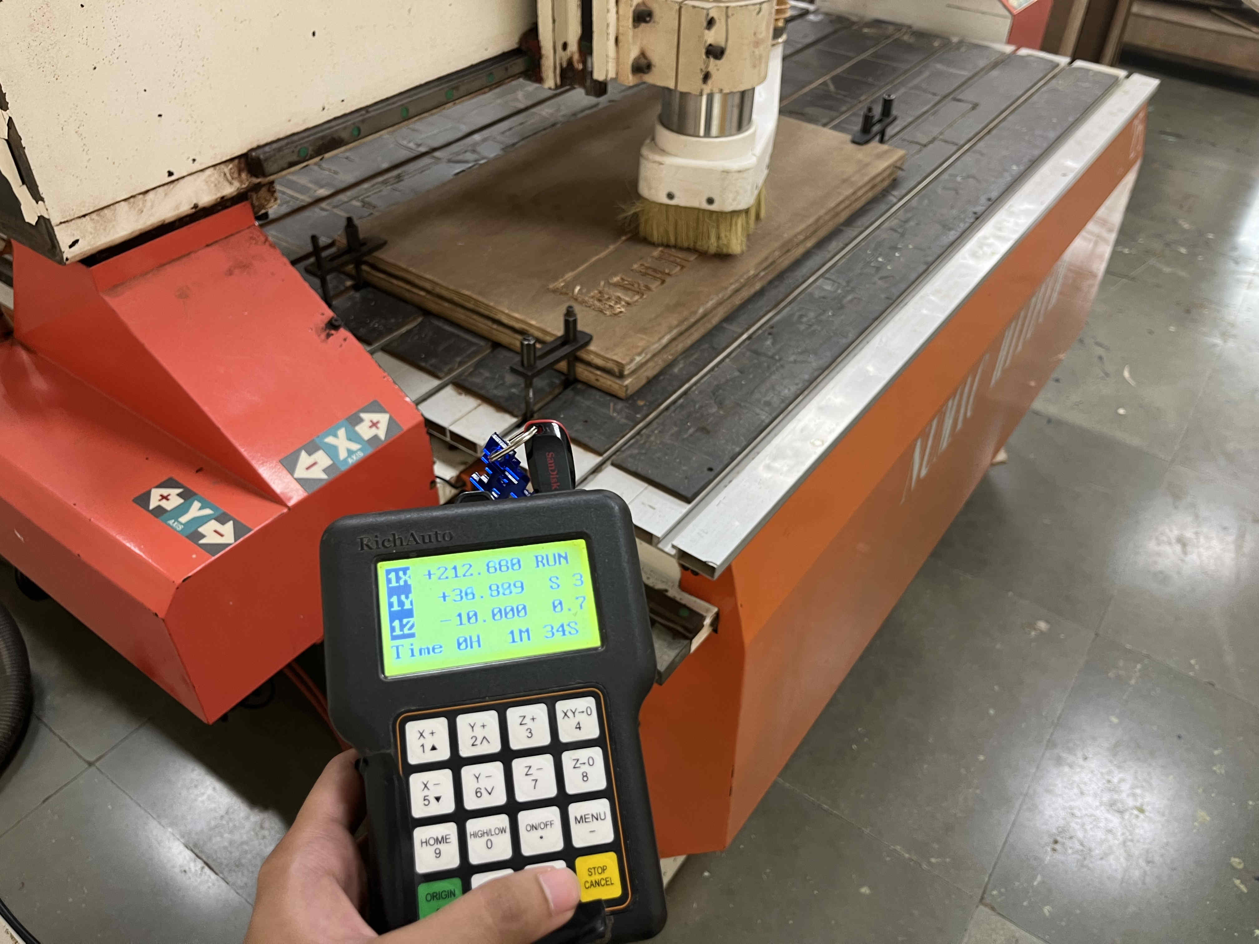
Plank set up and clamped as discussed earlierInserting and reading file on uDiskAfter selecting your operation, you can manually change the work speed and fast speed if needed
Workspeed refers to the speed of the cut,
Whereas fastspeed refers to the speed of moving from one piece to another
You can change the cutting feed rate (spdscale) during the cut as well
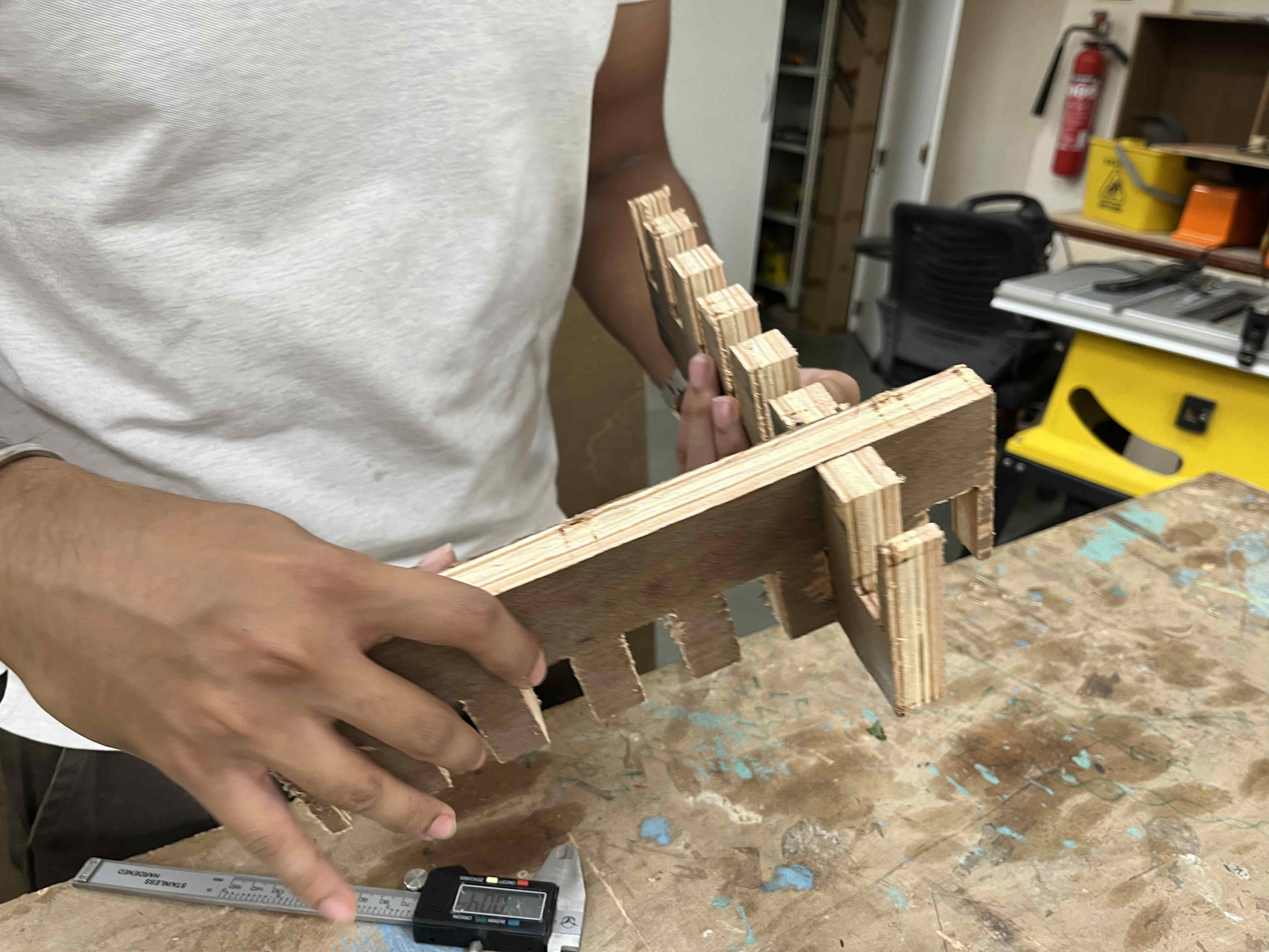
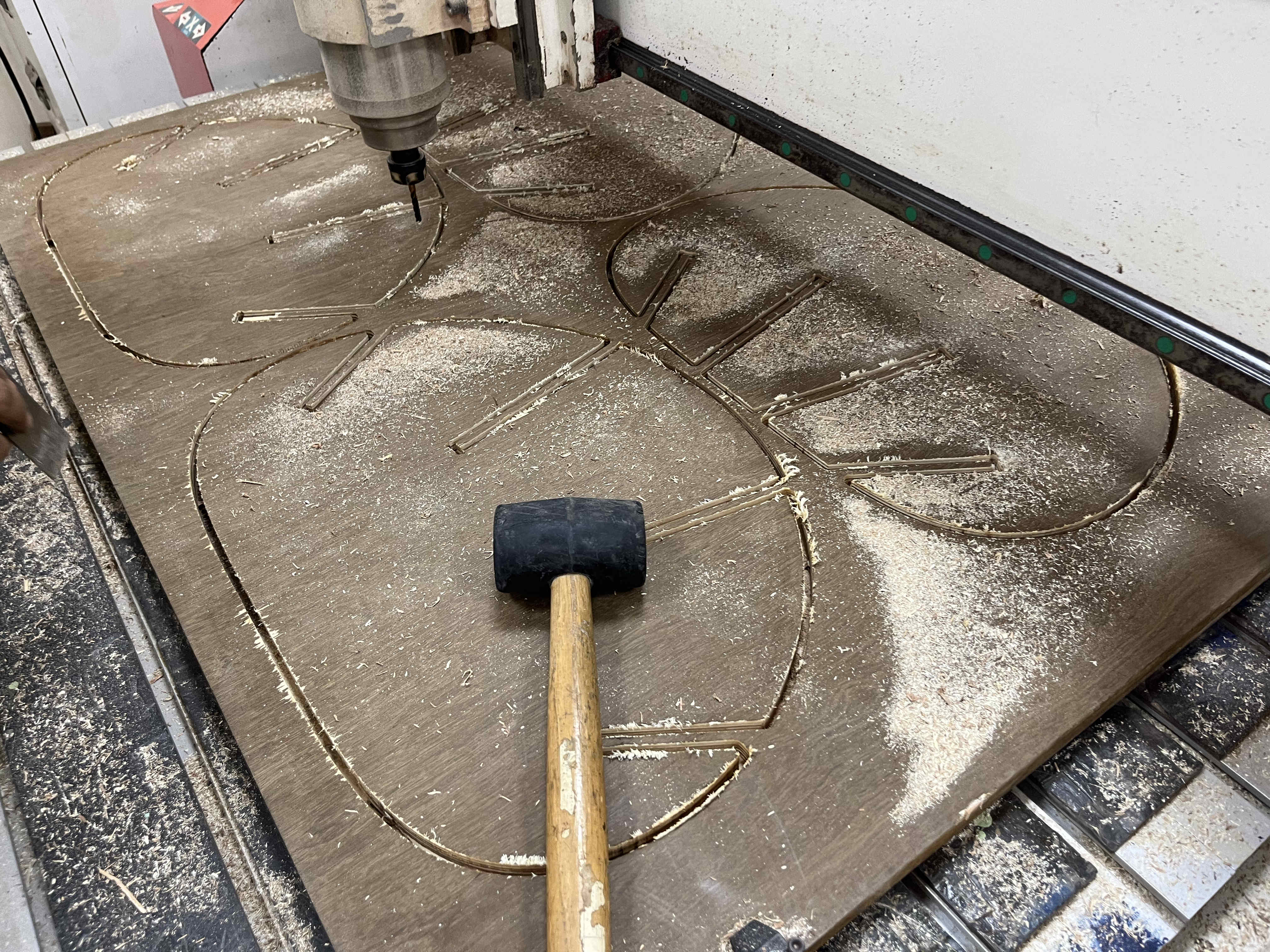
Cutting the pieceKeeping hands on pause and mind focused on the cut to avoid any mishapsI cut the top piece with a workspeed of 12000 rpm, and the bottom piece as 8000 rpm
at 12000 the ply splintered quite a lot more, so I decided to cut final piecees at 8000 rpm
We found t+2tol to be the best fit, with tol as .16mm
. Individual Assignment .
For the Individual assigment i wanted to experiment wih parametric waffle structures
I was thinking a small stool or an automan with the design structure of a waffle structures
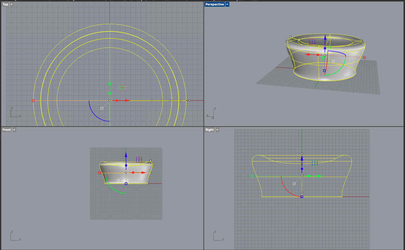
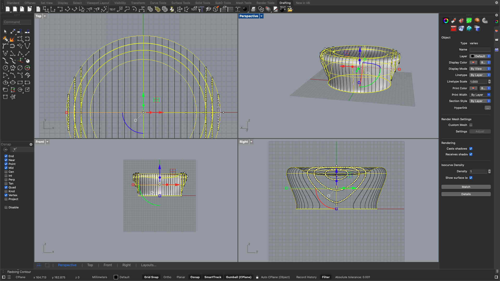
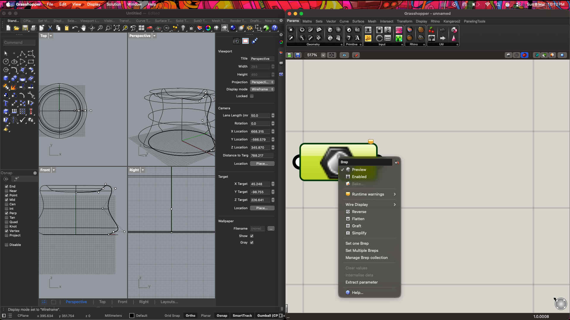
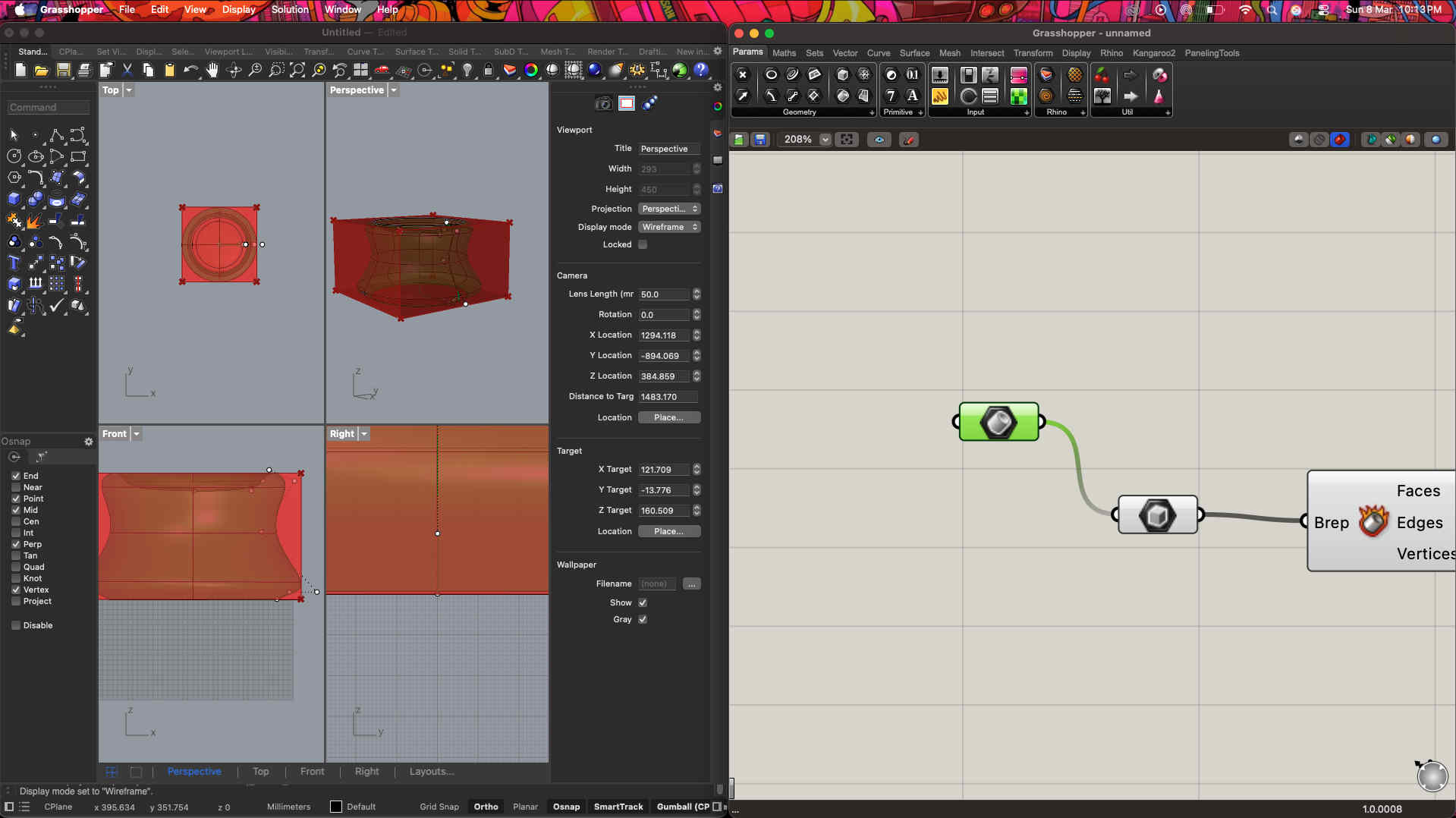
First we create a revolved surface on rhinoClick contour command and devide the surface into multiple piecesCommand used-
Contour
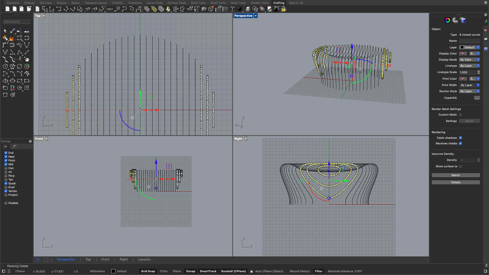
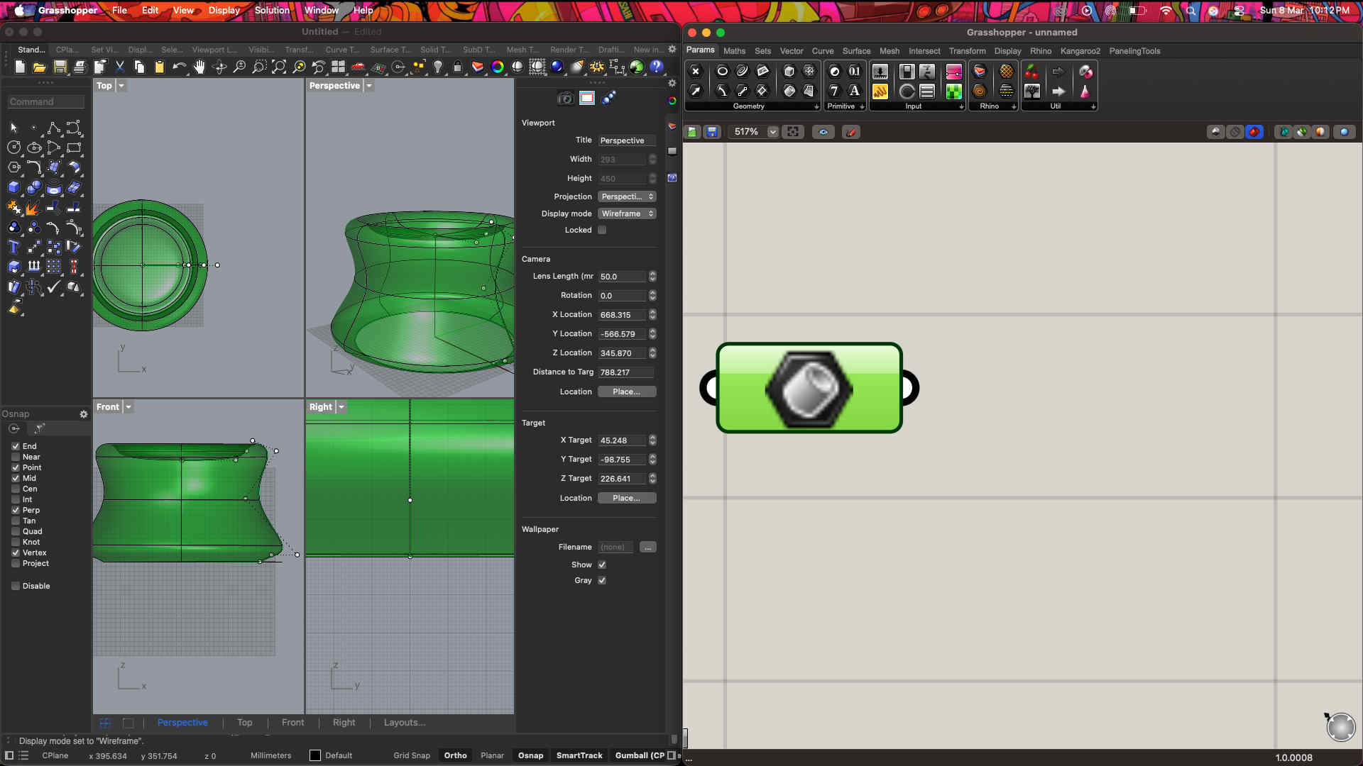
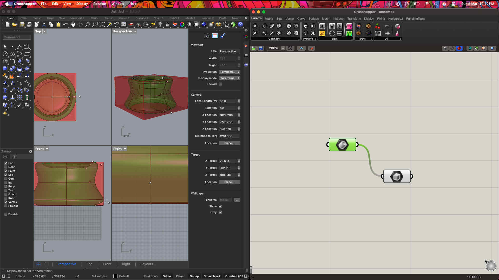
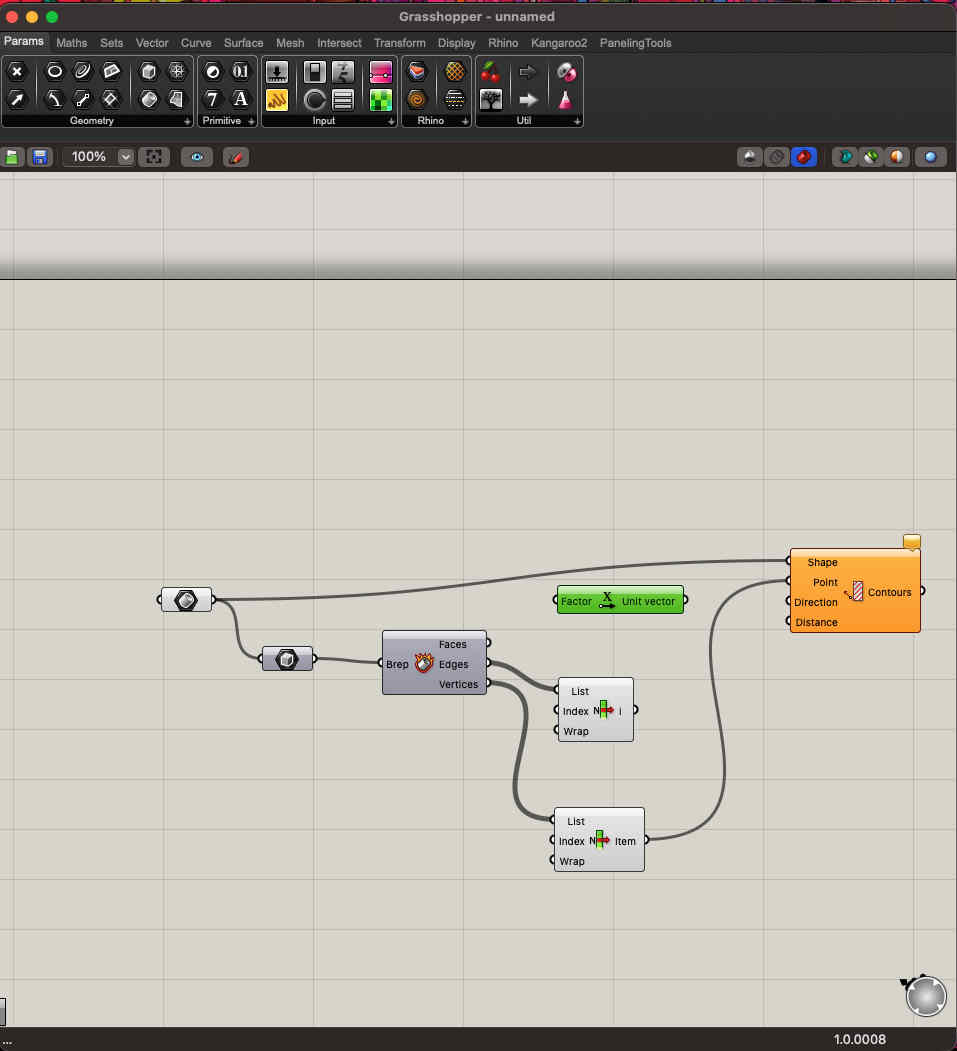
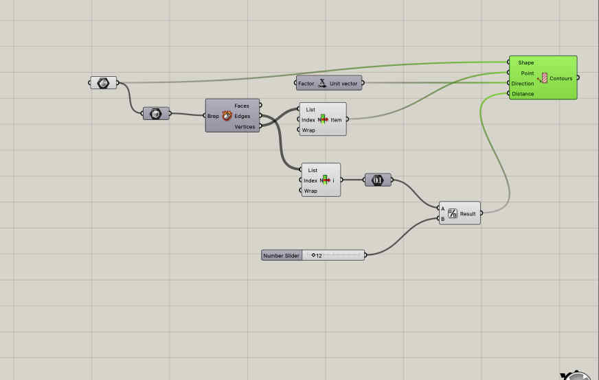
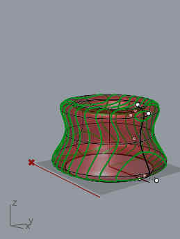
Select all contours and give it a thicknessCommand used - offset srf.This is the resultNow we need the cross structures.Doing so on grasshopper using linked listsmakimg into BRepsError thrown becasue of non feasible geometry
Easy backup file
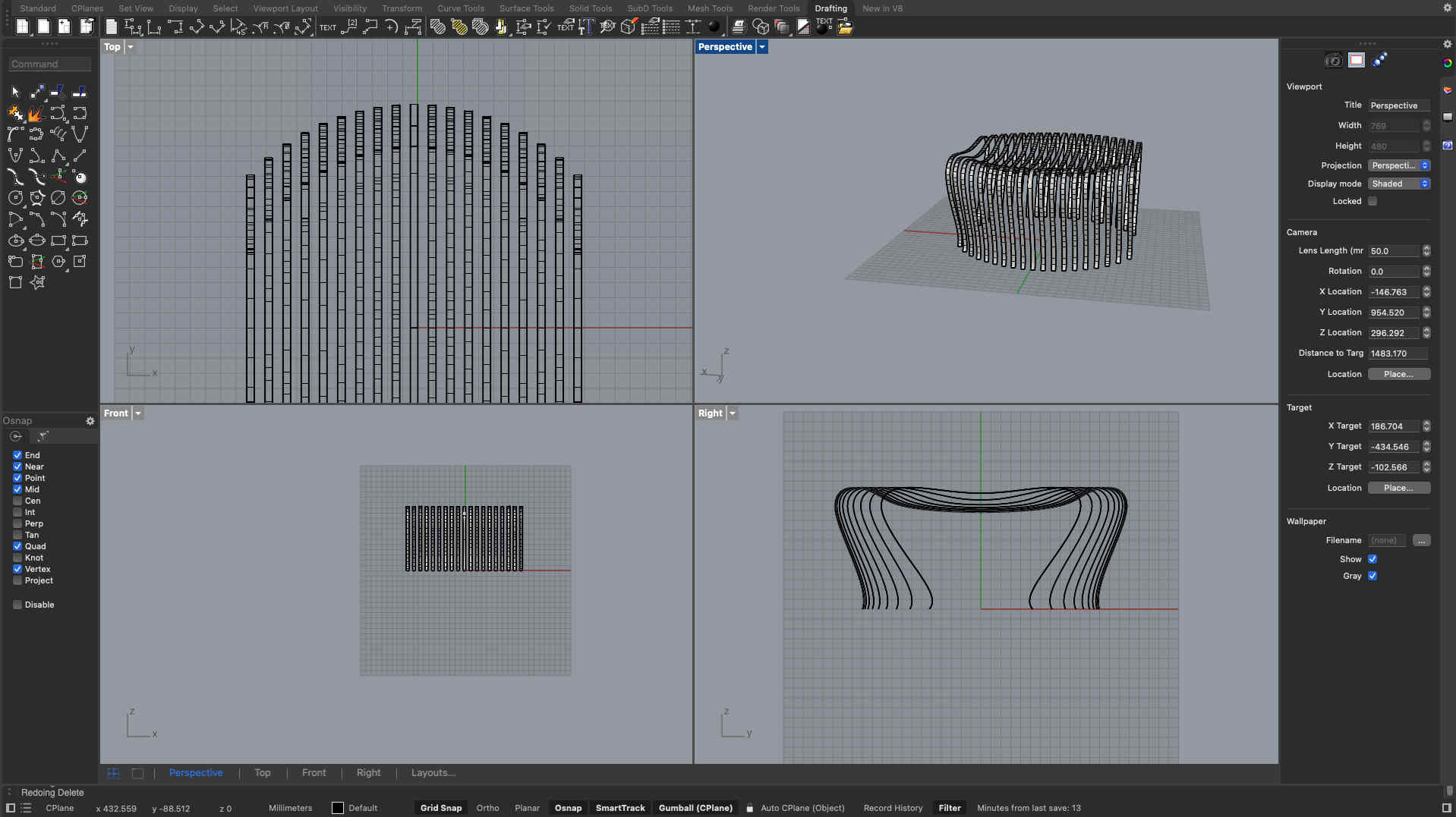
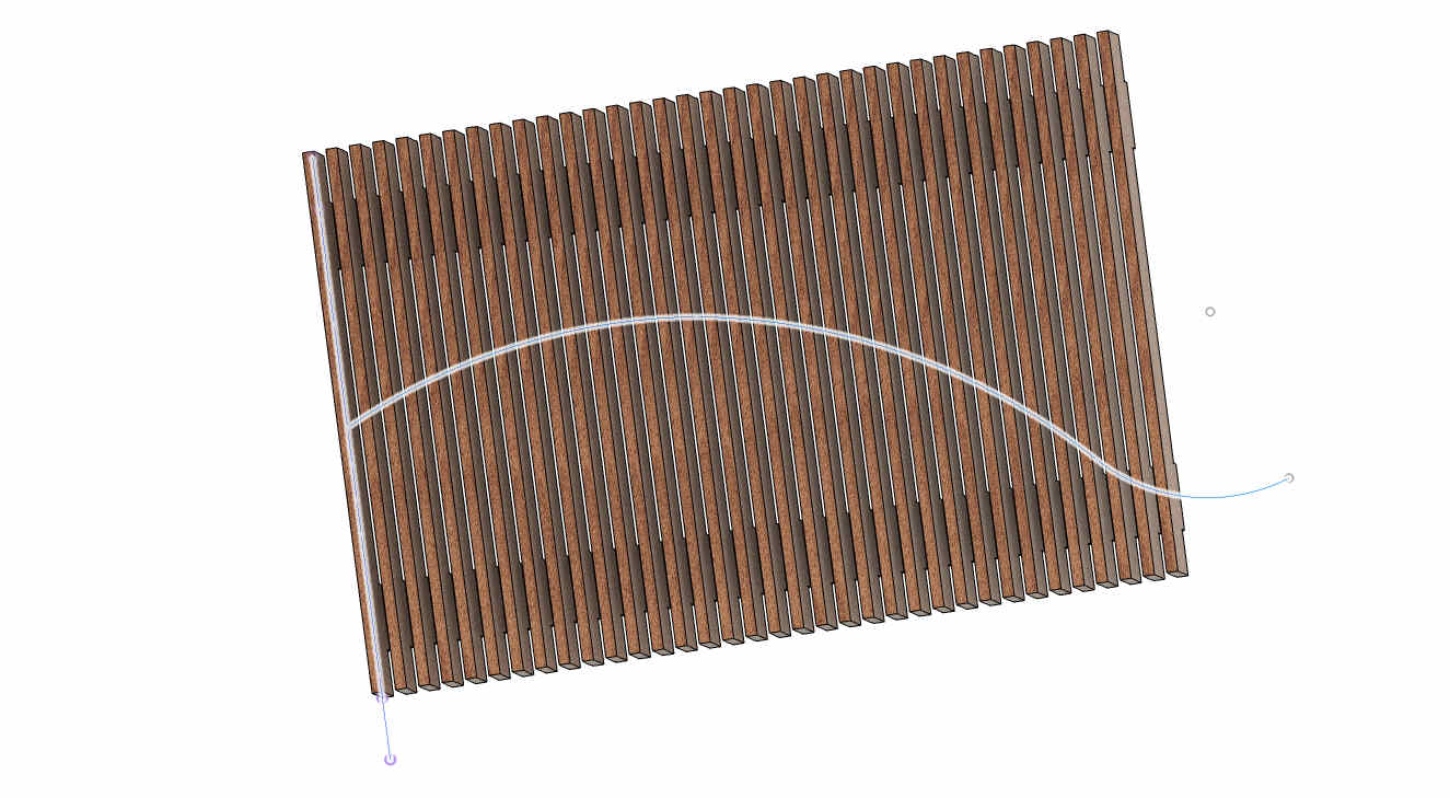
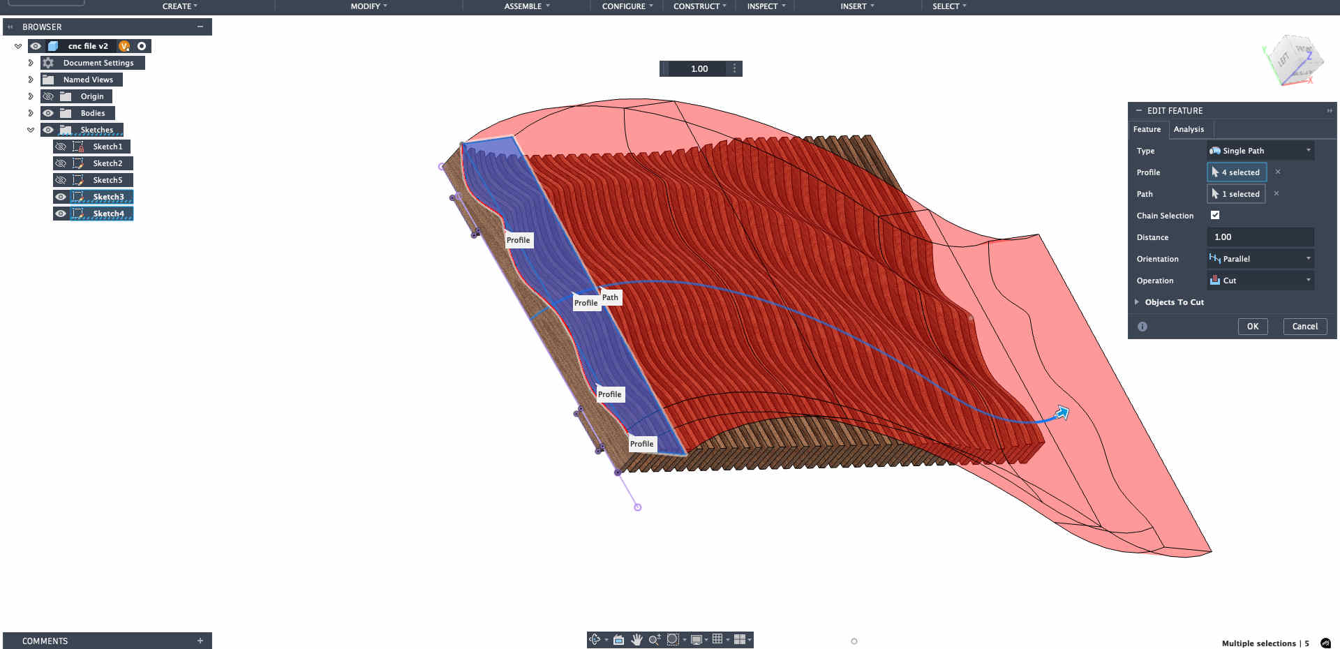
Although I was keen on experimenting, I wanted a back up file ready that I can use if my explorations dont pan out, an easy parametric wave wall was my option
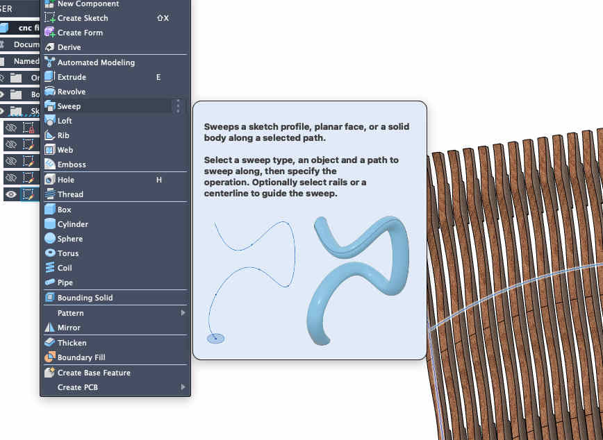
Keeping hands on pause and mind focused on the cut to avoid any mishapsKeeping hands on pause and mind focused on the cut to avoid any mishapsKeeping hands on pause and mind focused on the cut to avoid any mishapsKeeping hands on pause and mind focused on the cut to avoid any mishapsKeeping hands on pause and mind focused on the cut to avoid any mishapsKeeping hands on pause and mind focused on the cut to avoid any mishapsKeeping hands on pause and mind focused on the cut to avoid any mishapsKeeping hands on pause and mind focused on the cut to avoid any mishapsKeeping hands on pause and mind focused on the cut to avoid any mishapsOnce you are done making your required file, fusion has a neat command called arrange, which will help you lay flat all the pieces of your design for manufacturinghttps://www.youtube.com/watch?v=7egLufCg5tk&pp=ygUWYXJyYW5nZSBjb21tYW5kIGZ1c2lvbg%3D%3D
Tutorial for the same.
I created an NC Program for this file ready to cut it if nothing pans out by day 5 of the week
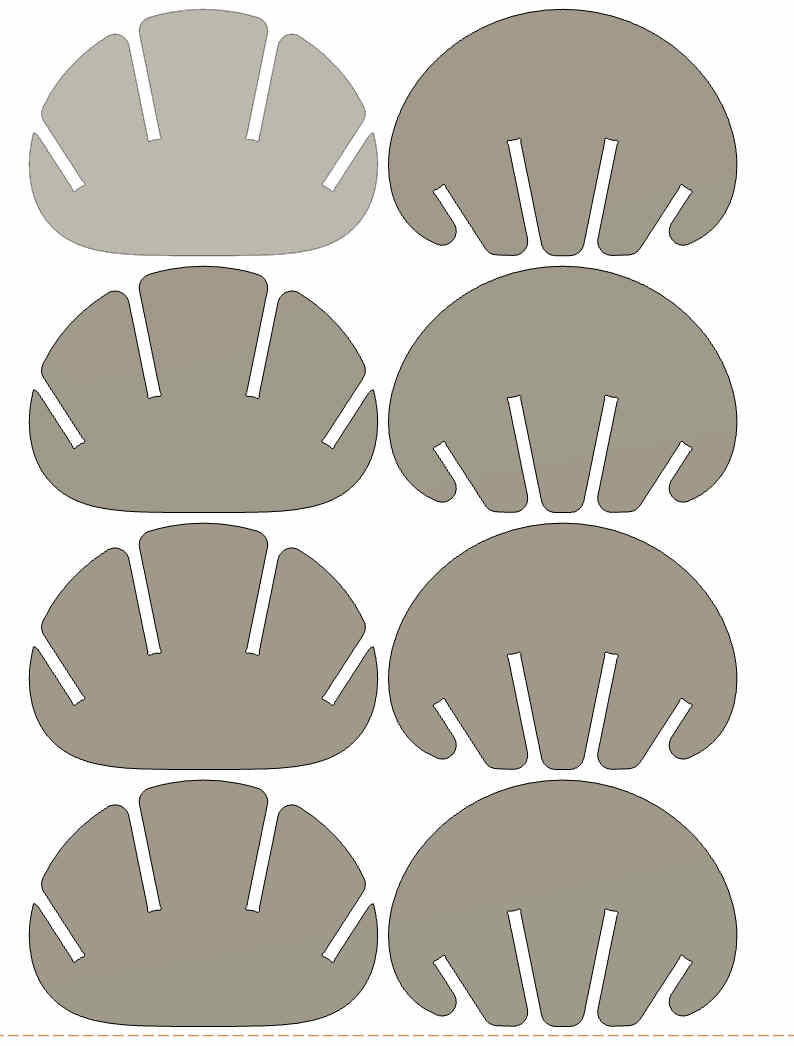
.Final aTorus form!!.
I was sure on waffle structures, but what can i make out of it?
I was sure i cant be the only one to think about waffles
I hoped onto the fab search engine and strted exploring what all is possible
Where i finally stumbled upon
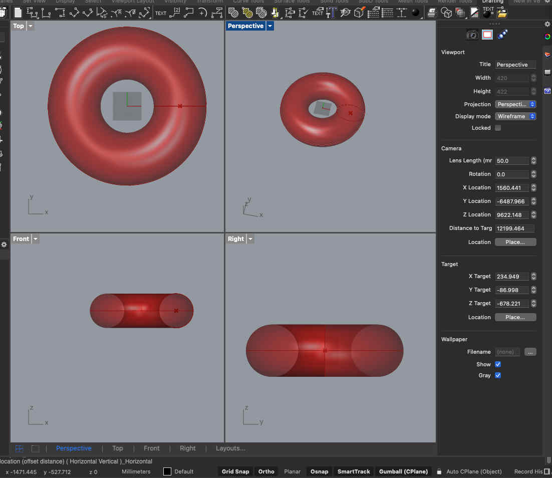
THE aTORUS
It was a super interesting form and I could think of many applications with this form as a base.
While the download files were available, I wanted complete parametric control on the
Angle of intersection
size of each panel
Structure of each panel
So i started watching a few tutorials and researching geometric constraints and created my OWN completly parametric editable version on grasshopper
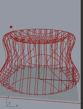
Making the atorus
One geometrical constraint for the atorus is that
the te radiusof the revolved section is R, then the radius of revolve circle should be 2R, only then the form will work
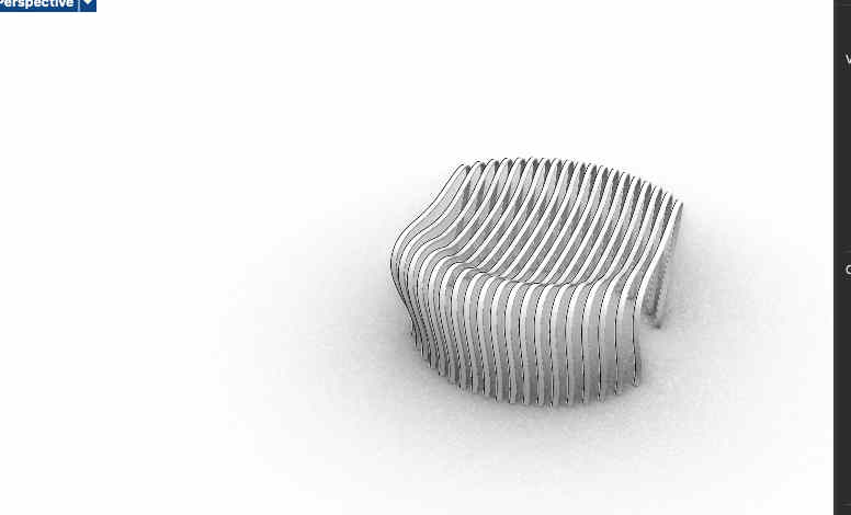
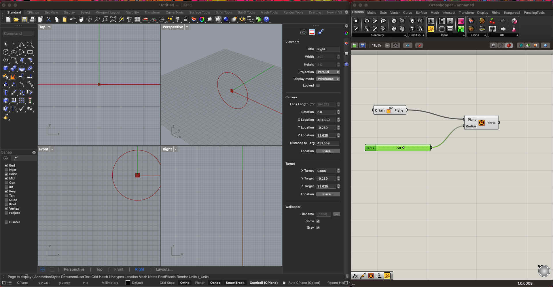
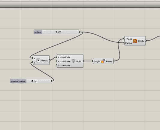
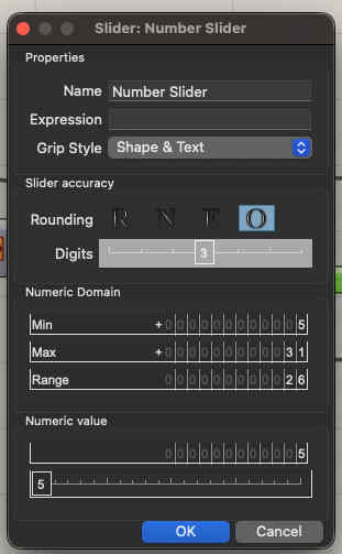
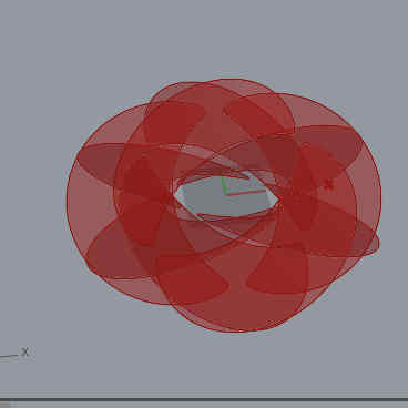
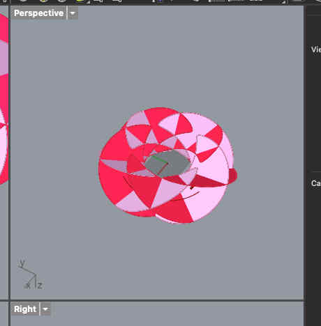
First we create a circle with a radius number slider on the xz planeThen we can use a multiplication module and input A as the radius of circle and 2.01 as input for the revolve circle(B) Now we make a revolved surface with our parameters
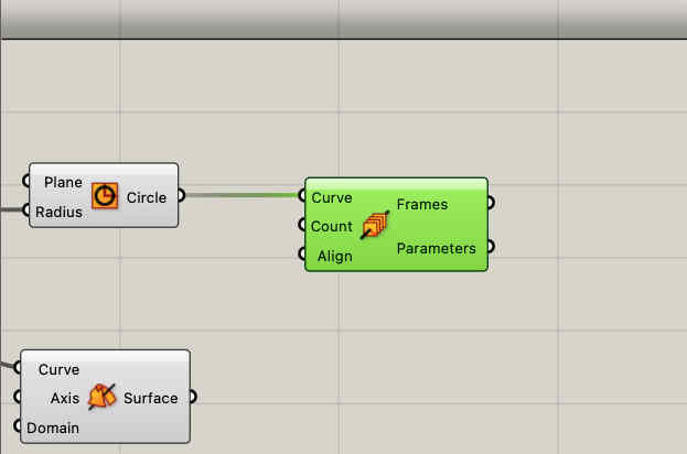
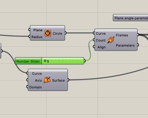
In the same shape you can see i have also divided the shape in frames to use as planes for the waffle structures o be created
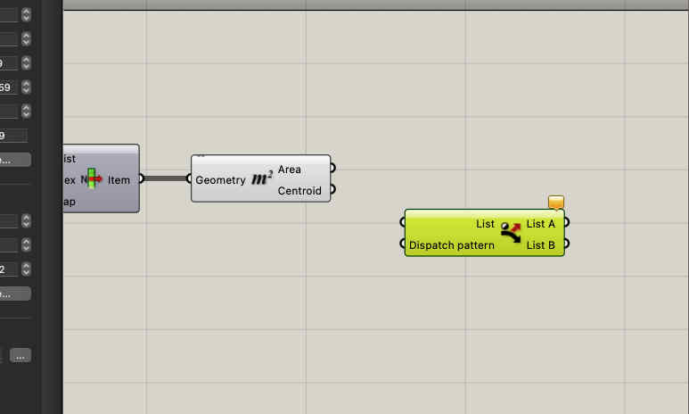
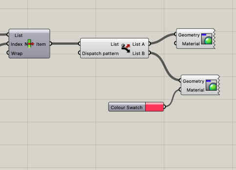
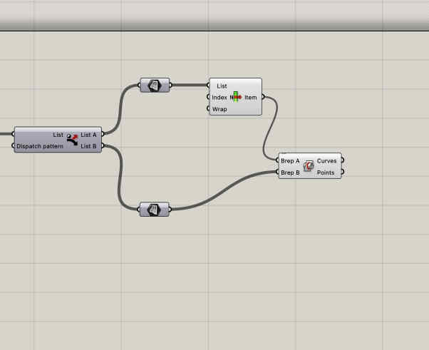
You can add a frame count slider to change the number of frames parametrically Remember to turn the slider parameters to odd, AS ONLY odd number of frames can make this shape With a area and list command you can see how the shapes are now formed on the desired angle of plane we can take our list and with the dispatch command make two sets of lists each consiting of our desired shape To visually see your shape each list can be givena differnt colour so that the form is visible Like so
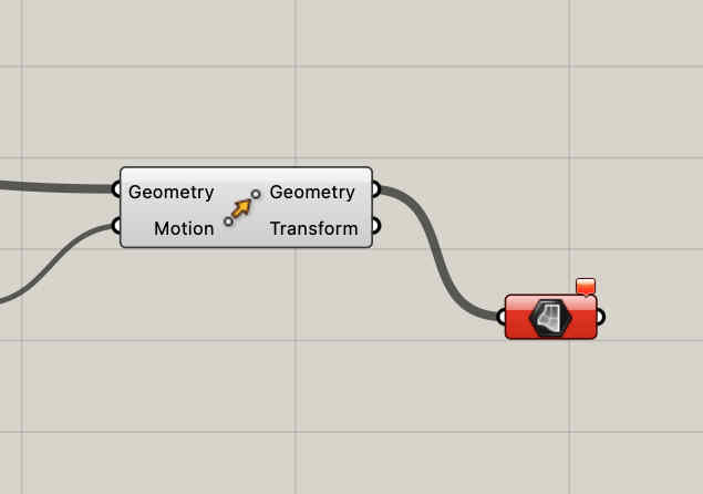
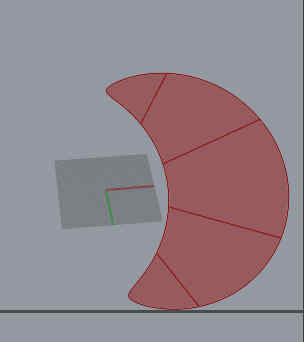
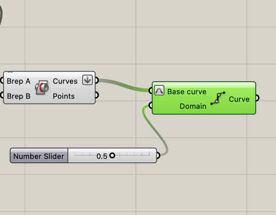
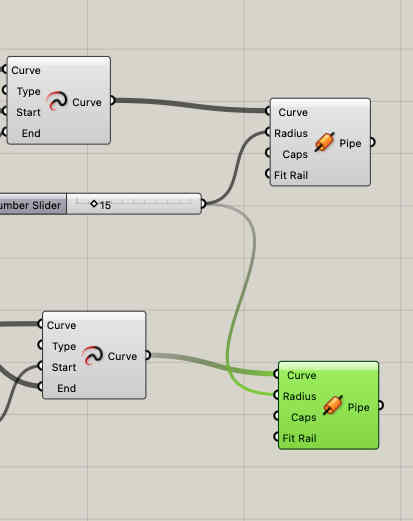
Now that we have the basic shapes we need to figure out half way points of each intersecting paths, to create slots
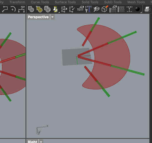
First we find our intersection points Like so Dividing the curves into 2 halves Now we create pipe structures along those lines, the DIAMETER of the pipe becomes our slot width
you can create one, then just cpy paste and change input geometry
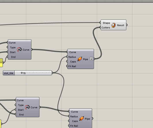
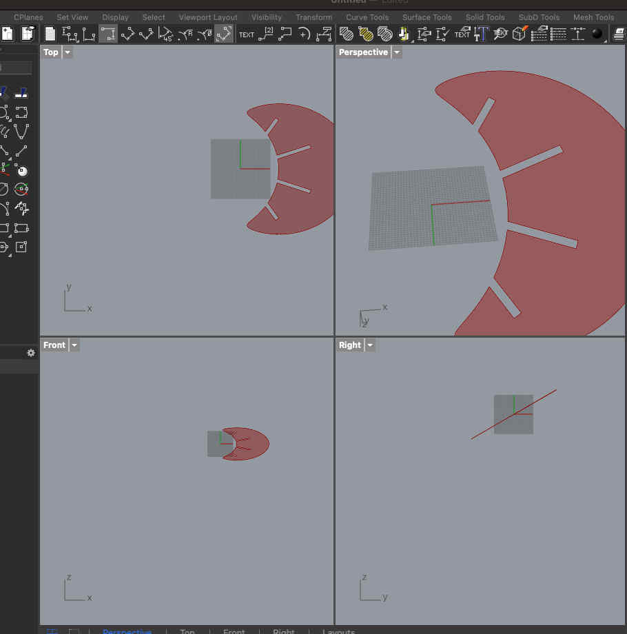
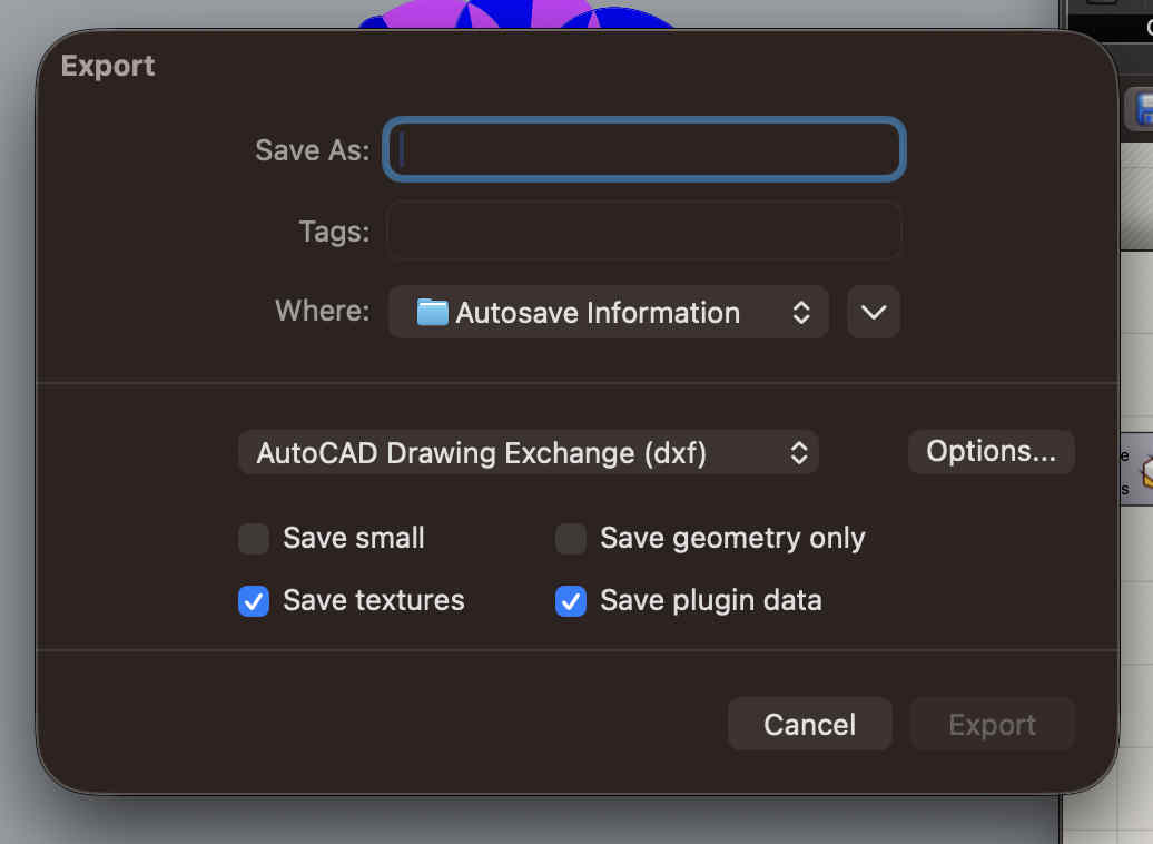
Extend the pipe further so that no slot is left uncut Use a body trim command VOILAAAA Bake the surface and export dxf to make nc file and edits to make assembly easy Import to fusion create dogbones as described earlier
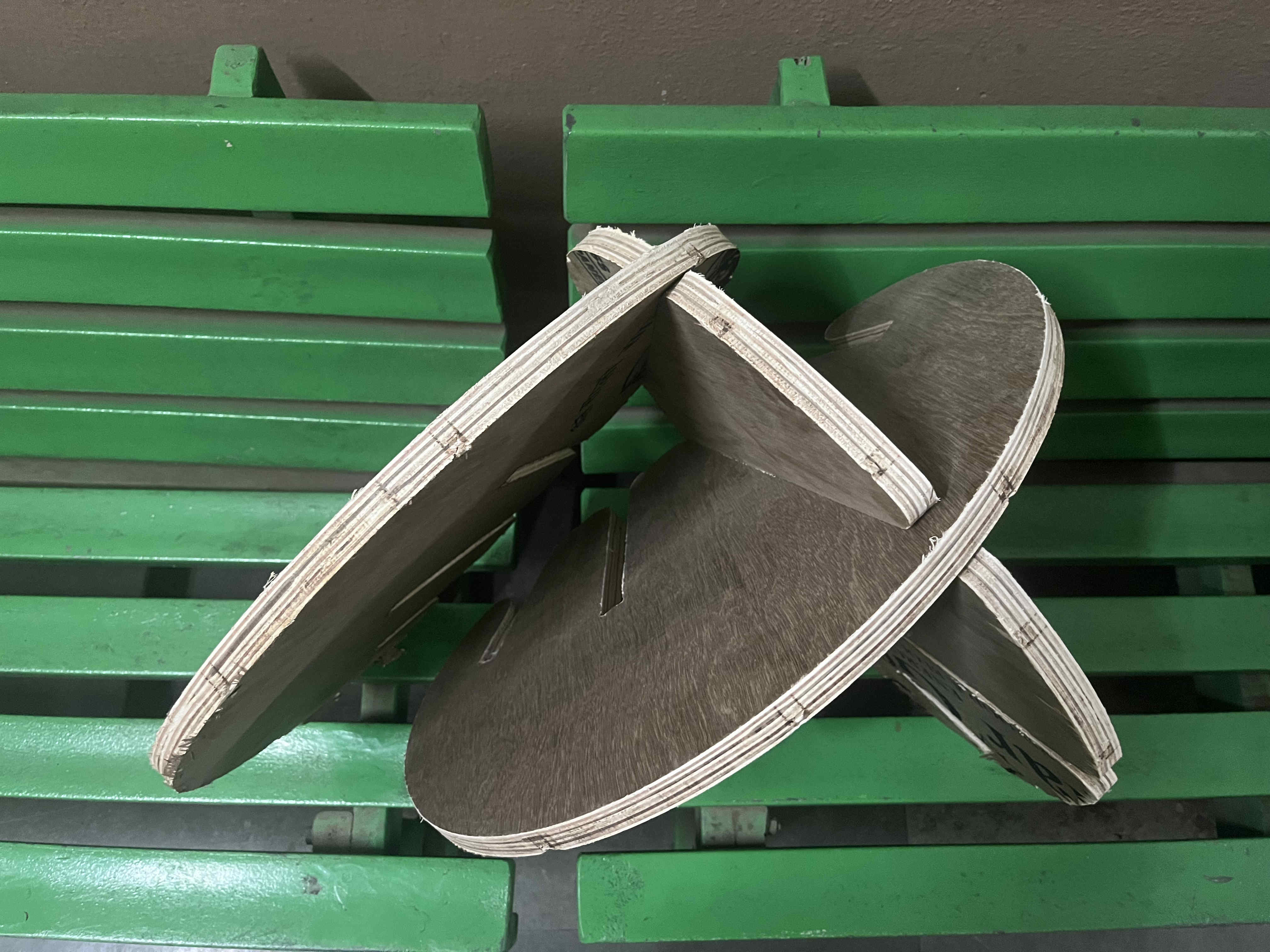
Test
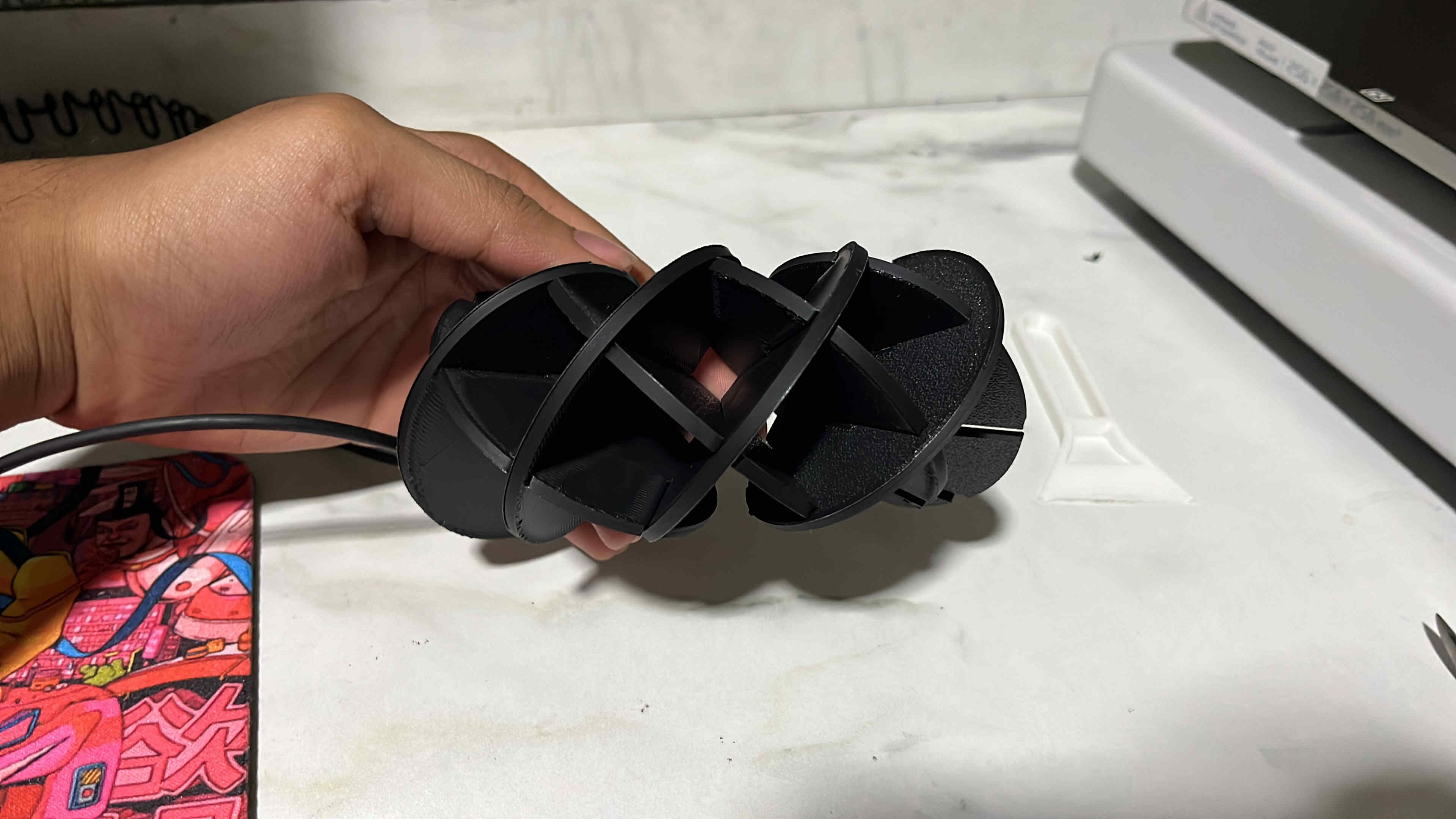
I tested a smaller format by 3d prinitng it, and it was assebling wellI chose to 3d print as a laser cutter was not available, although any cnc proto is best to be made on laser cutter
Create NC program and machine setup as described earlier
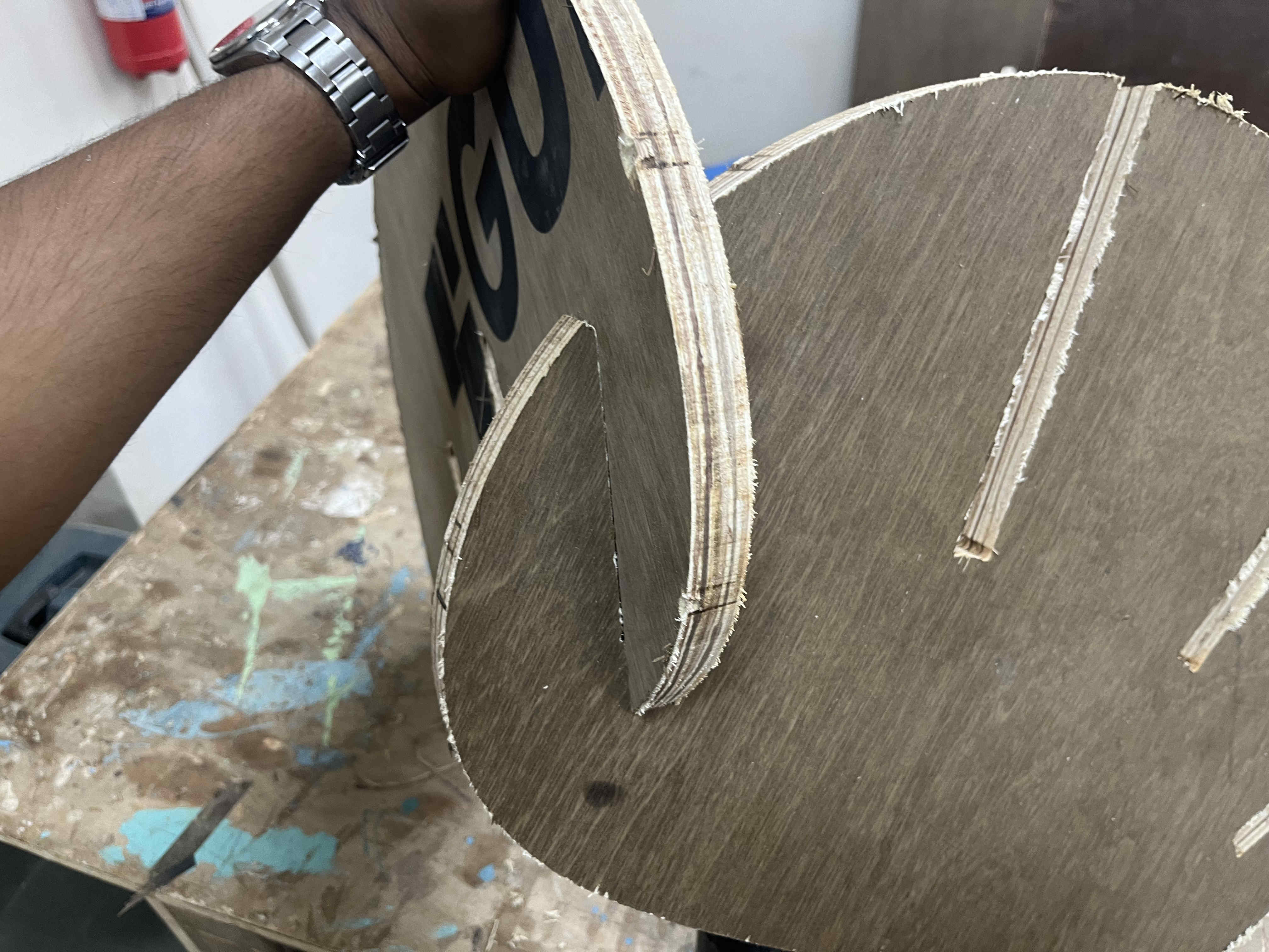
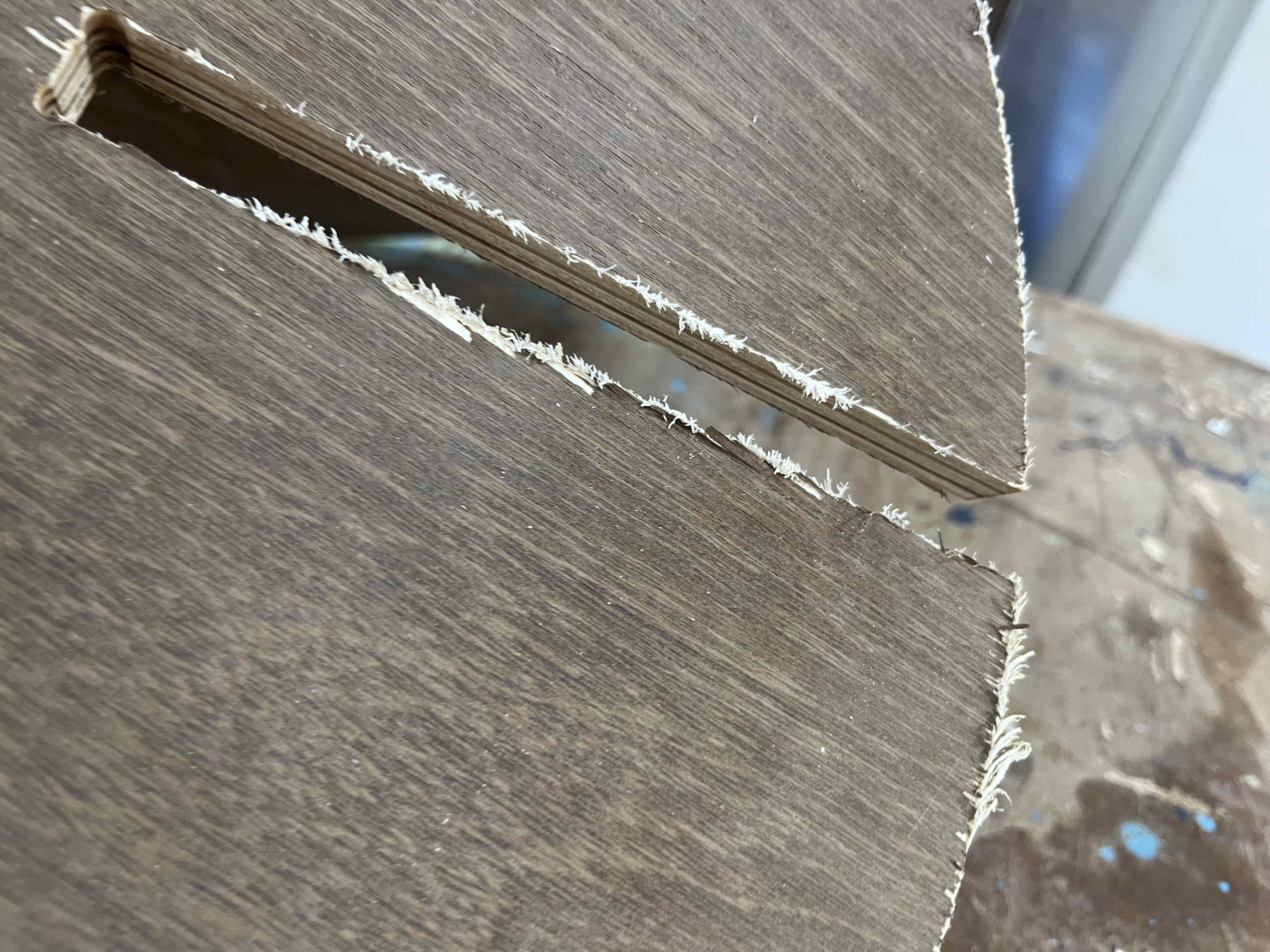
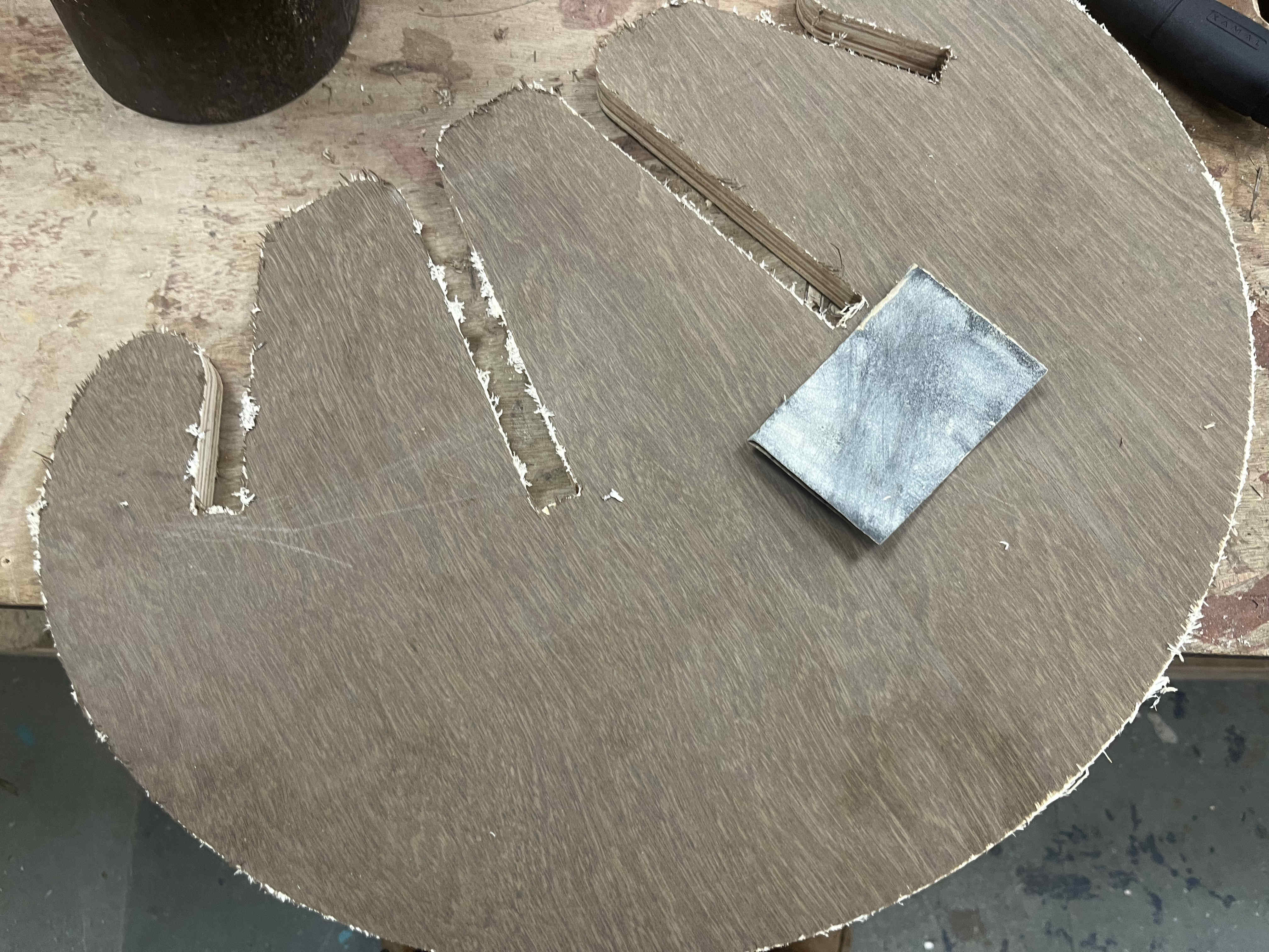
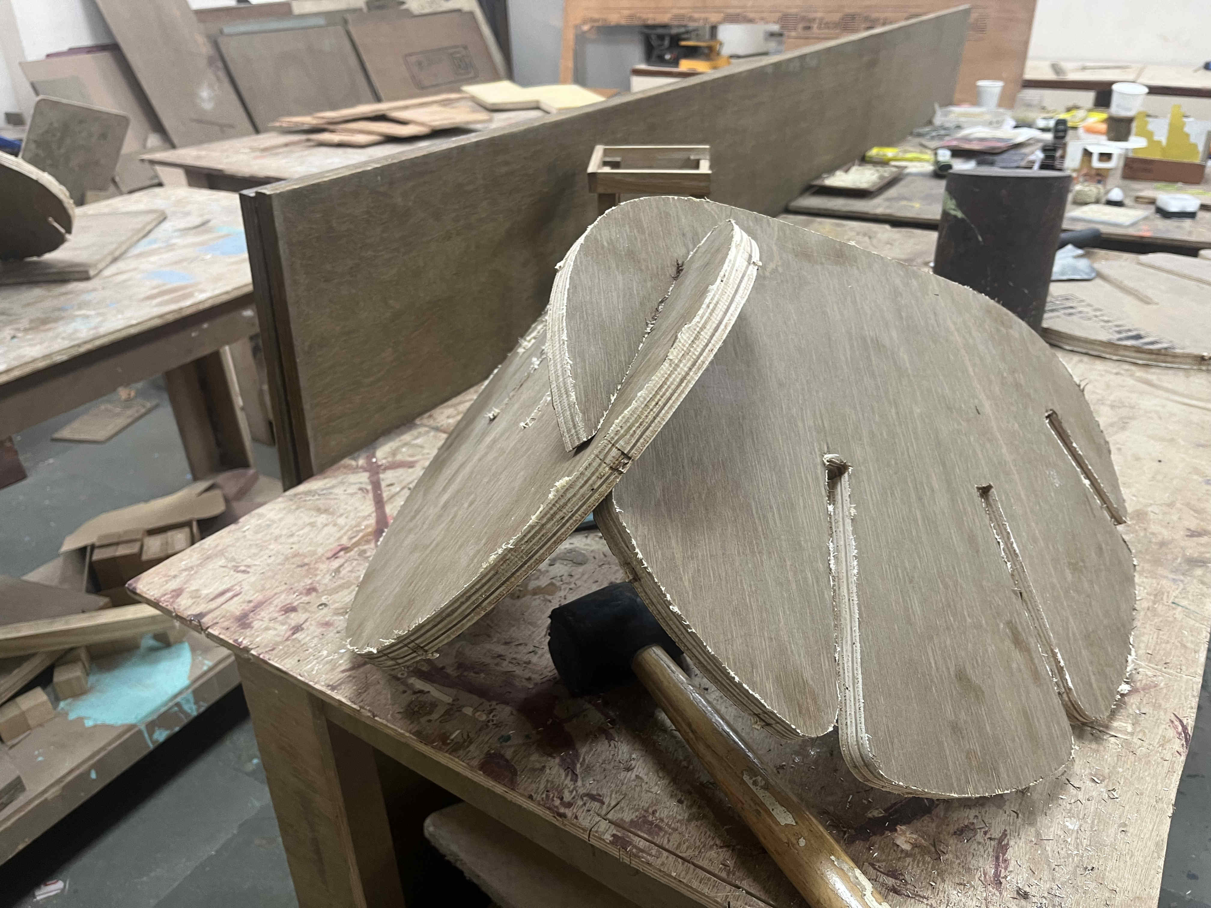
cuttin the file after setting xy and z co ordinates The bit did not go all the way through thus we had to hammer and chisel the piece out The pieces came out fine but the tolerance was toooo tight, a tolerance of .35 was given Straight 90 degree edges made slot ends made putting them together super hard as well
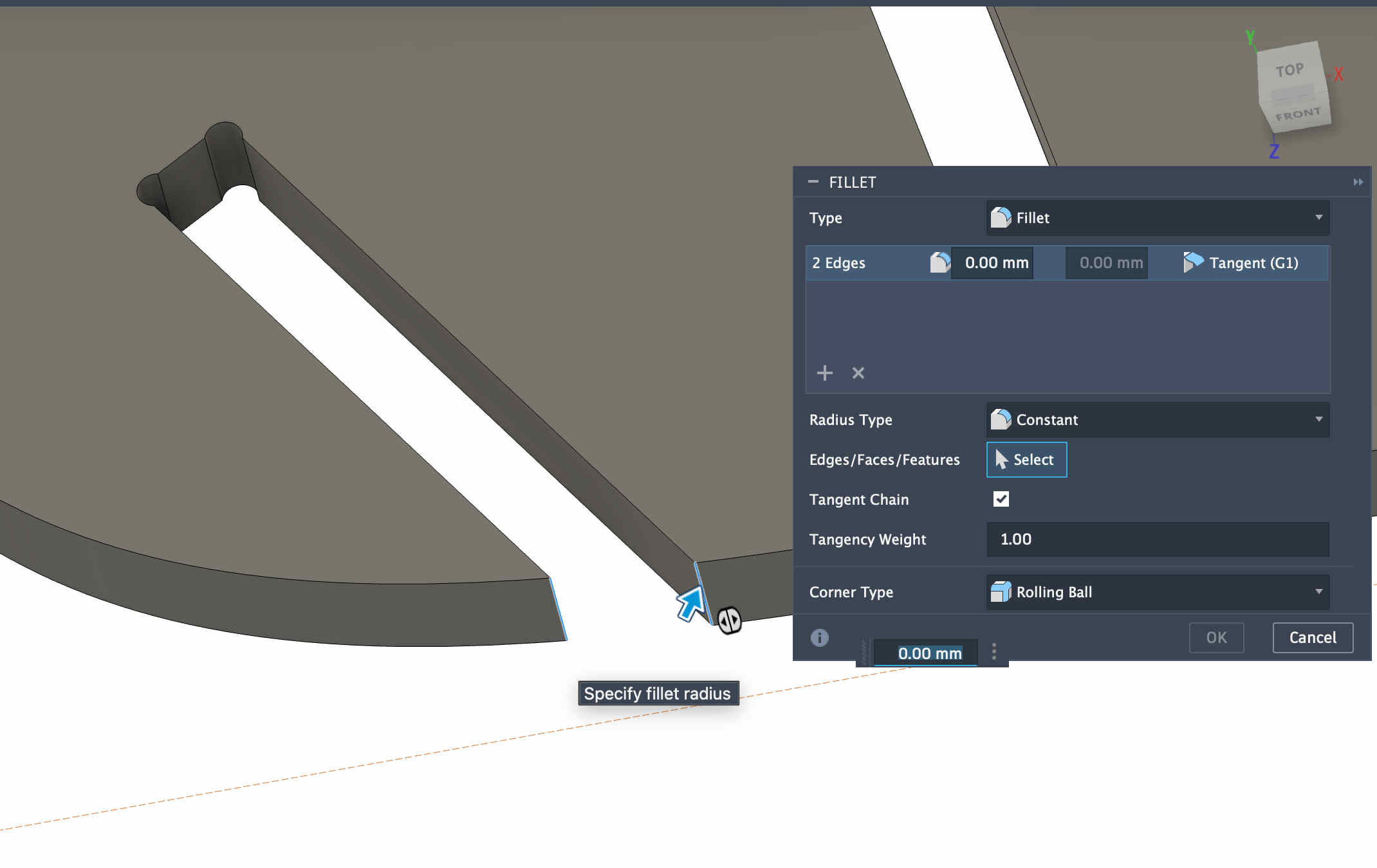
With the info that I acquired I edited the file with new tolarence and fillets
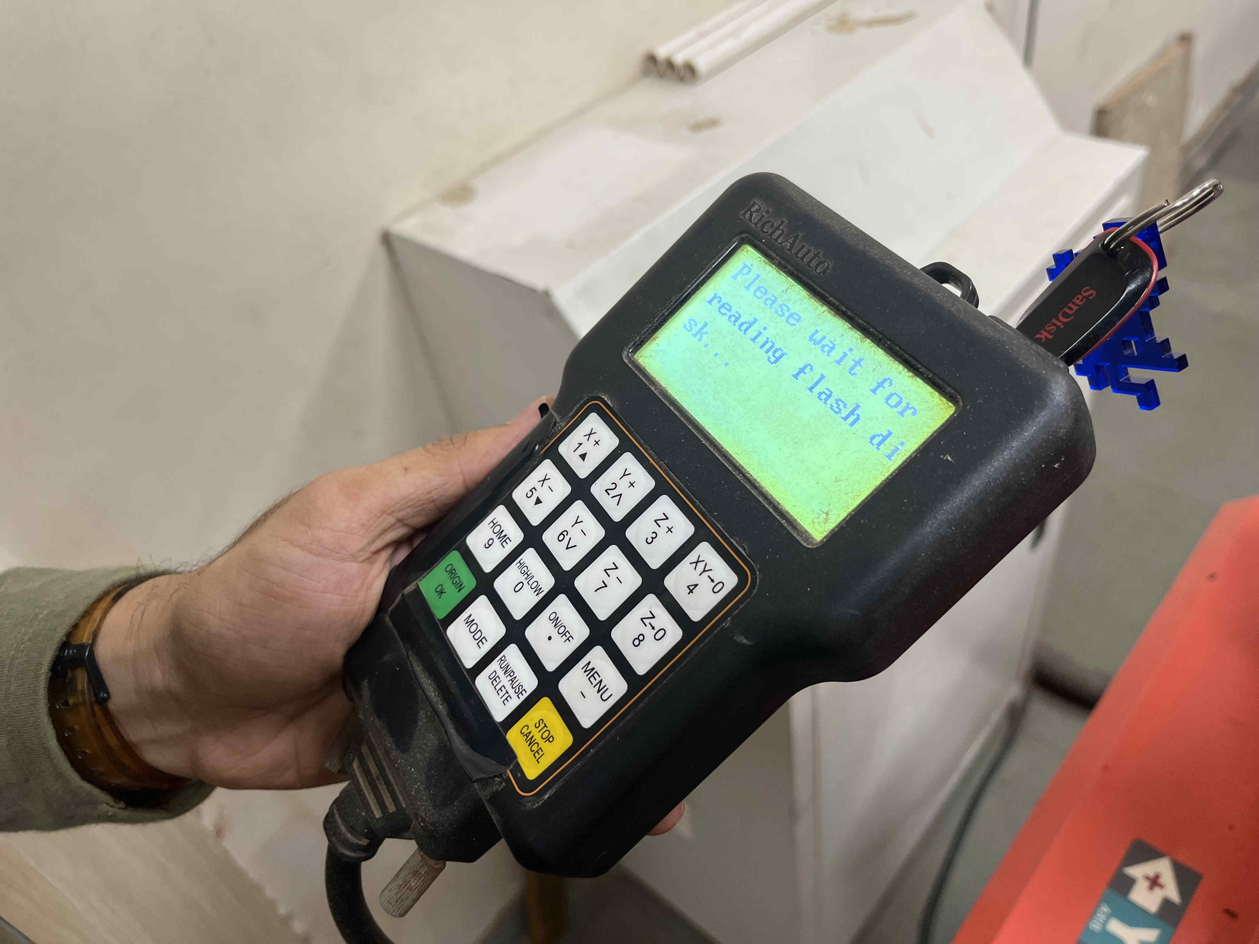
The pieces came out fine but the tolerance was toooo tight, a tolerance of .35 was givenChanging design doesnt mean changed NC file contours, youll need to reinput Geometry as well New file.posting file to driveRichauto controller not reading flash drive:/
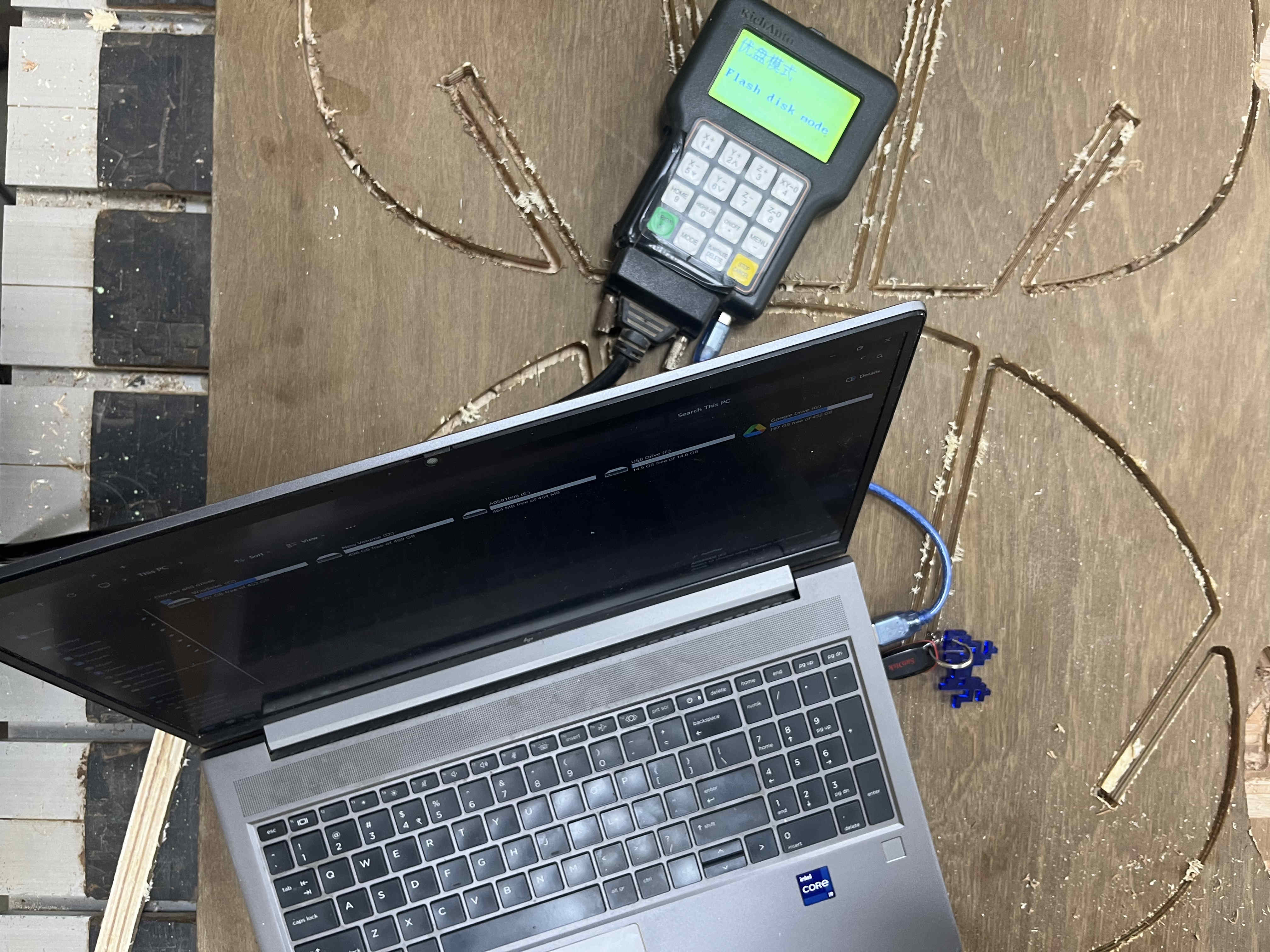
My controller stopped reading the pen drives that were inserted
while trying multiple ports i noticed another data port on the bottom of the controller, port was similar to that of an old arduino uno
Connecting laptop directly to the controllerFor this you need to connect the controller in flash disk mode where you can upload the file manually and then power on the machine
WE CAN CUT NOW LETS GOOOOO
When the machine is done WE ARE NOT
Sanding it down
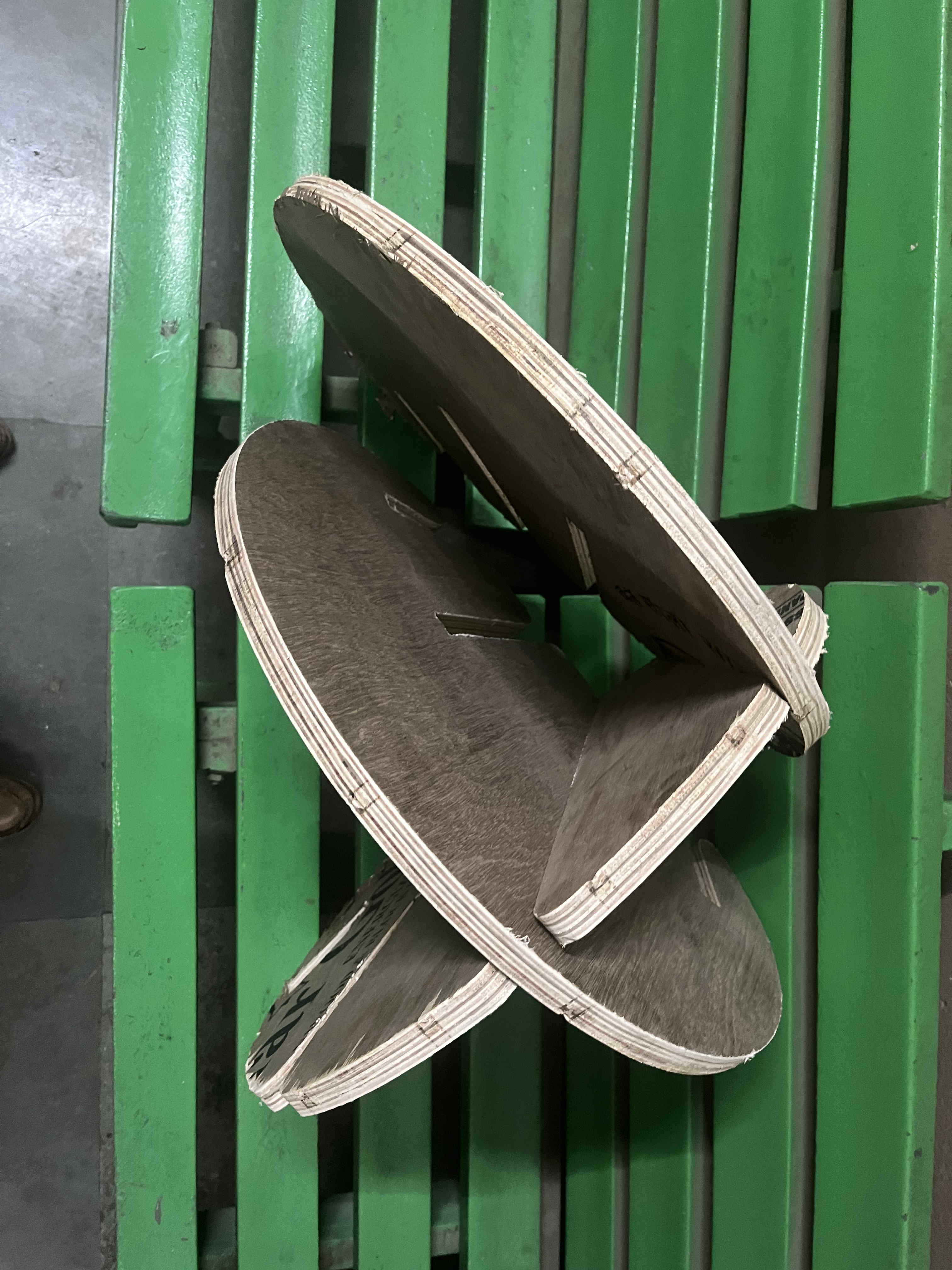
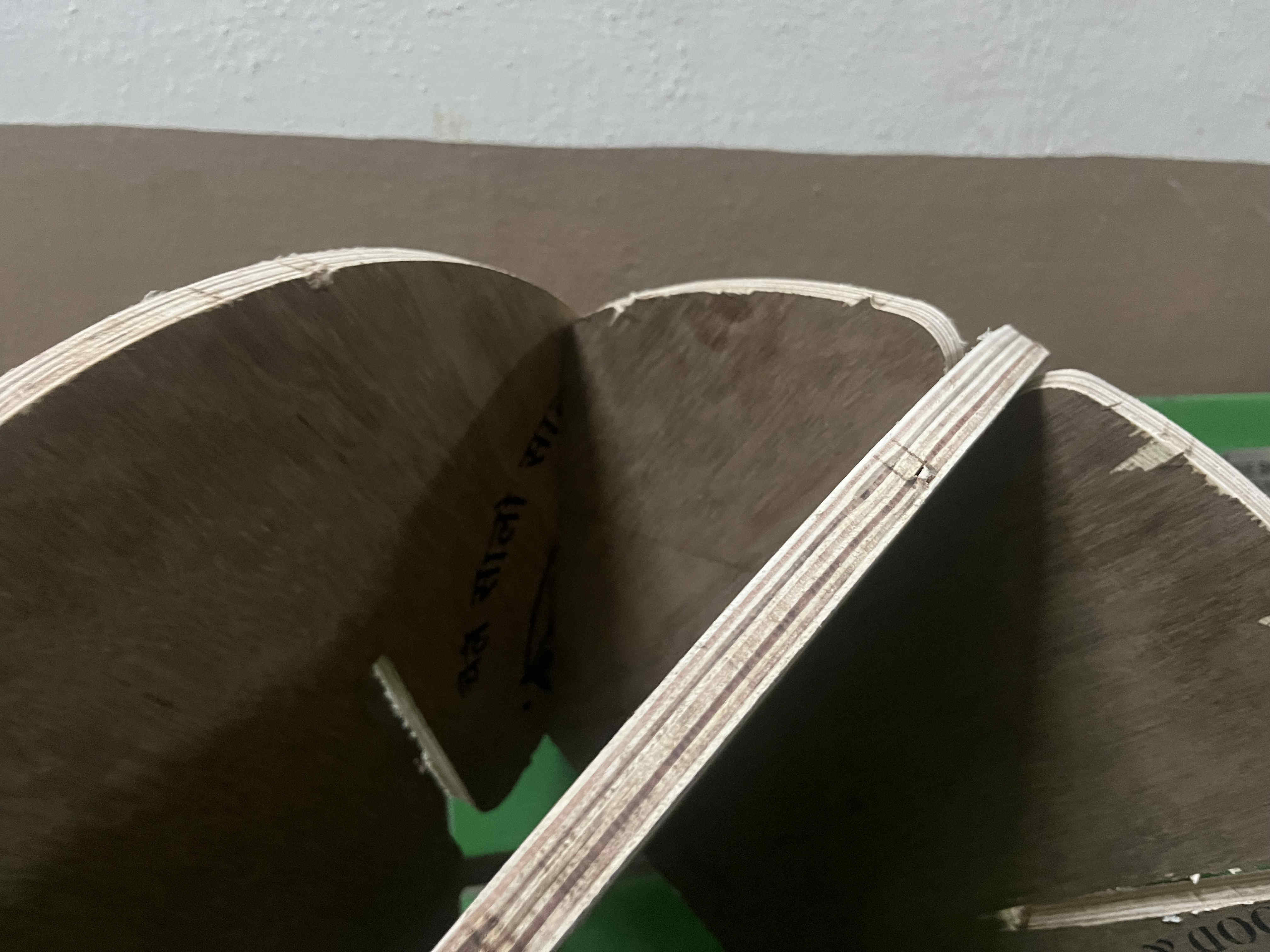
Better fits but still very tight for this designThis is how it sold look like once assembled.
I faced a couple of issues while machining
The machining time for 22 pieces was quite long and the cnc lab was busy
There was limited 12mm plys which i had designed for
while machining, a bolt on the spindle houaing came loose and fell on the y axis track. causing the machine to snag and stall. it is only after a week when we figured out the problem.
Thus I lost some time and moved on to the next week, the files are ready only need to be cut which ill surely explore in my freetime.