.Netwroking & communications.
Networking & Communication in Embedded Systems
Networking and communication allow embedded devices to share data with sensors, displays, and other microcontrollers. Instead of working alone, devices can communicate over protocols like I²C, SPI, UART, and CAN to build more complex systems.
I²C Communication: SDA & SCL Pins
I²C (Inter-Integrated Circuit) is a two-wire communication protocol widely used in embedded programming. It uses:
- SDA (Serial Data) – Transfers data between devices
- SCL (Serial Clock) – Synchronizes communication using a clock signal
Multiple devices can share the same SDA and SCL lines, each with a unique address. This makes I²C efficient for connecting many peripherals using only two pins.
Applications
- Connecting sensors (temperature, IMU, distance sensors)
- Display modules (OLED, LCD)
- Real-Time Clock (RTC) modules
- Communication between multiple microcontrollers
- IO expanders to increase GPIO pins
For this weeks exploration i tried a couple variations
RP2040 - ESP WROOM 32
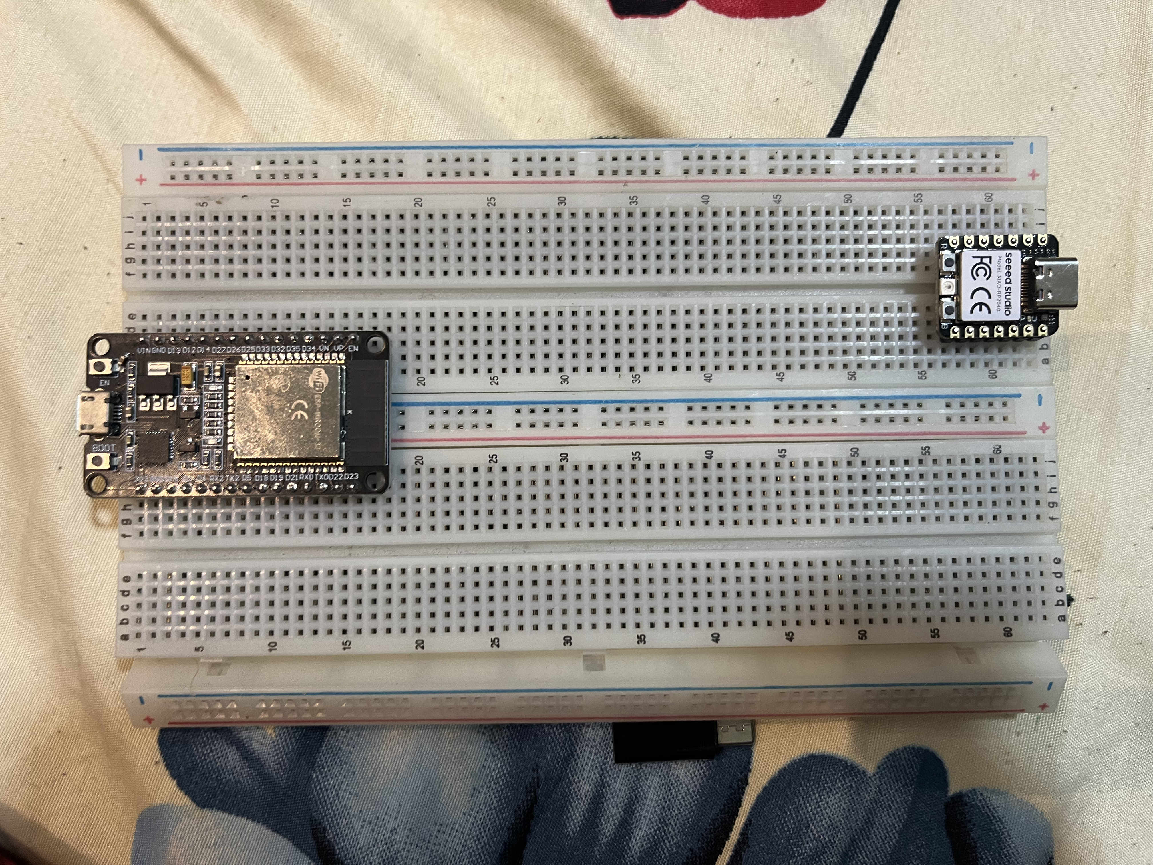
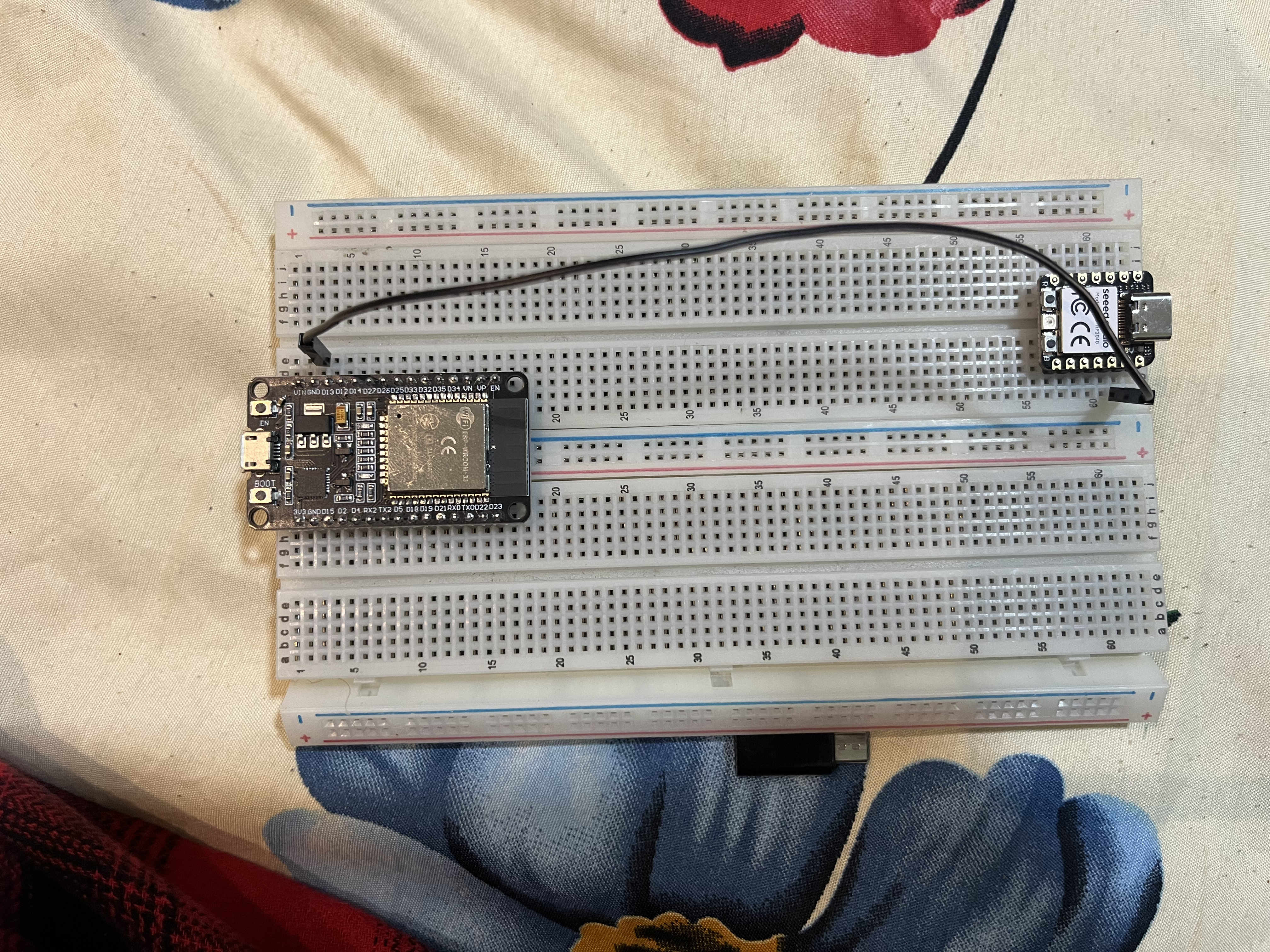
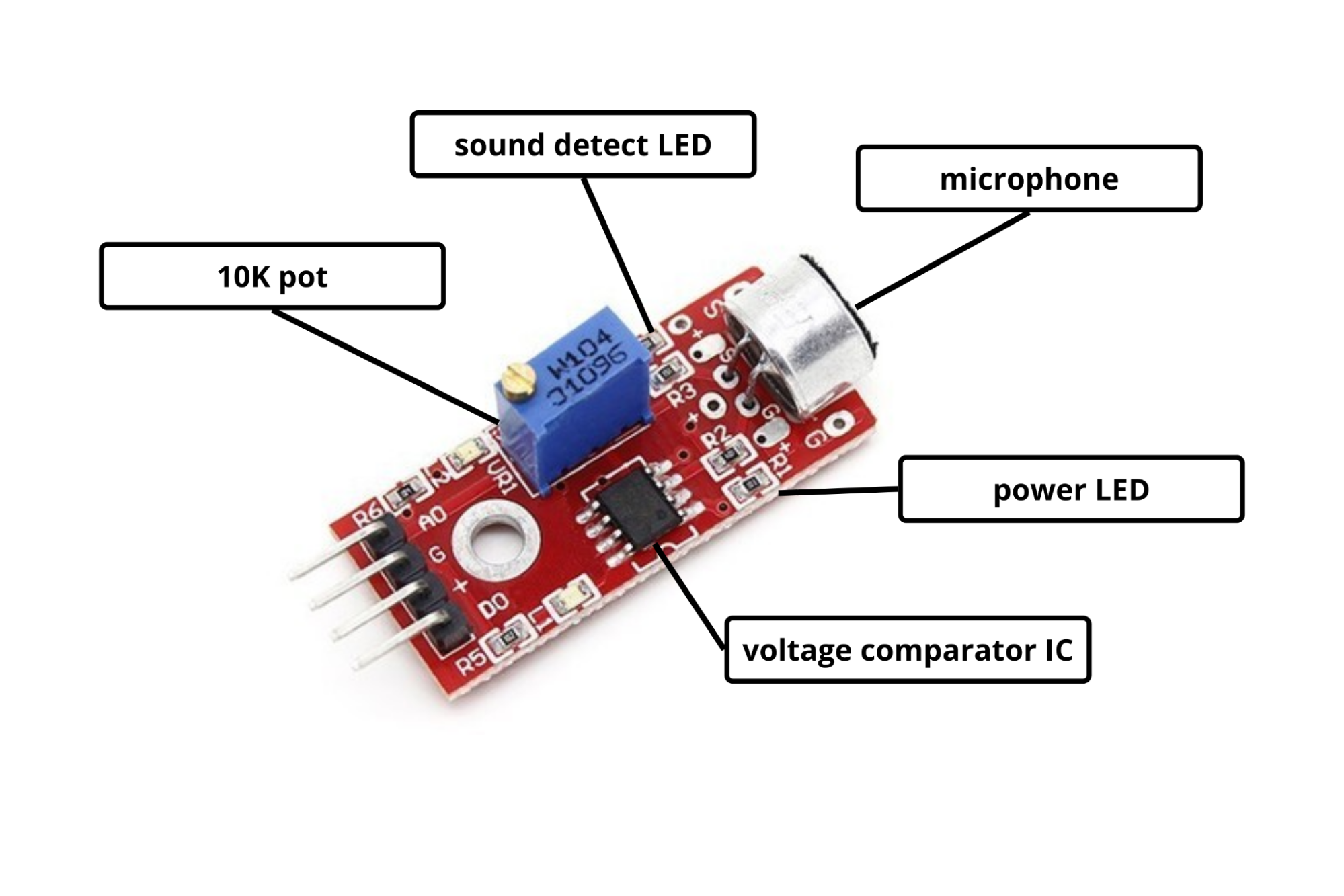
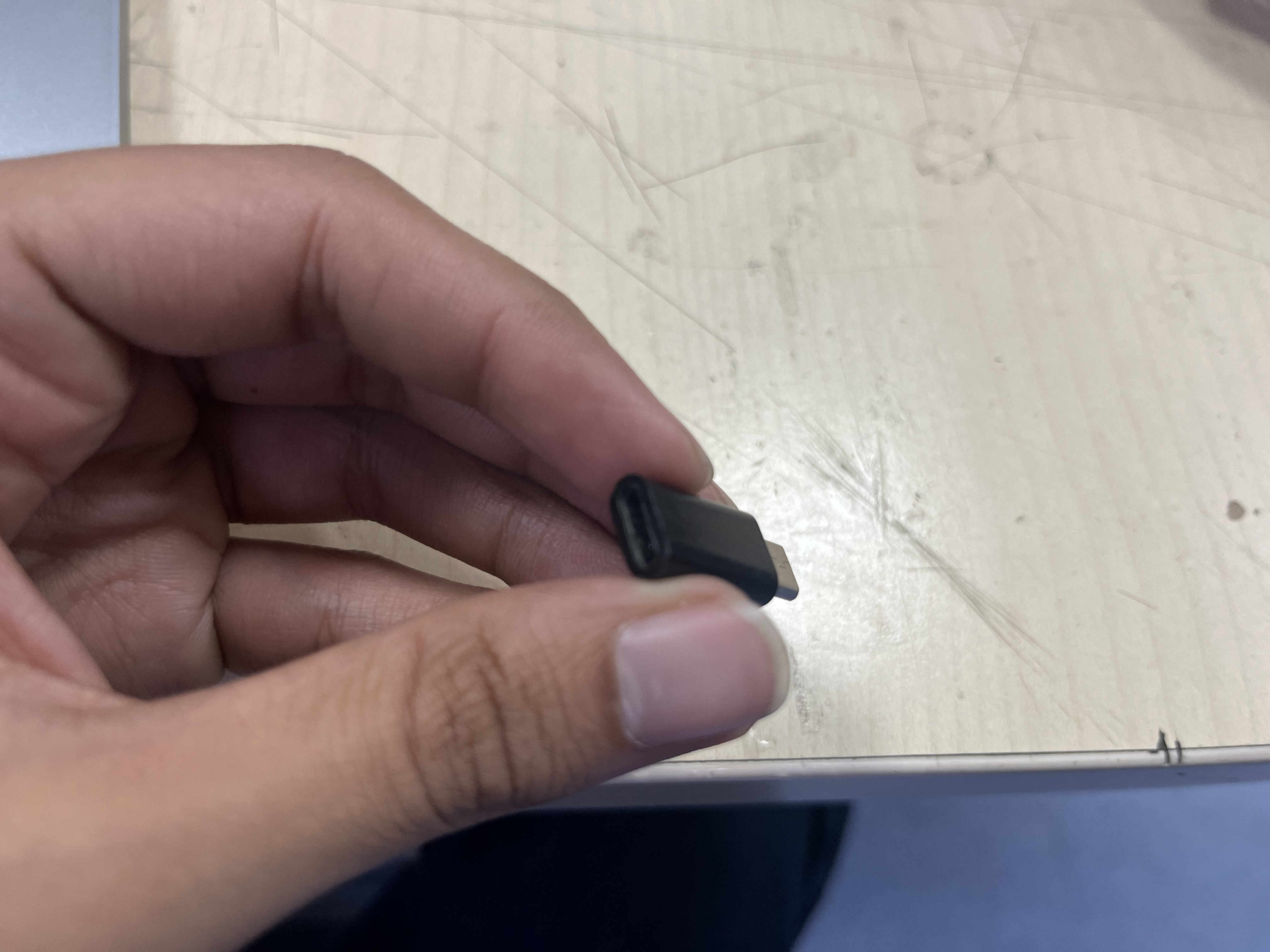
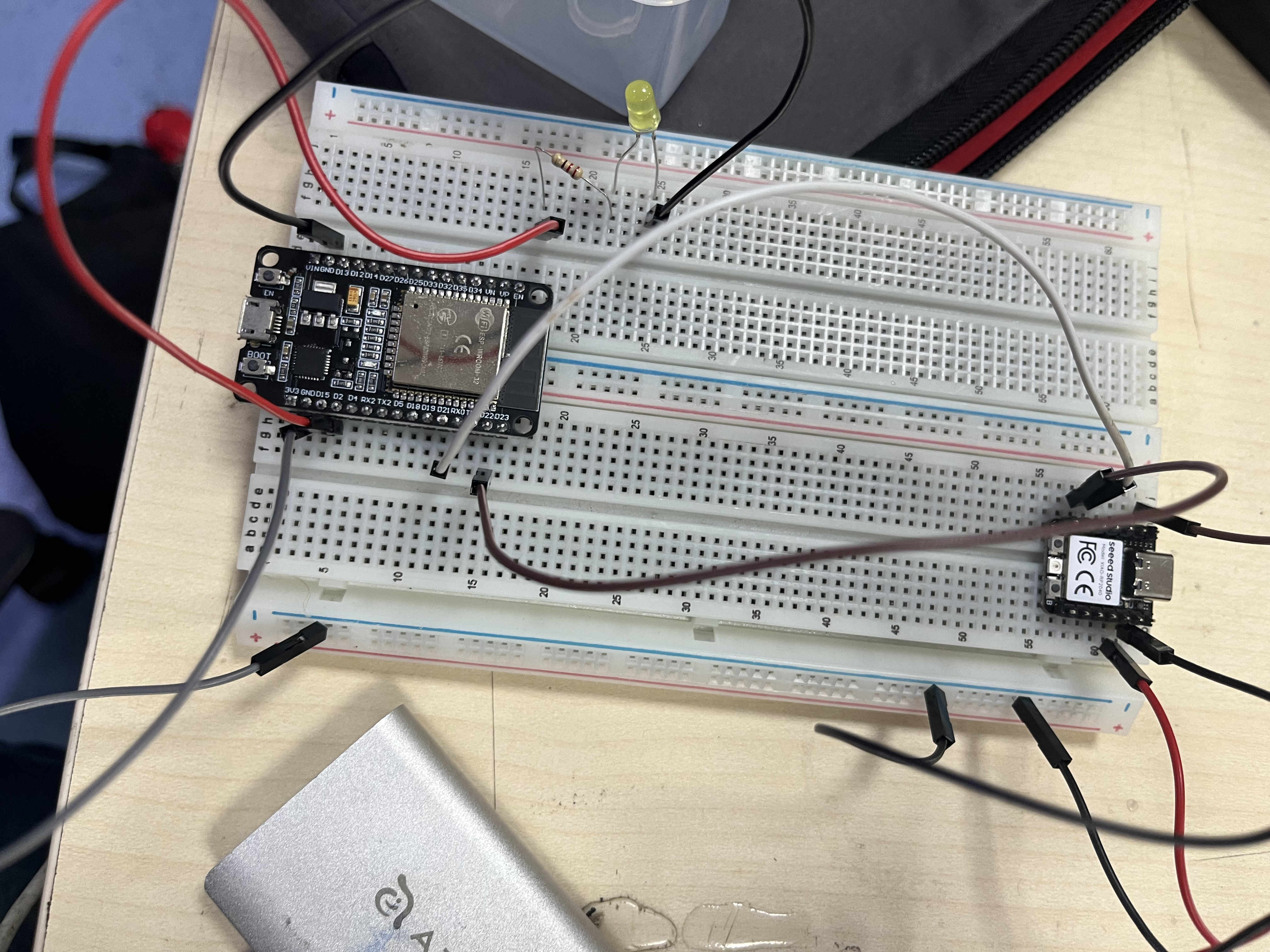
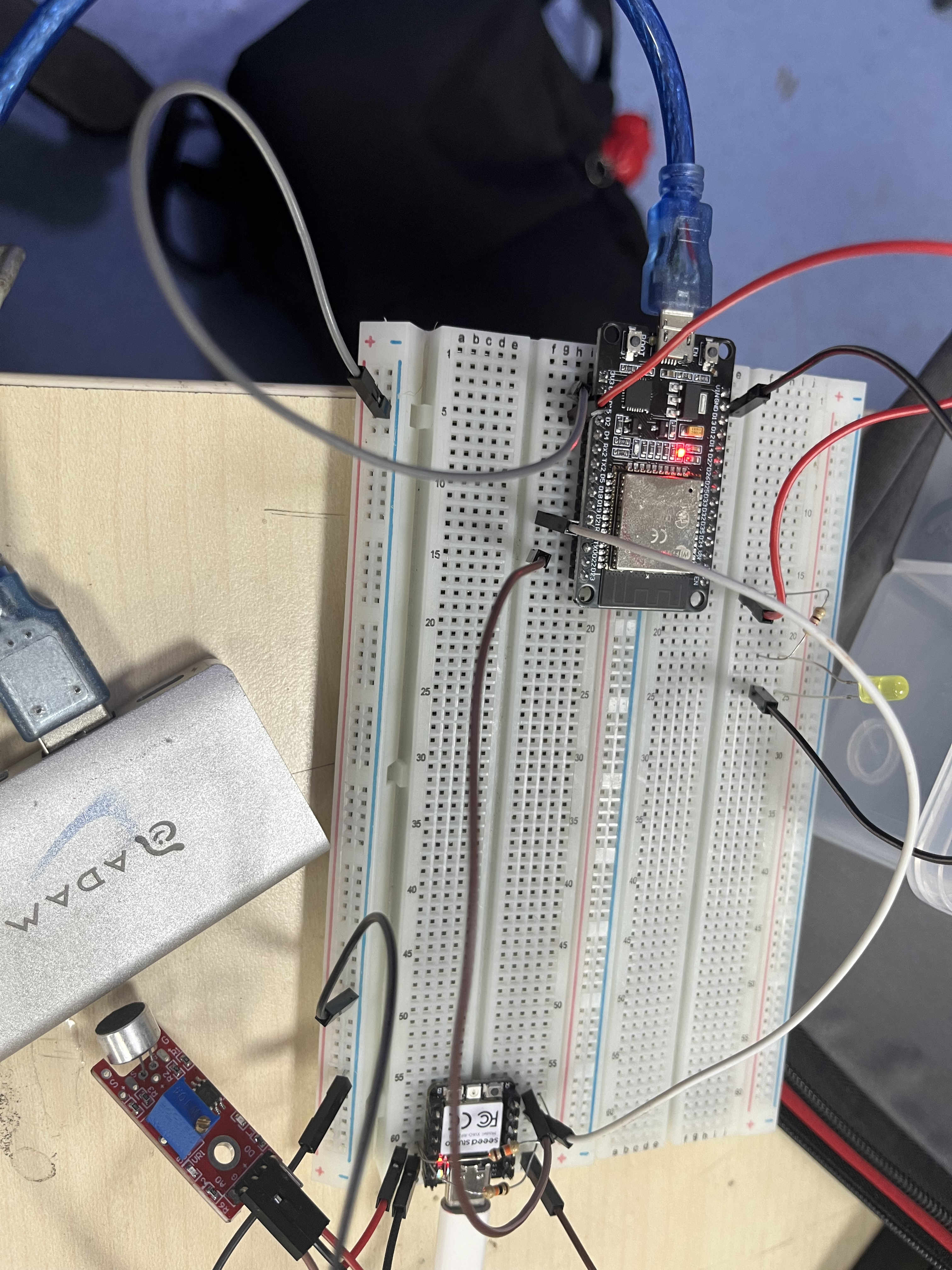


Here is the code to be uploaded to master
  void setup() {
  Serial.begin(115200);
}

void loop() {
  int minVal = 4095, maxVal = 0;

  // Sample for 200ms
  unsigned long start = millis();
  while (millis() - start < 200) {
    int val = analogRead(A0);
    if (val < minVal) minVal = val;
    if (val > maxVal) maxVal = val;
  }

  Serial.print("Min: "); Serial.print(minVal);
  Serial.print("  Max: "); Serial.print(maxVal);
  Serial.print("  Range: "); Serial.println(maxVal - minVal);
  delay(100);
}
.ESP to Laptop.
Connecting esp to lapyop via wifi using espnow
For my final project I also needed an external device to send data, I decided to explore that here.

This is crucial to increase the range.
#include
#include
#include

// Your WiFi credentials
const char* ssid = "Scarlett";
const char* password = "Scarlett$123";

#define LED_PIN D0
#define NUM_LEDS 42

Adafruit_NeoPixel strip(NUM_LEDS, LED_PIN, NEO_GRB + NEO_KHZ800);
WebSocketsServer webSocket = WebSocketsServer(81);

void onWebSocketEvent(uint8_t client, WStype_t type, uint8_t* payload, size_t length) {
  if (type == WStype_BIN && length == NUM_LEDS * 3) {
    // Received 126 bytes — one RGB value per LED
    for (int i = 0; i < NUM_LEDS; i++) {
      uint8_t r = payload[i * 3];
      uint8_t g = payload[i * 3 + 1];
      uint8_t b = payload[i * 3 + 2];
      strip.setPixelColor(i, strip.Color(r, g, b));
    }
    strip.show();
  }
}
Upload this code on the baord.
Networking redo
For the redo i decided to do a basic exploration to establish connections between 2 boards
ESP-32-S3 & ESP 8266
I am using the same board as my final project, the gerber files and more can be found in the download section here
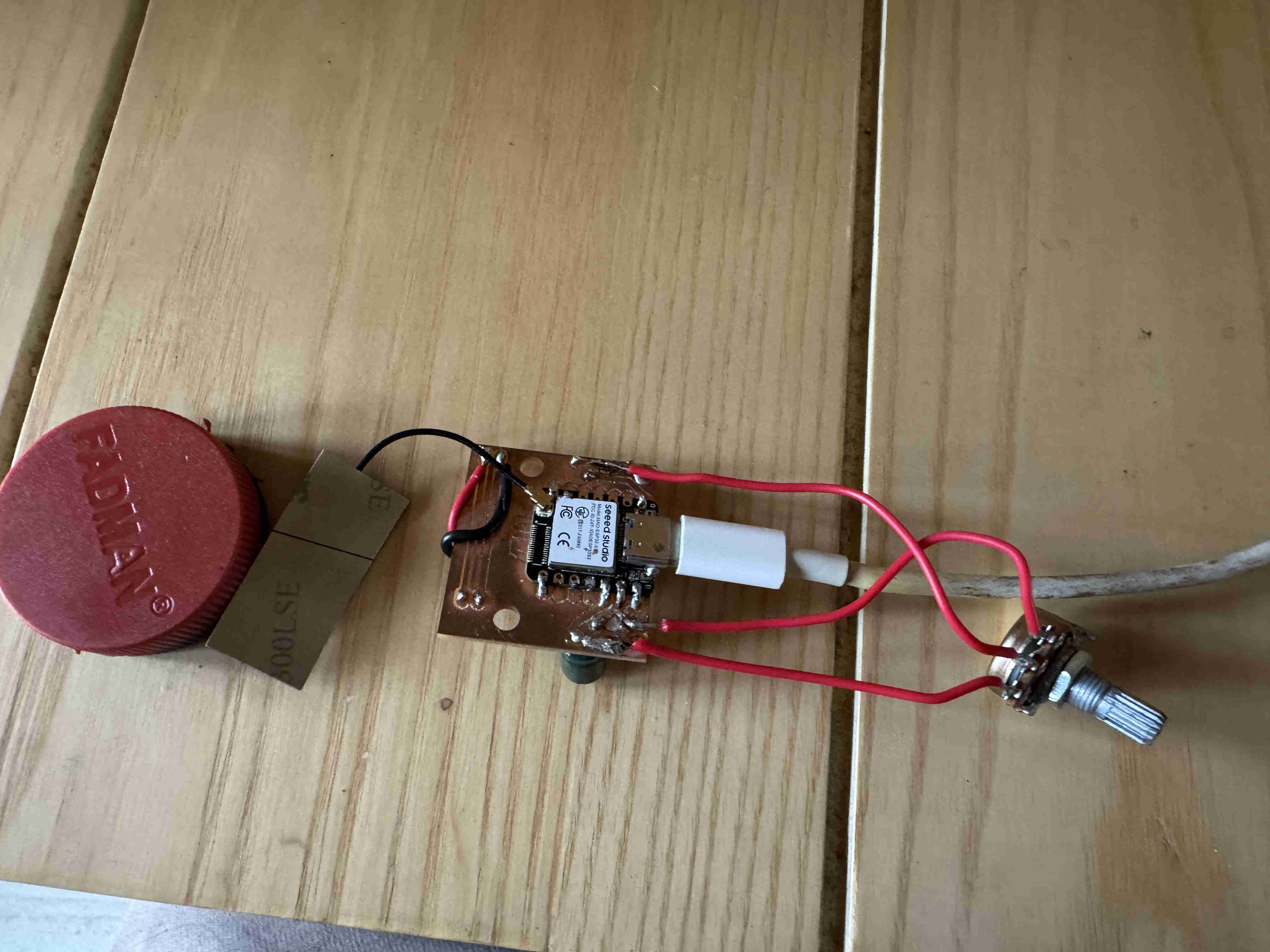
I wired the POT meter again just as in Input devices
1.
#include

void setup() {
  Serial.begin(115200);
  delay(500);
  Serial.println();
  Serial.print("ESP8266 MAC Address: ");
  Serial.println(WiFi.macAddress());
}

void loop() {}
Flash this code to the ESP8266 to retrive mac address. Open terminal and sync bnaud lengths and youll recieve the mac address
#include

void setup() {
  Serial.begin(115200);
  delay(500);
  WiFi.mode(WIFI_STA);
  Serial.println();
  Serial.print("ESP32-S3 MAC Address: ");
  Serial.println(WiFi.macAddress());
}

void loop() {}
Same fucntion code for the s3 in case you need bi-directinal networking.

wire the board as such if you are following along.
2.
#include
#include

// ← Replace with YOUR ESP8266's MAC address from Step 1
uint8_t receiverMac[] = {};

#define POT_PIN  1   // D0 on XIAO ESP32-S3 = GPIO1

typedef struct {
  int potValue;
} DataPacket;

DataPacket packet;

void onSent(const uint8_t *mac, esp_now_send_status_t status) {
  Serial.print("Send status: ");
  Serial.println(status == ESP_NOW_SEND_SUCCESS ? "OK" : "FAIL");
}

void setup() {
  Serial.begin(115200);
  WiFi.mode(WIFI_STA);

  if (esp_now_init() != ESP_OK) {
    Serial.println("ESP-NOW init failed");
    return;
  }

  esp_now_register_send_cb(onSent);

  esp_now_peer_info_t peer = {};
  memcpy(peer.peer_addr, receiverMac, 6);
  peer.channel = 0;
  peer.encrypt = false;

  if (esp_now_add_peer(&peer) != ESP_OK) {
    Serial.println("Failed to add peer");
    return;
  }

  Serial.println("Sender ready");
}

void loop() {
  packet.potValue = analogRead(POT_PIN);  // 0–4095 (12-bit ADC)
  Serial.print("Pot value: ");
  Serial.println(packet.potValue);

  esp_now_send(receiverMac, (uint8_t *)&packet, sizeof(packet));

  delay(50);  // send ~20 times per second
}
paste the retrived esp 8266 mac address in the recieverMac[ ] array
once pasted upload this code to the ESP32-S3 the master board.
#include
#include

#define LED_PIN  5   // D1 on ESP8266 = GPIO5

typedef struct {
  int potValue;
} DataPacket;

void onReceive(uint8_t *mac, uint8_t *data, uint8_t len) {
  DataPacket packet;
  memcpy(&packet, data, sizeof(packet));

  // Map 0–4095 (ESP32 12-bit ADC) to 0–255 (8-bit PWM)
  int brightness = map(packet.potValue, 0, 4095, 0, 255);
  analogWrite(LED_PIN, brightness);

  Serial.print("Received: ");
  Serial.print(packet.potValue);
  Serial.print("  →  Brightness: ");
  Serial.println(brightness);
}

void setup() {
  Serial.begin(115200);
  pinMode(LED_PIN, OUTPUT);
  WiFi.mode(WIFI_STA);
  WiFi.disconnect();

  if (esp_now_init() != 0) {
    Serial.println("ESP-NOW init failed");
    return;
  }

  esp_now_set_self_role(ESP_NOW_ROLE_SLAVE);
  esp_now_register_recv_cb(onReceive);

  Serial.println("Receiver ready");
  Serial.print("MAC: ");
  Serial.println(WiFi.macAddress());
}

void loop() {}
This is the reciever code, here the recived pot values (0 - 4095) is mapped to led brightness values (0 - 255)
POWER BOTH BOARDS
final result
You can do the same with I2C as well with tx rx pins.