.Machine Week.
Lets start with the machine week😈
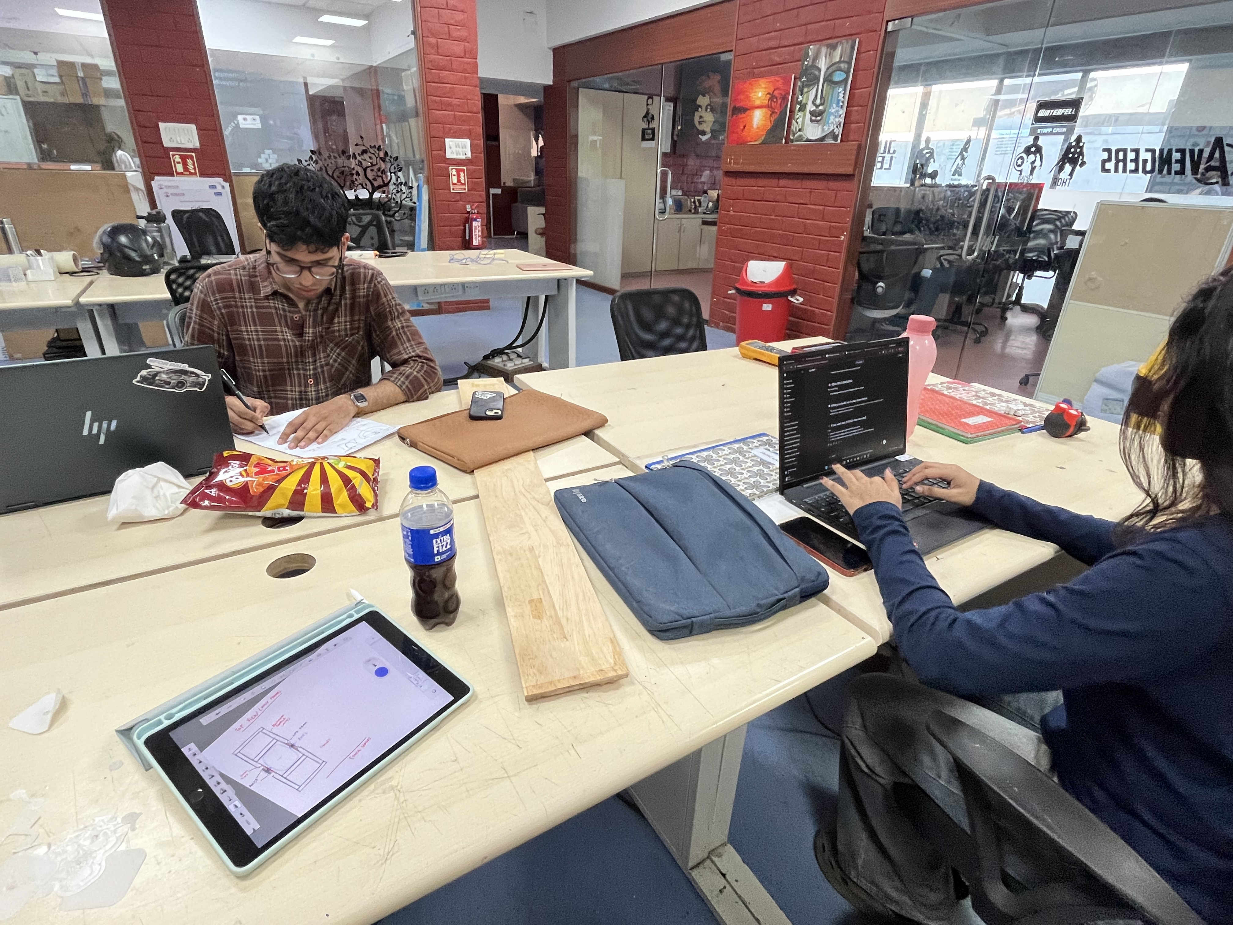
We started by jotting down potential ideas that we could complete in the time span
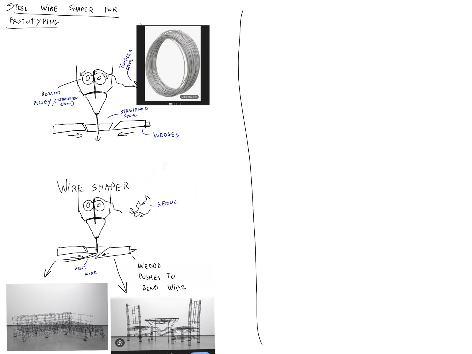
This was one of the ideas,
A steel wire bender that can be used for Wireframe prototyping
We bounced around a few more ideas such as:
We finally decided to make a onewheel
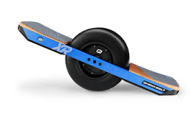
Something like this.
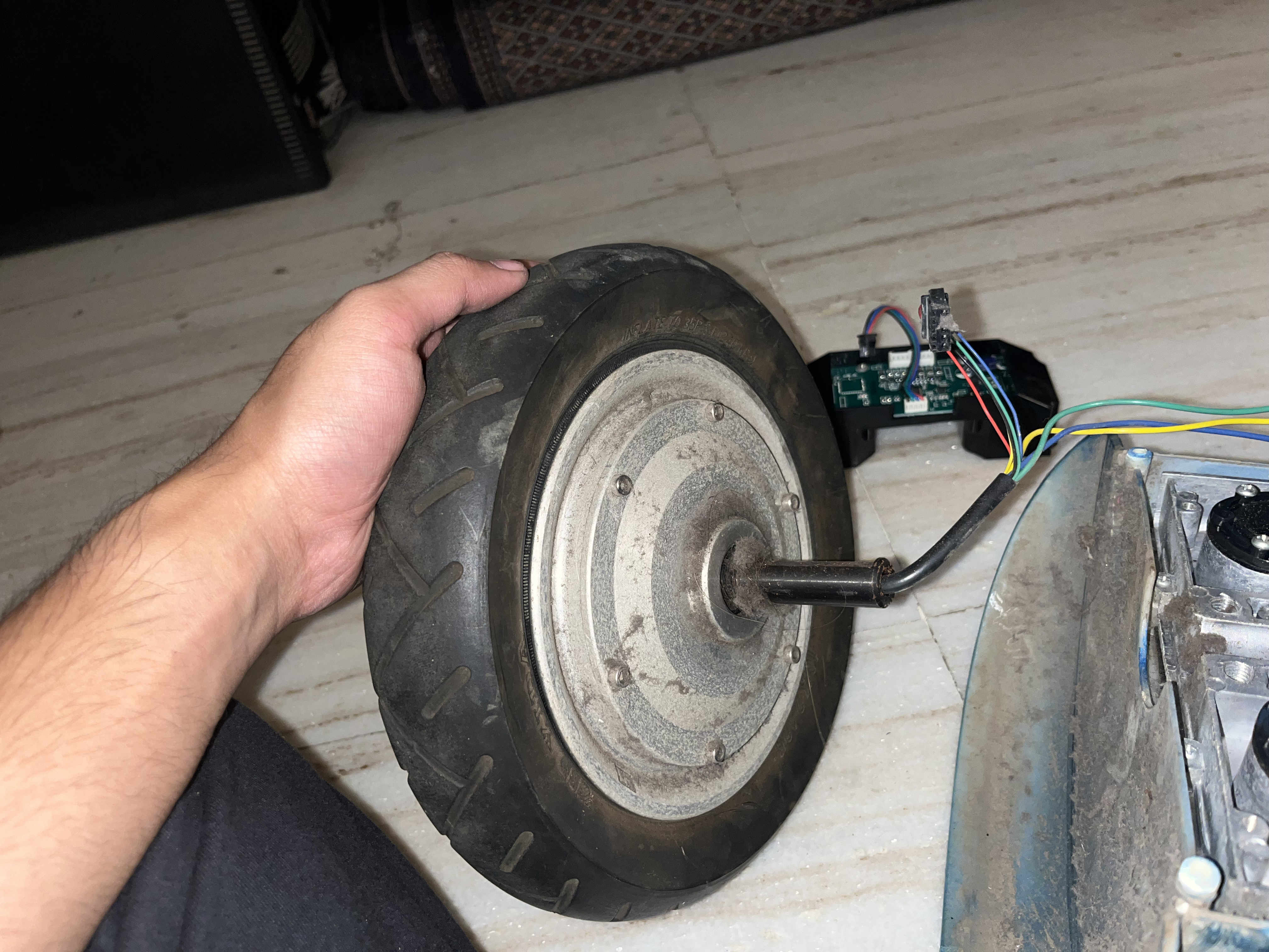
Here is a jub motor
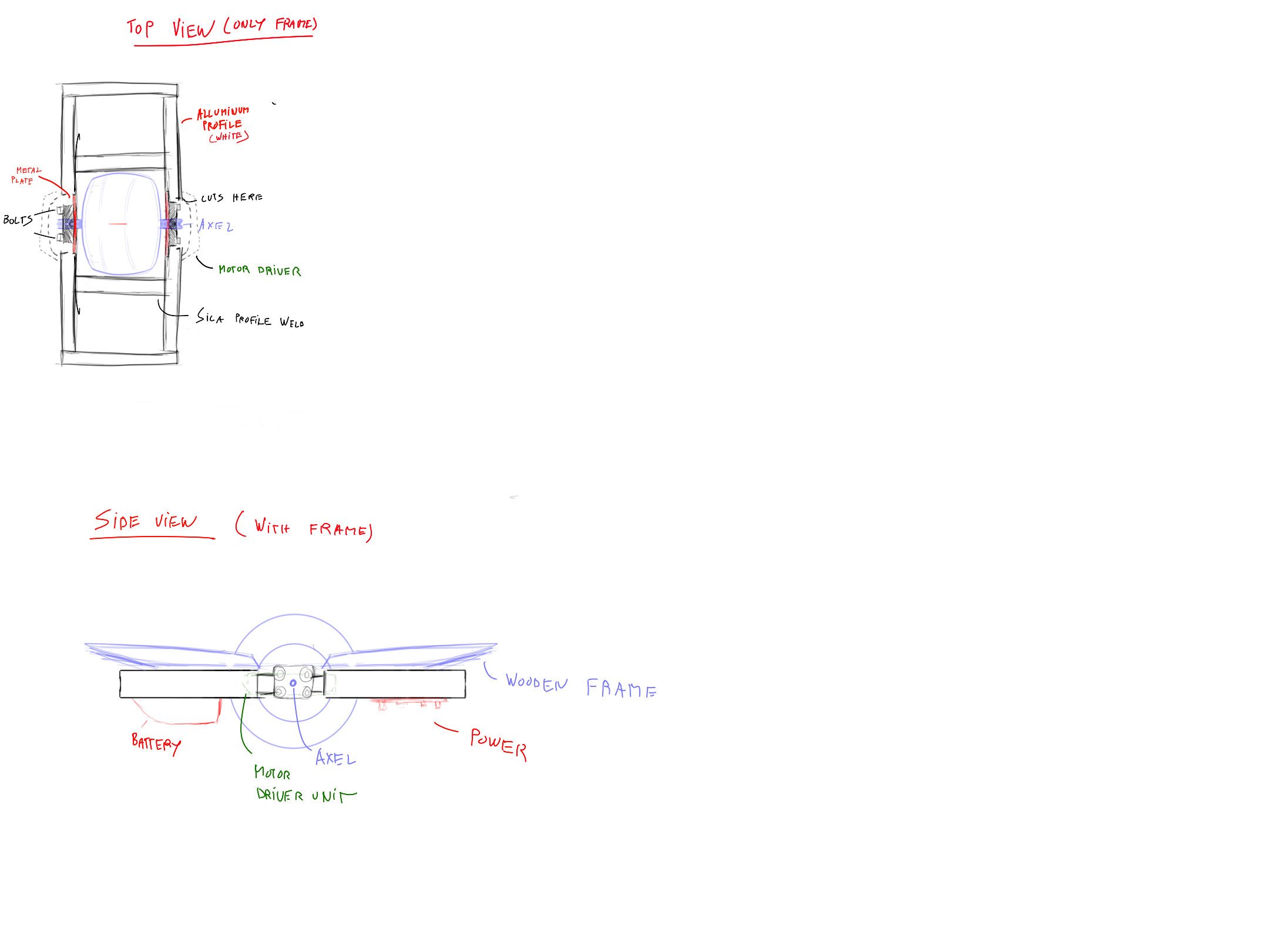
this was the plan fo the project.

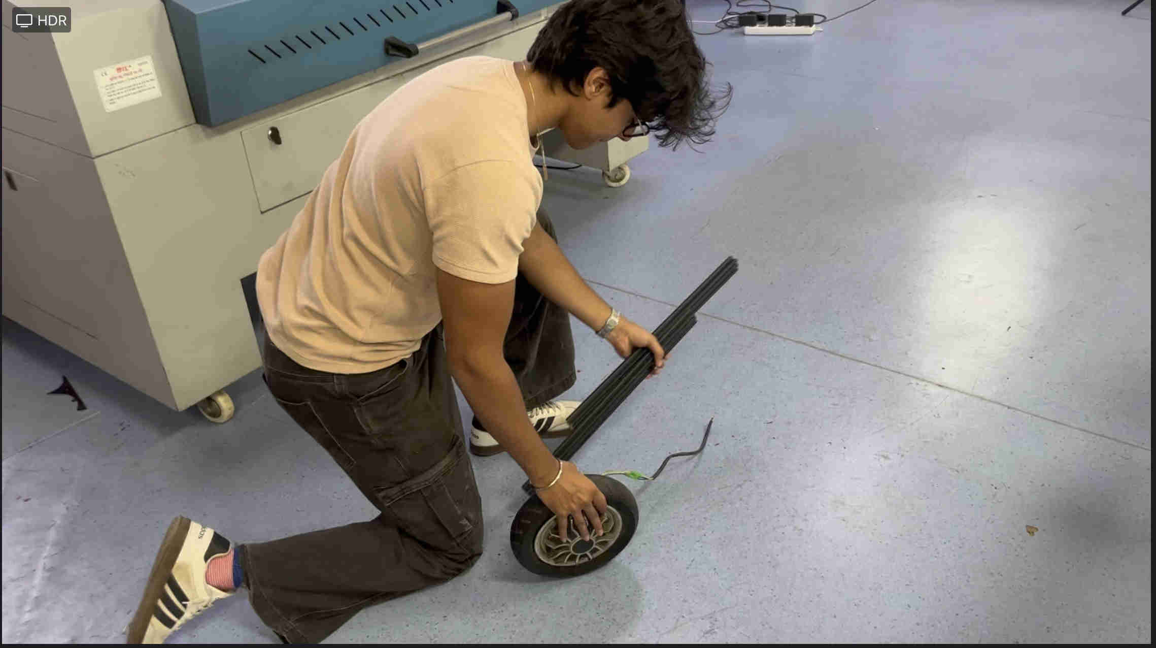
Some working shots.
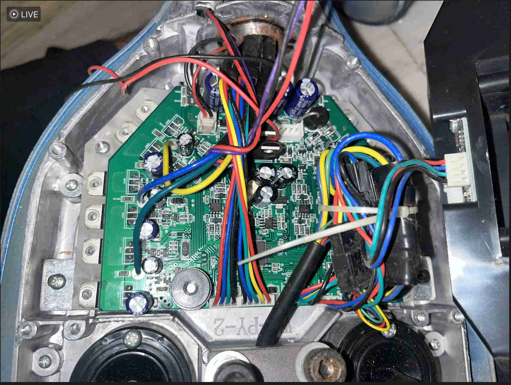
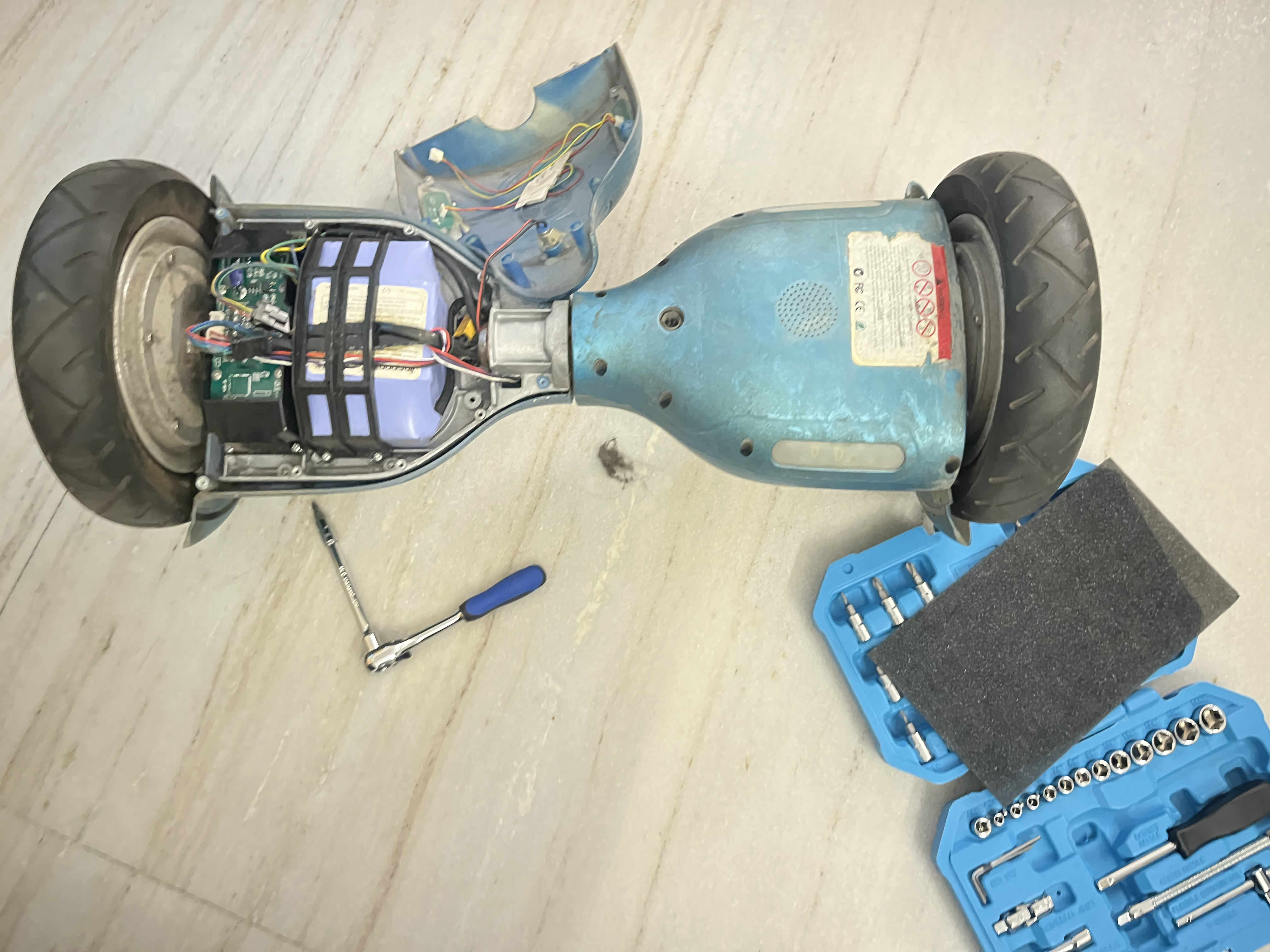
these were parts insid ethe hoverboard EXTREMELY PROPRIETERY.
Automatic intra office deleivery robot/ drawing enthusiast.
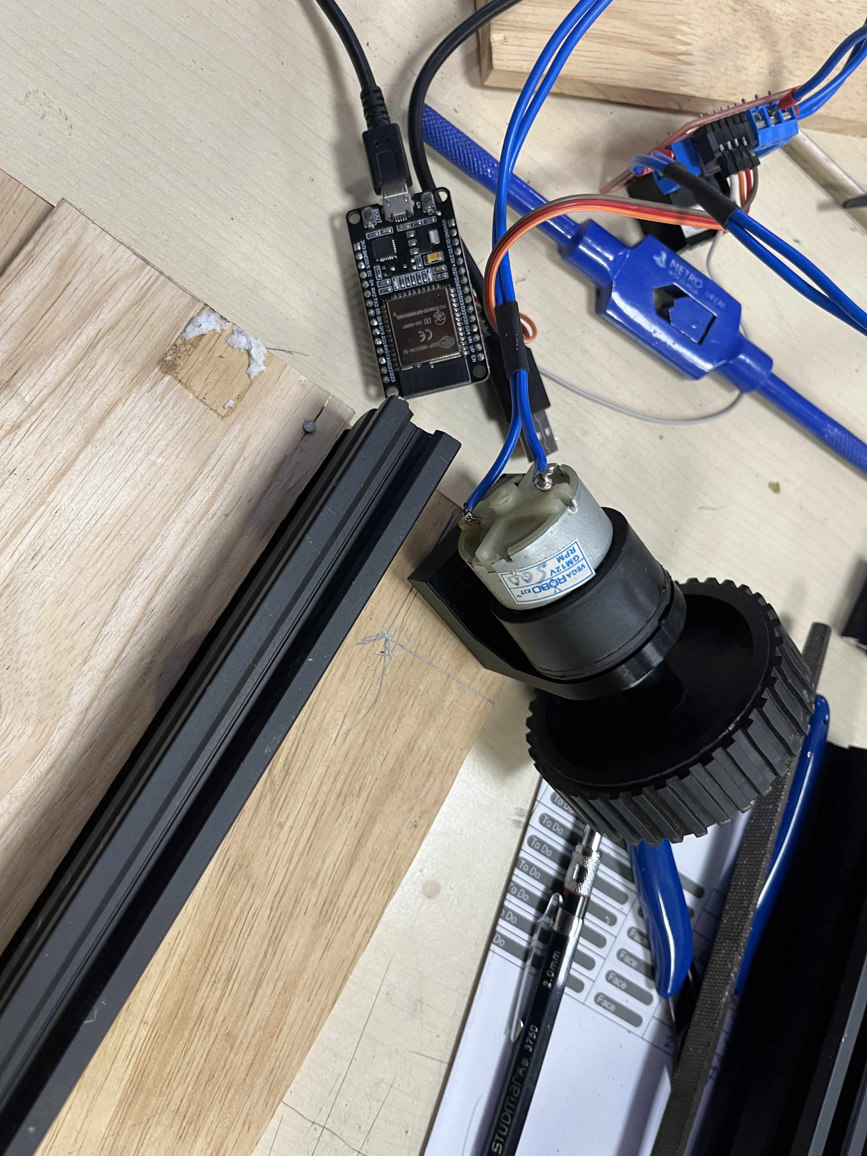
Designed a custom mount for the motor and wires.
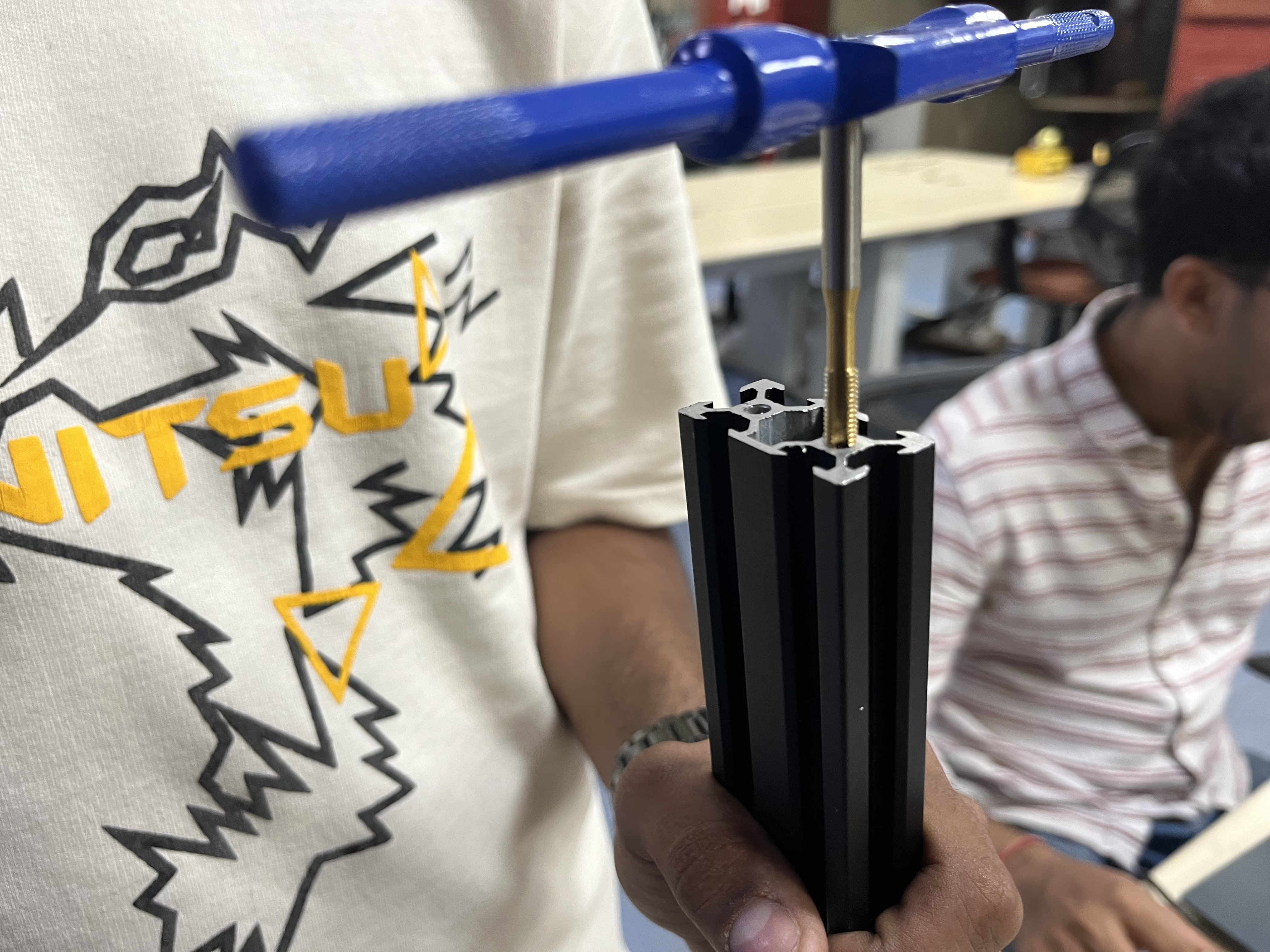
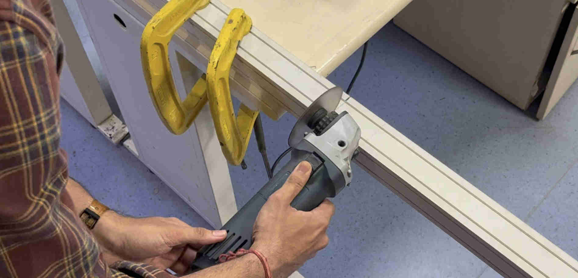
Tapping sica profiles, for screwing 3d printed mounts.
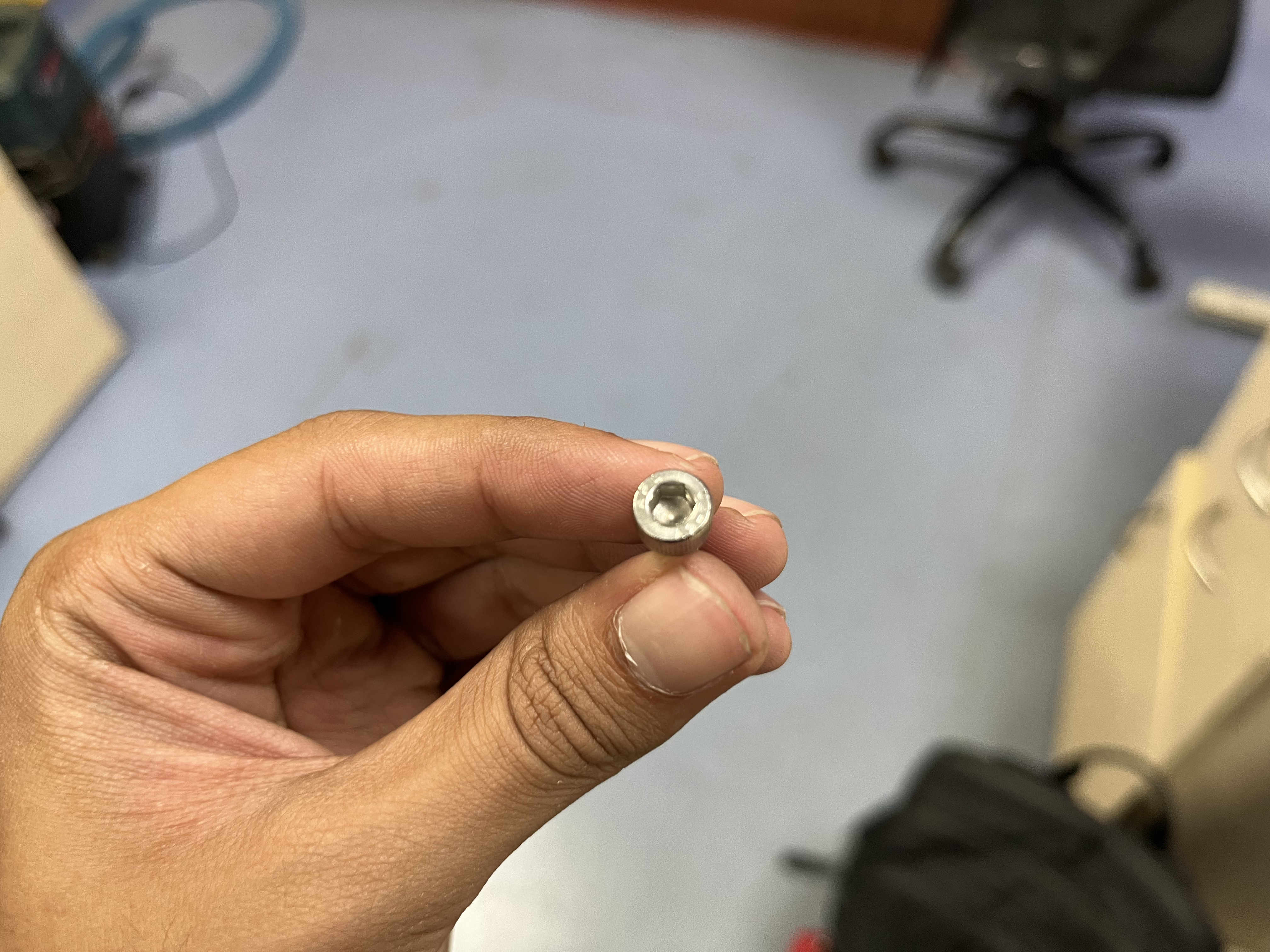
Using M3 bolts for the entire design
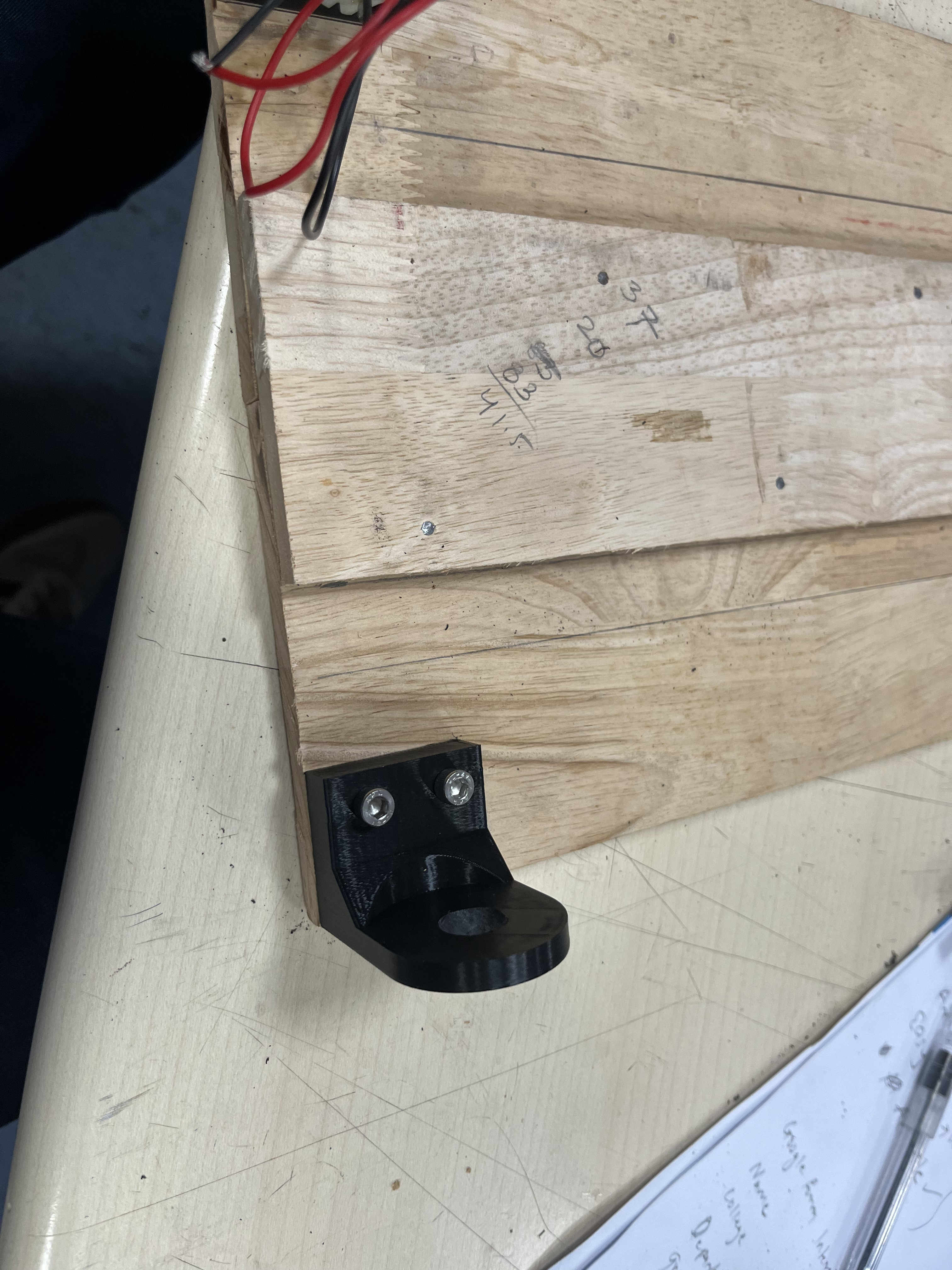
Mounted.
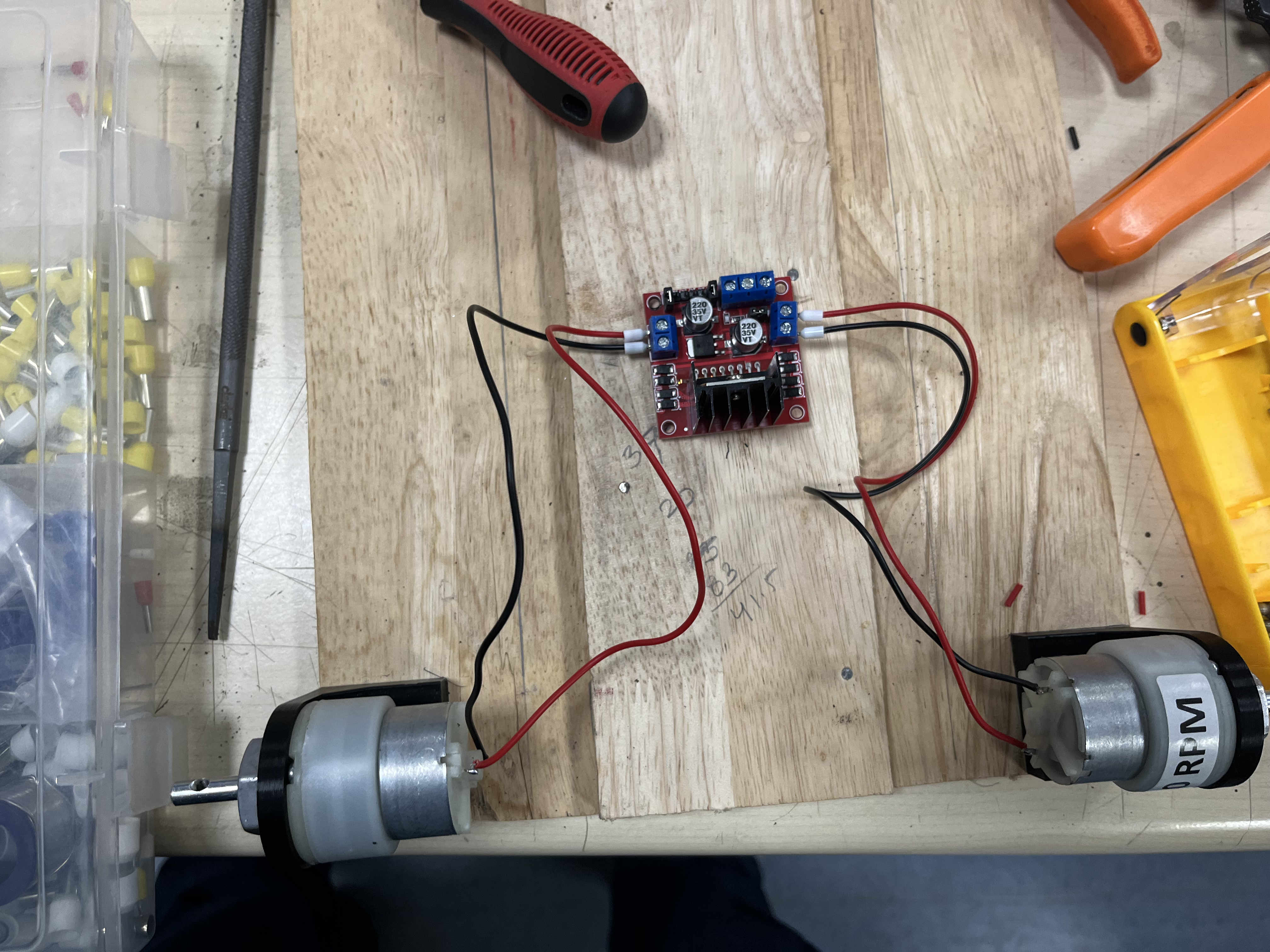
Crimped wires and properly mounted.
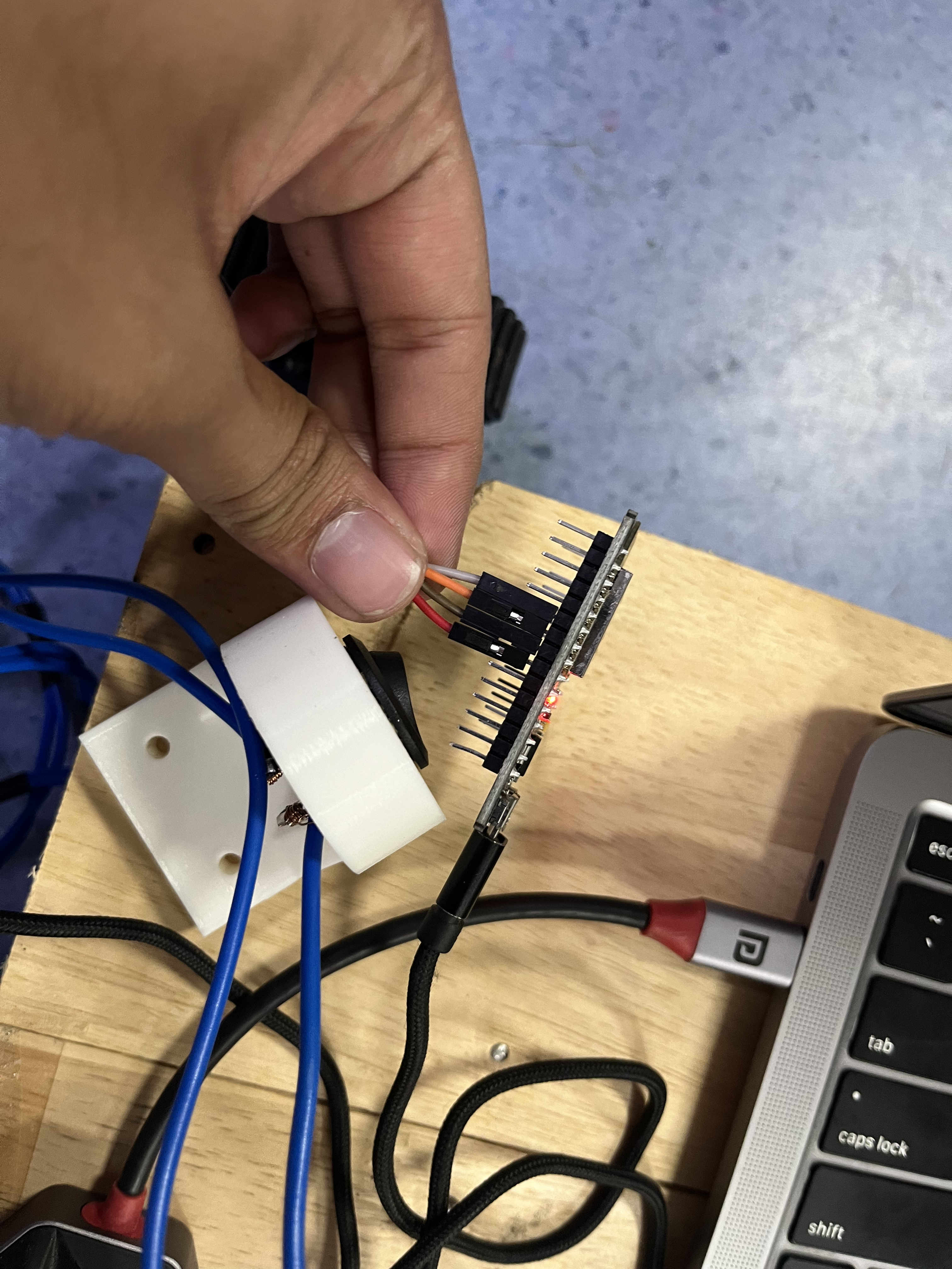
as u see the corner two have to be jumped.
This was the first test with everything working and esp powered by laptop.
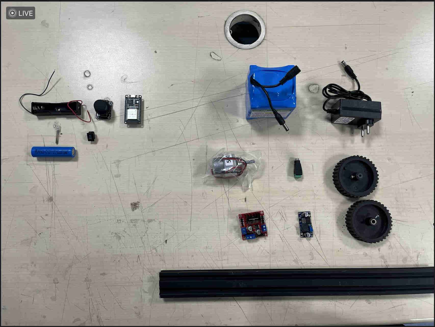
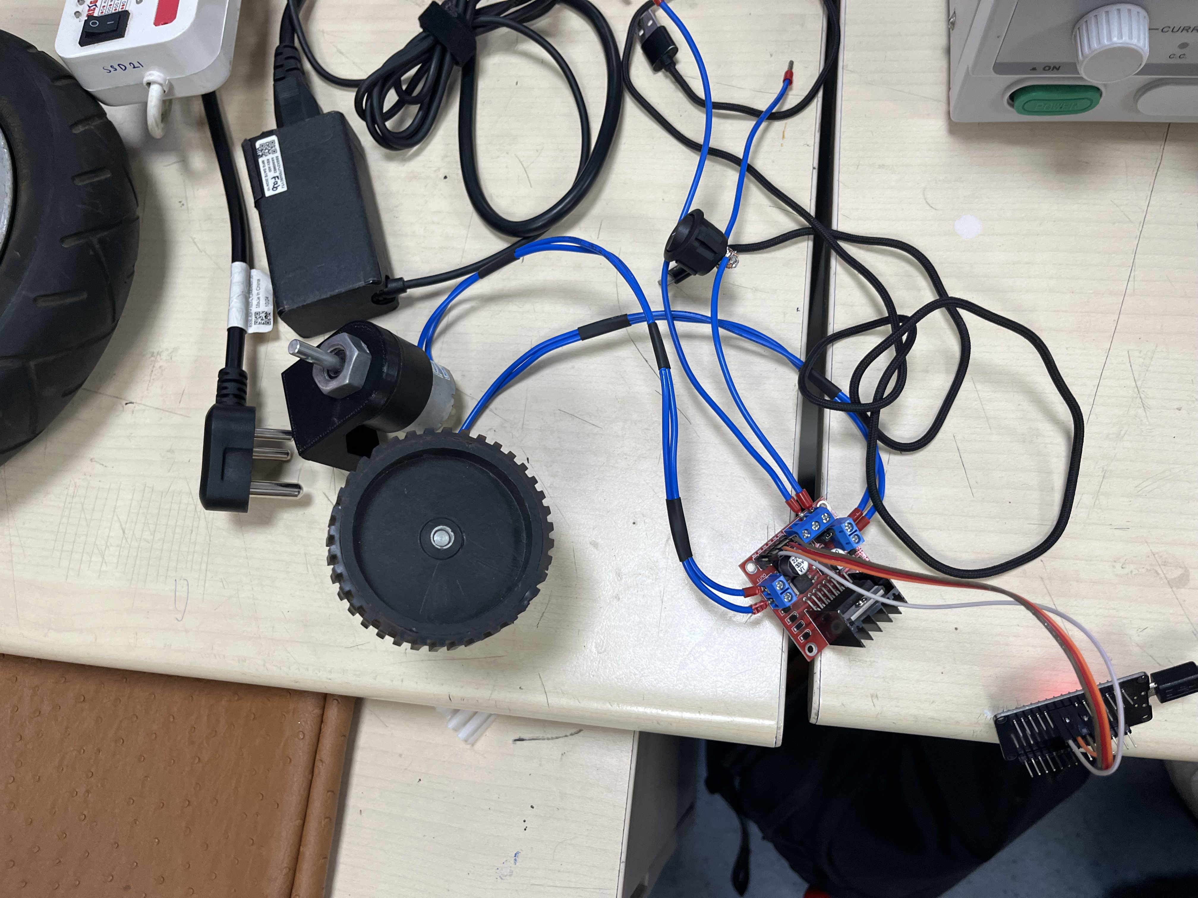
These were all the components required.
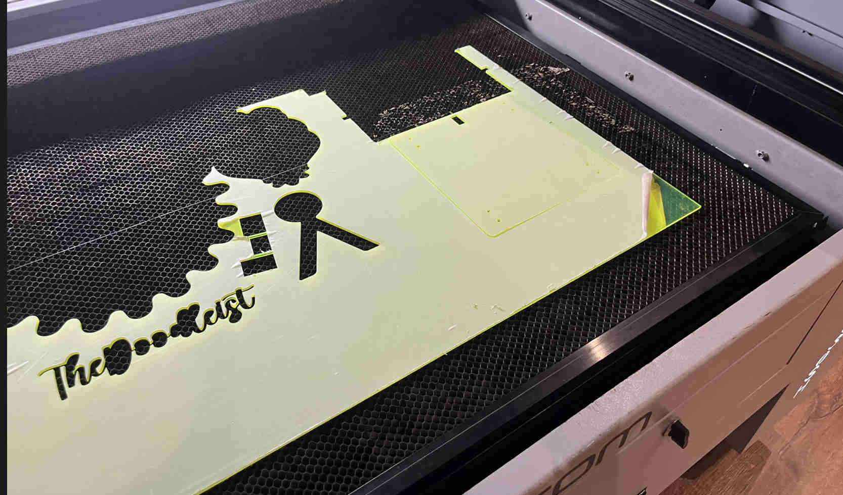
Decided to switch to acryllic, for a lighter cooler final thing.
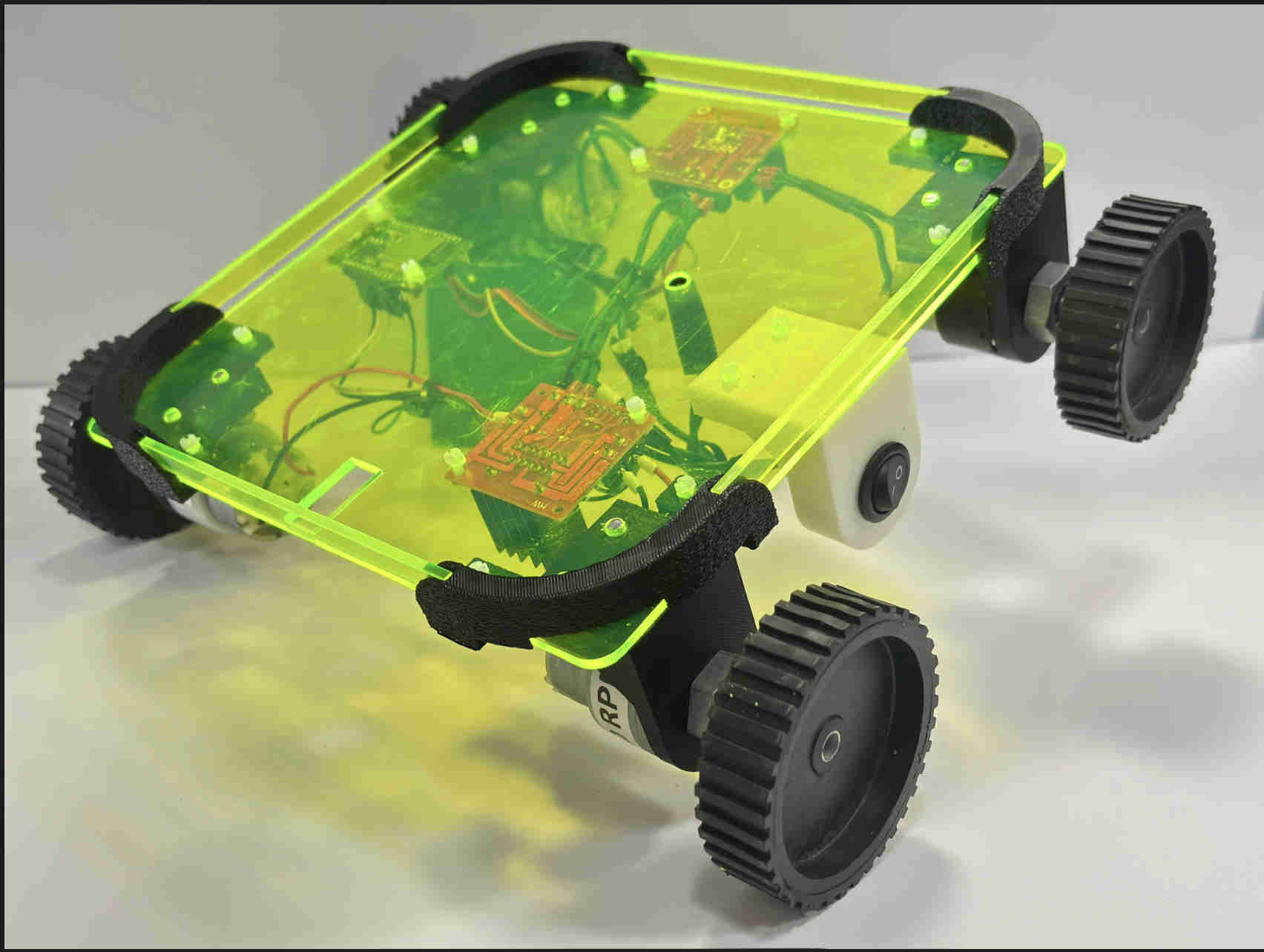
Assembling all components.
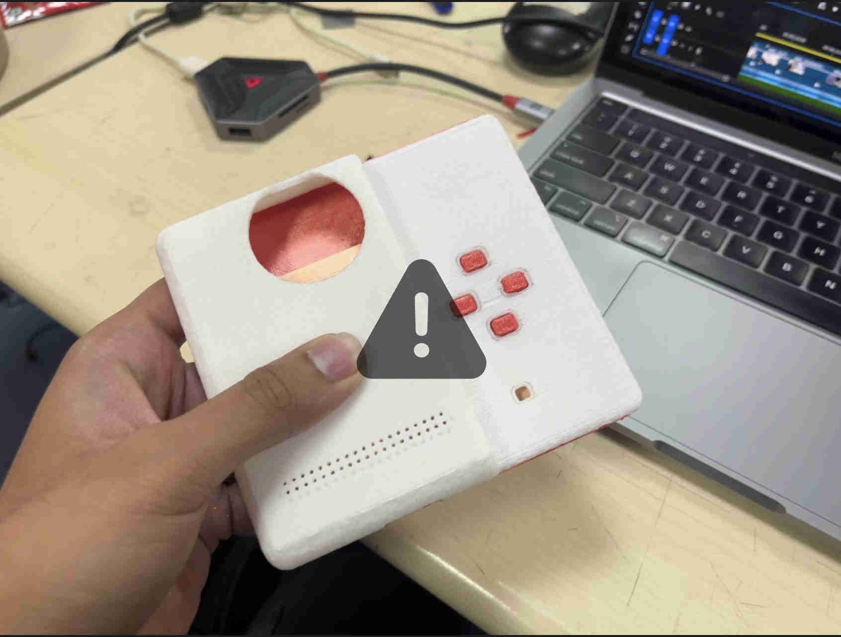
Designed a custom controller for the model, with joystick and buttons