Interface design
For this week i design my interface that i will use for my final project.
The basic funtion of the interface, is to take camera data at whatever resolution, and convert it to a 36 by 42 led matrix that has to be shot ourt every 10 degrees of rotation of the neopixels.
LOGIC
how this code works is very straight forward,
In its essence every image is divided into a series of RGB colour values, depending on how dense the pixels are, the values sent increase and an areas colour can be manipulated by carefully selecting which pixel glows at what value.
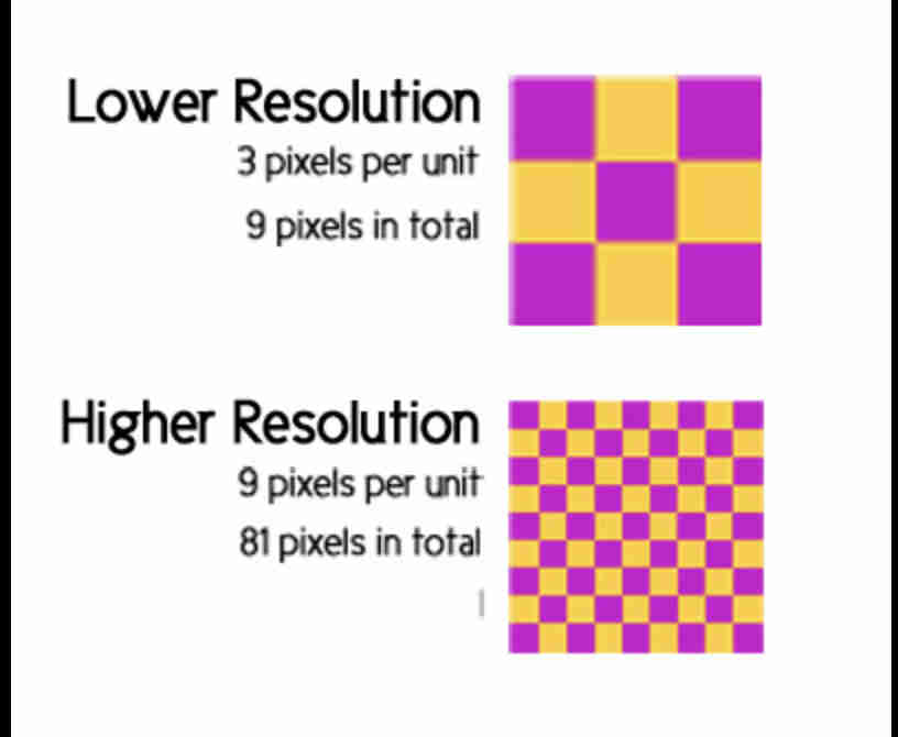
why this matters is that-
THUS
We have to consder the size and spacing of each neopixel, use that as a reference on our camera feed,
meaning-
Step 1
I started by creating a basic html file that has all the options that i need,
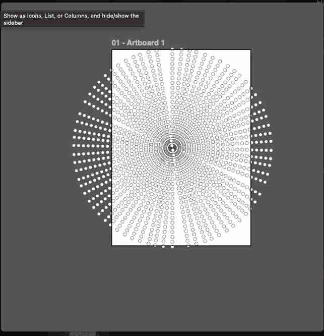
Next I calculated my neopixel size, and recreated the exact effect and potential display at 1200 rpms, on illustrator.
This was important to carefully design the interface such that-

These arent working buttons, these are just place holders, and a basic html INTERFACE
Next i took the help of claude to build a working interface
  # Claude 4 Prompt — Create a Single HTML Web App for an ESP32 POV NeoPixel Display

You are an expert JavaScript, HTML5 Canvas, WebRTC, WebSocket, image-processing, and embedded systems developer.

Create a **single self-contained HTML file** (HTML + CSS + JavaScript only, no frameworks, no React, no external libraries) that functions as a polished desktop web application for controlling an ESP32-powered Persistence of Vision (POV) display.

The code should be clean, modular, heavily commented, and production-quality.

---

# Project Overview

The webpage should:

1. Connect to an ESP32 over Wi-Fi using WebSockets.
2. Enable the laptop webcam.
3. Capture the live camera feed.
4. Process every frame in real time.
5. Convert the processed image into data suitable for a spinning NeoPixel POV display.
6. Continuously transmit that processed LED data to the ESP32.
7. Display live previews and system status.

The HTML should feel like a professional control dashboard rather than a simple demo.

---

# Display Specifications

The physical display consists of:

* 42 NeoPixel LEDs
* Arranged in a single straight line
* Rotating at high speed
* Creating a full circular image using Persistence of Vision

The webpage should internally treat the image as:

* 360 angular slices
* Each slice containing 42 RGB pixels

The processed image should therefore be converted into polar coordinates before transmission.

---

# User Interface

Design a clean, modern dark interface using glassmorphism styling.

The layout should contain separate cards for:

### ESP32 Connection

Include:

* ESP32 IP Address input
* Connect button
* Disconnect button
* Connection status indicator
* Ping / Latency display

---

### Camera

Include:

* Enable Camera
* Disable Camera
* Camera selector
* Resolution selector
* Live webcam preview

---

### Processing Mode

Keep the interface simple.

Only include these processing modes:

* Normal
* Black & White
* Thermal
* Inverse
* High Contrast

Use a dropdown selector.

---

### Image Adjustments

Provide real-time sliders for:

* Brightness
* Contrast
* Blacks
* Whites
* Exposure
* Saturation
* Hue
* Gamma
* Sharpness

Also include individual color adjustments:

* Cyan
* Magenta
* Yellow
* Black (CMYK-style adjustment)

Each slider should update the preview instantly without restarting the camera.

---

### POV Display Settings

Include only the essentials:

* LED Count (default 42)
* Angular Resolution (default 360)
* Rotation Offset
* LED Brightness

---

### Live Preview Area

Display three previews side-by-side:

1. Original Camera Feed
2. Processed Image
3. Simulated Circular POV Display

The circular preview should accurately simulate what the spinning LED strip will display after the polar conversion.

---

# Image Processing Pipeline

Every frame should follow this workflow:

Camera

↓

Canvas

↓

Selected Processing Mode

↓

Brightness / Contrast / Color Adjustments

↓

Resize

↓

Polar Coordinate Conversion

↓

Generate 42 LED radial samples

↓

Transmit to ESP32

---

# Polar Conversion

Implement a proper rectangular-to-polar mapping.

For every angular slice:

* Sample the processed image
* Generate exactly 42 radial samples
* Convert each sample into RGB values
* Store them in transmission order

Use smooth interpolation to avoid jagged artifacts.

---

# ESP32 Communication

Use WebSockets.

Features should include:

* Connect
* Disconnect
* Automatic reconnect
* Binary frame transmission
* Connection status
* Error handling

Display:

* Connected
* Connecting
* Disconnected

using colored status indicators.

---

# Performance

The application should aim for smooth real-time performance.

Use:

* requestAnimationFrame()
* OffscreenCanvas where supported
* Typed Arrays
* Efficient memory management

Avoid unnecessary allocations every frame.

---

# Debug Panel

Display:

* Camera FPS
* Processing FPS
* Transmission FPS
* Current Processing Mode
* Current Resolution
* LED Count
* Angular Resolution
* Packet Size
* Connection Latency

---

# Code Structure

Organize the JavaScript into clear functions such as:

* connectESP32()
* disconnectESP32()
* startCamera()
* stopCamera()
* captureFrame()
* processFrame()
* applyFilters()
* polarTransform()
* drawPOVPreview()
* encodeFrame()
* sendFrame()
* updateUI()

Avoid placing all logic inside one large function.

---

# Styling

The UI should resemble a professional hardware control application.

Requirements:

* Dark theme
* Glassmorphism cards
* Rounded corners
* Soft shadows
* Blue accent colors
* Smooth hover animations
* Responsive layout
* Clean typography
* Minimal but premium appearance

---

# Error Handling

Gracefully handle:

* Camera permission denied
* Camera unavailable
* ESP32 offline
* WebSocket disconnect
* Invalid IP address
* Processing failures

Display clear, user-friendly messages instead of console-only errors.

---

# Output Requirement

Return **one complete HTML file** containing:

* HTML
* CSS
* JavaScript

Everything should be embedded in the single file.

Do **not** use external libraries, frameworks, placeholders, or pseudo-code.

The result should feel like a polished, professional application that is immediately usable as the control interface for a real-time ESP32-powered 42-LED Persistence of Vision display.
This is the prompt I gave claude for the begining of the project and then moved on to making edits as and when needed
Steps to use the interface
Upload this code to your esp32 xiao.
#include
#include
#include

const char* ap_ssid = "HoloFan";
const char* ap_password = "holofan123";

#define LED_PIN D0
#define NUM_LEDS 42
#define NUM_COLS 36
#define CENTER_LED 21

Adafruit_NeoPixel strip(NUM_LEDS, LED_PIN, NEO_GRB + NEO_KHZ800);
WebSocketsServer webSocket(81);

uint8_t imageData[NUM_COLS][NUM_LEDS][3];
bool hasImage = false;
bool clientConnected = false;
uint32_t colDelay = 2222;

// ─── STARTUP ANIMATION ───────────────────────────────────
void startupAnimation() {
  // Center outward pulse — 3 times
  for(int repeat = 0; repeat < 3; repeat++) {
    // Expand from center outward
    for(int radius = 0; radius <= CENTER_LED; radius++) {
      strip.clear();
      for(int r = 0; r <= radius; r++) {
        float brightness = 1.0 - (float)(radius - r) / 6.0;
        if(brightness < 0) brightness = 0;
        uint8_t b = (uint8_t)(brightness * 255);
        int ledA = CENTER_LED + r;
        int ledB = CENTER_LED - r;
        if(ledA < NUM_LEDS) strip.setPixelColor(ledA, strip.Color(b, b, b));
        if(ledB >= 0)        strip.setPixelColor(ledB, strip.Color(b, b, b));
      }
      strip.show();
      delay(18);
    }
    // Collapse back
    for(int radius = CENTER_LED; radius >= 0; radius--) {
      strip.clear();
      for(int r = 0; r <= radius; r++) {
        float brightness = 1.0 - (float)(radius - r) / 6.0;
        if(brightness < 0) brightness = 0;
        uint8_t b = (uint8_t)(brightness * 255);
        int ledA = CENTER_LED + r;
        int ledB = CENTER_LED - r;
        if(ledA < NUM_LEDS) strip.setPixelColor(ledA, strip.Color(b, b, b));
        if(ledB >= 0)        strip.setPixelColor(ledB, strip.Color(b, b, b));
      }
      strip.show();
      delay(18);
    }
    delay(100);
  }

  // Color sweep — white to cyan to blue
  for(int i = 0; i < NUM_LEDS; i++) {
    strip.clear();
    for(int j = 0; j <= i; j++) {
      float t = (float)j / NUM_LEDS;
      uint8_t r = (uint8_t)(255 * (1.0 - t));
      uint8_t g = (uint8_t)(200 * t);
      uint8_t b = 255;
      strip.setPixelColor(j, strip.Color(r, g, b));
    }
    strip.show();
    delay(12);
  }
  delay(200);
  strip.clear();
  strip.show();
}

// ─── RED BREATHING (waiting for connection) ──────────────
void breatheRed() {
  // One full breath cycle
  // Fade in
  for(int b = 0; b <= 80; b += 3) {
    for(int i = 0; i < NUM_LEDS; i++) {
      strip.setPixelColor(i, strip.Color(b, 0, 0));
    }
    strip.show();
    delay(15);
  }
  // Fade out
  for(int b = 80; b >= 0; b -= 3) {
    for(int i = 0; i < NUM_LEDS; i++) {
      strip.setPixelColor(i, strip.Color(b, 0, 0));
    }
    strip.show();
    delay(15);
  }
  delay(300);
}

// ─── CONNECTED FLASH ─────────────────────────────────────
void connectedFlash() {
  // Green flash 3 times
  for(int rep = 0; rep < 3; rep++) {
    for(int i = 0; i < NUM_LEDS; i++)
      strip.setPixelColor(i, strip.Color(0, 255, 0));
    strip.show();
    delay(120);
    strip.clear();
    strip.show();
    delay(120);
  }
  strip.clear();
  strip.show();
}

// ─── WEBSOCKET ────────────────────────────────────────────
void webSocketEvent(uint8_t num, WStype_t type, uint8_t* payload, size_t length) {
  switch(type) {
    case WStype_CONNECTED:
      Serial.printf("[%u] Browser connected!\n", num);
      clientConnected = true;
      connectedFlash();
      break;

    case WStype_DISCONNECTED:
      Serial.printf("[%u] Disconnected!\n", num);
      clientConnected = false;
      hasImage = false;
      break;

    case WStype_BIN:
      // Full image — 36 cols × 42 LEDs × 3 bytes
      if(length == NUM_COLS * NUM_LEDS * 3) {
        for(int col = 0; col < NUM_COLS; col++)
          for(int led = 0; led < NUM_LEDS; led++) {
            int idx = (col * NUM_LEDS + led) * 3;
            imageData[col][led][0] = payload[idx];
            imageData[col][led][1] = payload[idx+1];
            imageData[col][led][2] = payload[idx+2];
          }
        hasImage = true;
      }
      // Timing update — 2 bytes
      if(length == 2) {
        colDelay = (payload[0] << 8) | payload[1];
        Serial.printf("Timing: %d us/col\n", colDelay);
      }
      break;
  }
}

// ─── SETUP ───────────────────────────────────────────────
void setup() {
  Serial.begin(115200);
  strip.begin();
  strip.setBrightness(30);
  strip.show();

  // Run startup animation
  startupAnimation();

  // Start WiFi AP
  WiFi.mode(WIFI_AP);
  WiFi.softAP(ap_ssid, ap_password);
  Serial.print("HoloFan IP: ");
  Serial.println(WiFi.softAPIP());

  webSocket.begin();
  webSocket.onEvent(webSocketEvent);
  Serial.println("Waiting for browser connection...");
}

// ─── LOOP ────────────────────────────────────────────────
void loop() {
  webSocket.loop();

  if(clientConnected && hasImage) {
    // Stream POV image
    uint32_t rotStart = micros();
    for(int col = 0; col < NUM_COLS; col++) {
      webSocket.loop();
      for(int led = 0; led < NUM_LEDS; led++) {
        strip.setPixelColor(led, strip.Color(
          imageData[col][led][0],
          imageData[col][led][1],
          imageData[col][led][2]
        ));
      }
      strip.show();
      uint32_t target = rotStart + (uint32_t)(col + 1) * colDelay;
      int32_t wait = (int32_t)(target - micros());
      if(wait > 0) delayMicroseconds(wait);
    }
  } else if(!clientConnected) {
    // Red breathing while waiting for connection
    breatheRed();
    webSocket.loop();
  }
}
Once uploaded power the board
We are usoing the websocket method which has a lower latency than using ESPNOW with an external router
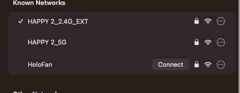
Go to available networks on your device ayour custom SSID name should appear,
Enter the password that you have set
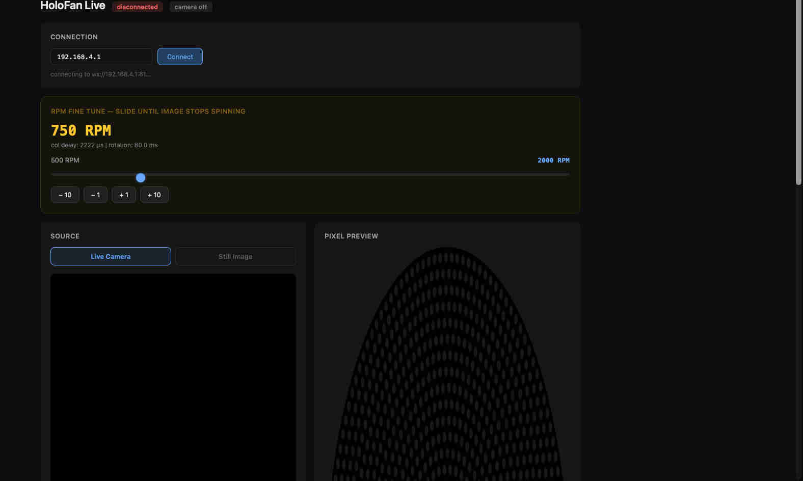
Open the html file and click on connect
This is the landing page
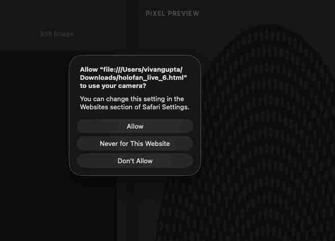
Once you click enable camera this should pop up

The greenbar indiciates that its connected.
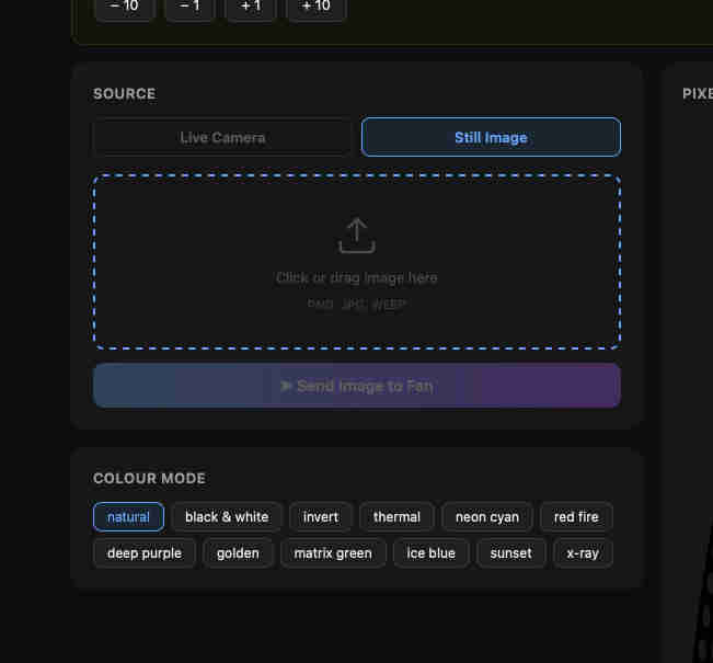
This is the section where you can upload files.
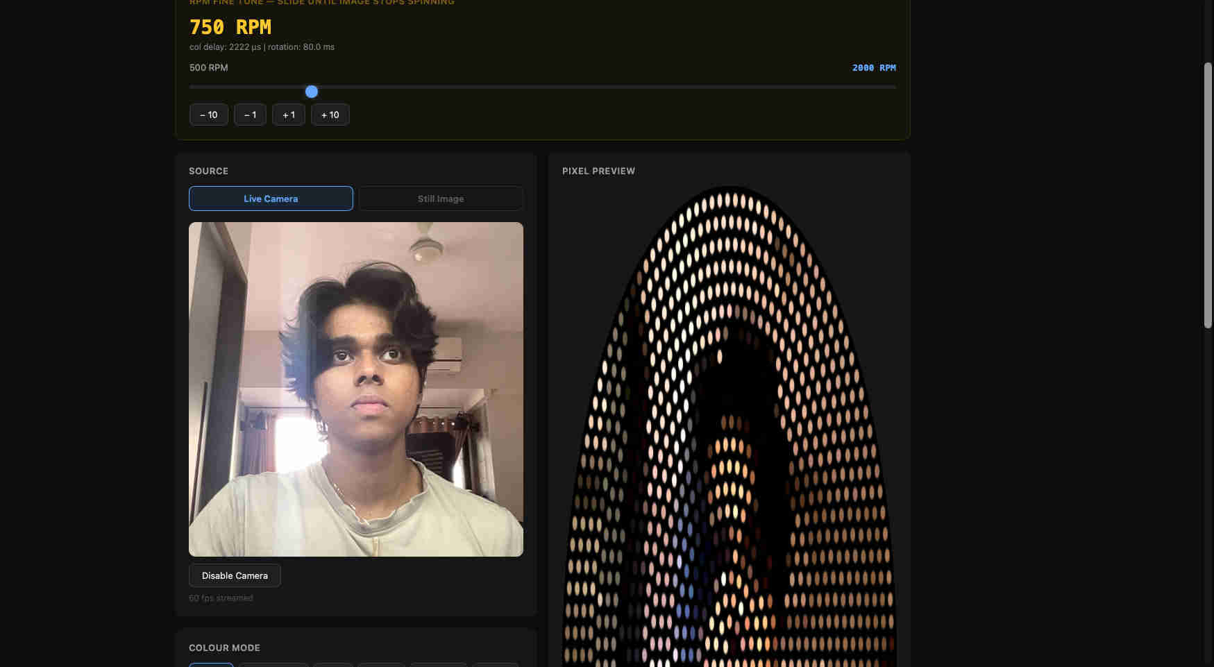
or live interface with live feed for camera
The interface is designed specifically for this application thus it has many settings catered just for this project.
Brightness contrast zoom and more.

various colour modes for crazyyyyyy effects.
Final interface videos
here is the final interface in use by one of mt friends
And here it is in full effect.