.OUTPUT devices.
This week we explore output devices
For my final project involving a holograpghic fan, I thought its ideal to explore neopixels and bldc motors for this week
First step was understanding a bldc motor and neopixel
⚡ What is a BLDC Motor?
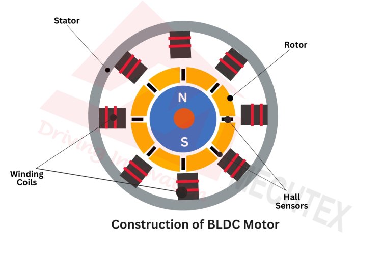
A Brushless DC (BLDC) motor is a motor that spins without using brushes. Instead, it uses magnets and electronic control to create motion.
🧲 How Does It Work?
Inside the motor, there are coils (electromagnets) and a rotating part with permanent magnets. The controller turns the coils on and off in a sequence, creating a moving magnetic field.
This makes the rotor “chase” the magnetic field — causing it to spin continuously 🔄
🎯 Why is it Cool?
No brushes means:
- Less friction ⚙️
- Less noise 🔇
- Higher efficiency 🚀
- Longer life ⏳
⚡ Where Do You See It?
BLDC motors are used in:
- Fans
- Drones
- Electric vehicles
- Computer cooling systems
🧠 Simple Way to Imagine
Imagine turning on magnets one after another in a circle — the rotor keeps following them like a game of “follow the leader” 🎯
🌈 What is a NeoPixel?
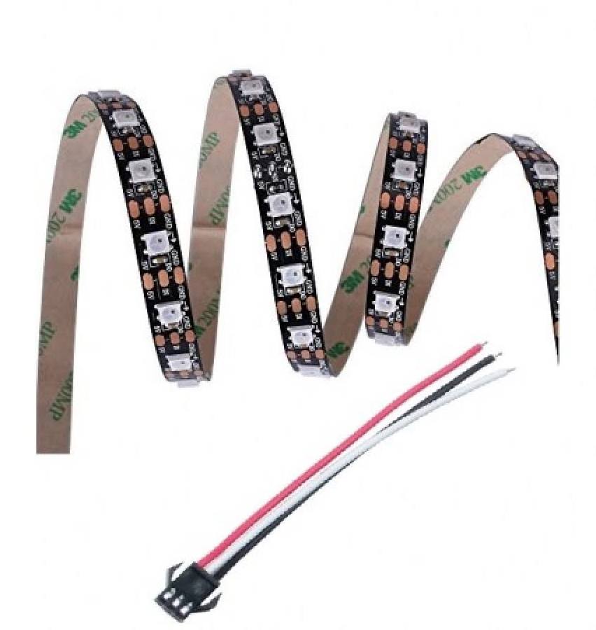
A NeoPixel is a smart LED that you can control individually using code. Each tiny light can show its own color and brightness.
🎛️ How Does It Work?
NeoPixels have a tiny chip inside them. You send data through one wire, and each LED understands what color it should display.
The signal passes from one LED to the next — like a chain of instructions 🔗
🎨 Why is it Cool?
- Each LED is individually controllable 🎯
- Millions of colors possible 🌈
- Only one data wire needed 🔌
- Can create animations and effects ✨
⚡ Where Do You See It?
- LED strips and panels
- Wearable tech
- Gaming setups
- Art installations
🧠 Simple Way to Imagine
Imagine a line of tiny light bulbs passing messages to each other — each one lights up in its own color when it gets its instruction 📩
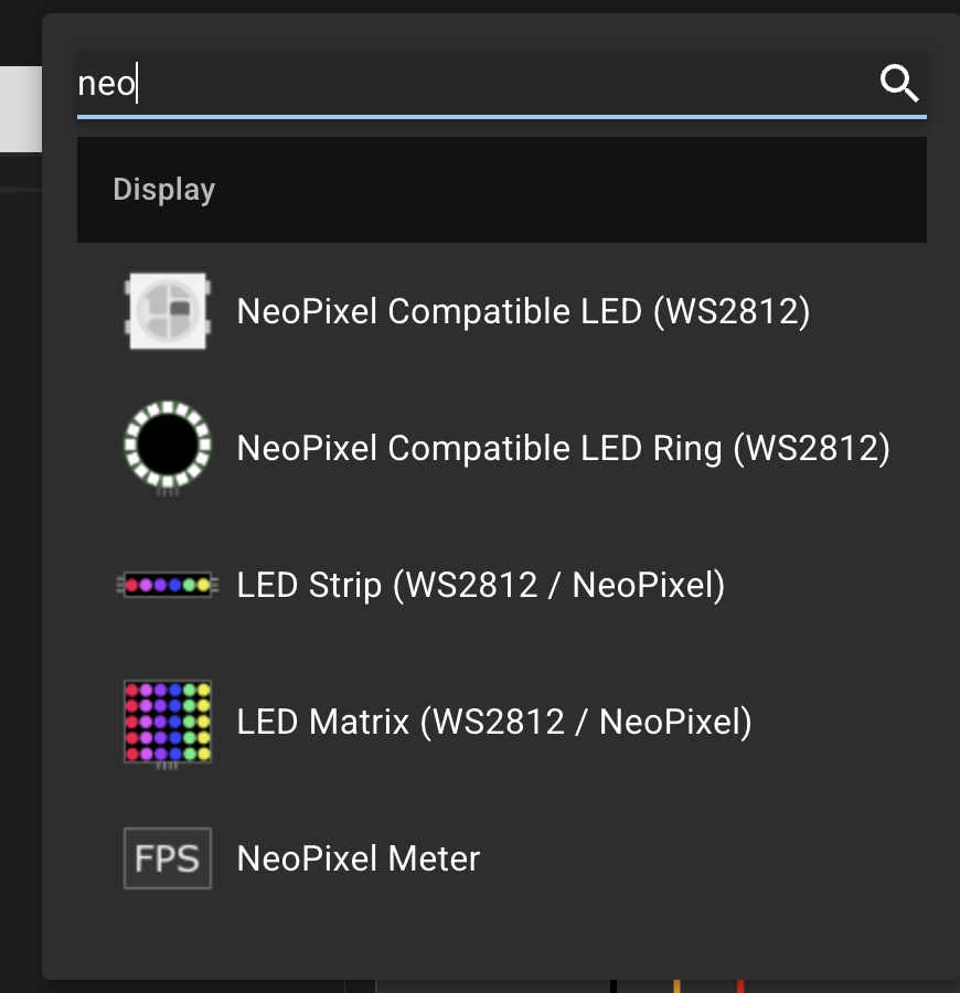
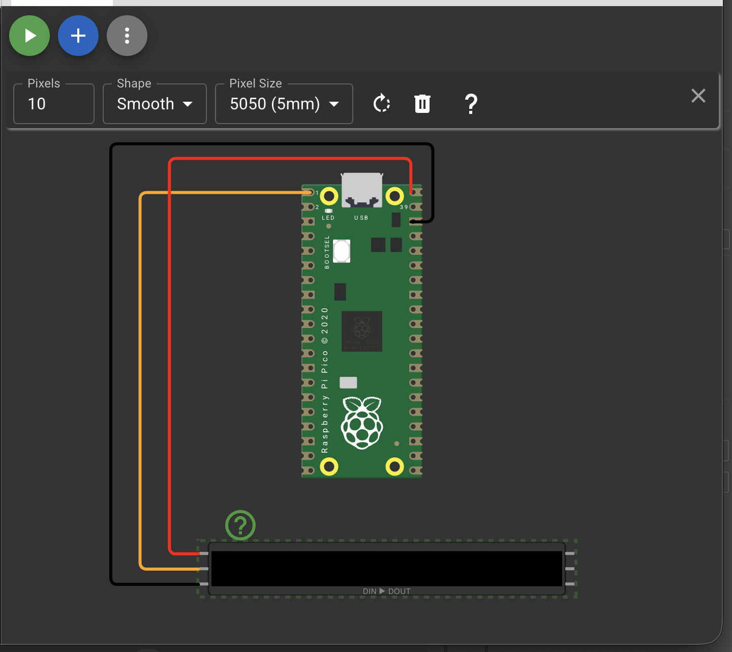
After this I started simulations on wokwi
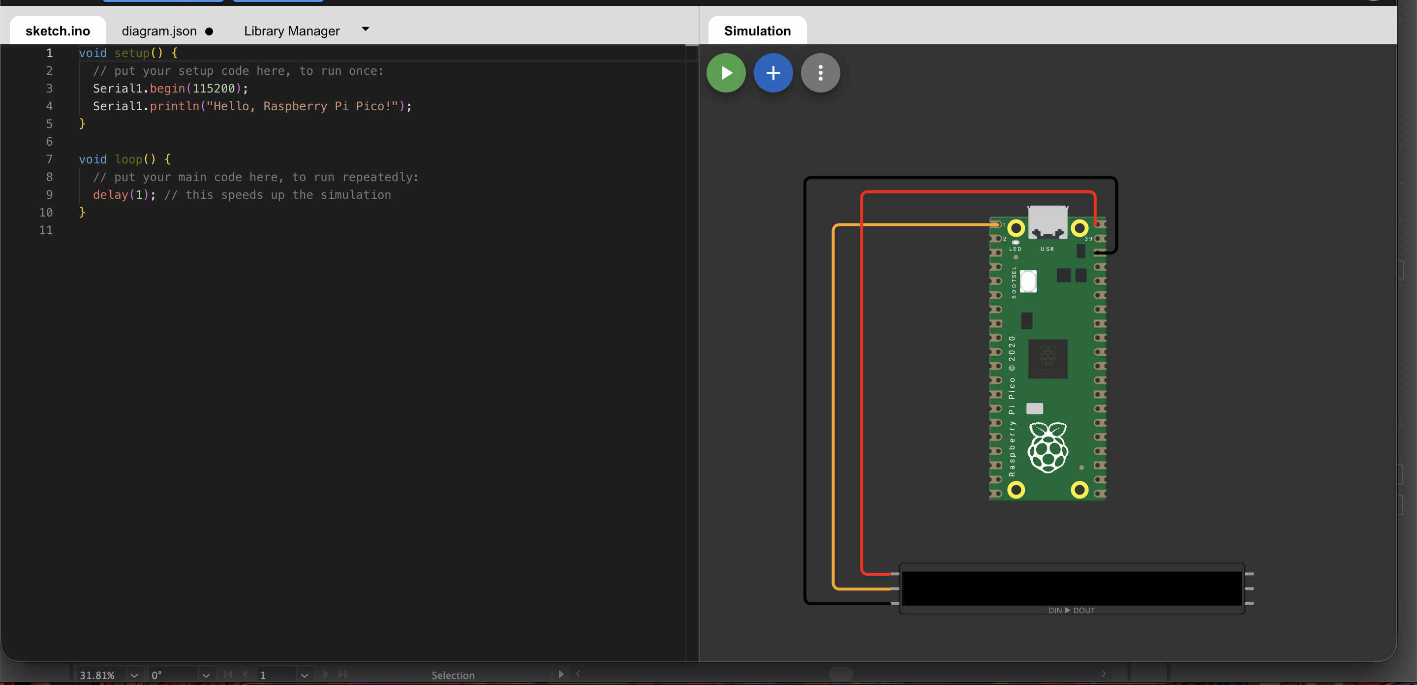
#include

#define PIN 0          // GP0 on Pico
#define NUMPIXELS 1    // Number of NeoPixels

Adafruit_NeoPixel pixel(NUMPIXELS, PIN, NEO_GRB + NEO_KHZ800);

void setup() {
  pixel.begin();
}

void loop() {
  // RED
  pixel.setPixelColor(0, pixel.Color(255, 0, 0));
  pixel.show();
  delay(1000);

  // GREEN
  pixel.setPixelColor(0, pixel.Color(0, 255, 0));
  pixel.show();
  delay(1000);

  // BLUE
  pixel.setPixelColor(0, pixel.Color(0, 0, 255));
  pixel.show();
  delay(1000);
}
Code for controlling neopixel
    #include

#define PIN 6
#define NUMPIXELS 8   // change to your strip length

Adafruit_NeoPixel pixels(NUMPIXELS, PIN, NEO_GRB + NEO_KHZ800);

void setup() {
  pixels.begin();
}

void loop() {
  pixels.clear();

  for(int i = 0; i < NUMPIXELS; i++) {
    pixels.setPixelColor(i, pixels.Color(0, 0, 255)); // Blue
    pixels.show();
    delay(100);
  }
}
simulating a matrix led.
    #include

#define PIN 6
#define WIDTH 10
#define HEIGHT 10
#define NUMPIXELS (WIDTH * HEIGHT)

Adafruit_NeoPixel matrix(NUMPIXELS, PIN, NEO_GRB + NEO_KHZ800);

// Zig-zag mapping (important for most matrices)
int getIndex(int x, int y) {
  if (y % 2 == 0) {
    return y * WIDTH + x;
  } else {
    return y * WIDTH + (WIDTH - 1 - x);
  }
}

void setup() {
  matrix.begin();
  randomSeed(analogRead(A0)); // better randomness
}

void loop() {
  matrix.clear();

  for (int y = 0; y < HEIGHT; y++) {
    for (int x = 0; x < WIDTH; x++) {

      int r = random(0, 100);

      // Dither threshold
      if (r > 50) {
        // ON pixel (cool color)
        matrix.setPixelColor(getIndex(x, y), matrix.Color(0, 150, 255));
      } else {
        // OFF pixel
        matrix.setPixelColor(getIndex(x, y), 0);
      }
    }
  }

  matrix.show();
  delay(100); // speed of animation
}
    #include

#define PIN 6
#define WIDTH 10
#define HEIGHT 10
#define NUMPIXELS (WIDTH * HEIGHT)

Adafruit_NeoPixel matrix(NUMPIXELS, PIN, NEO_GRB + NEO_KHZ800);

byte heat[WIDTH][HEIGHT];

// Zig-zag mapping
int getIndex(int x, int y) {
  if (y % 2 == 0) {
    return y * WIDTH + x;
  } else {
    return y * WIDTH + (WIDTH - 1 - x);
  }
}

// Convert heat to flame color
uint32_t heatColor(byte temperature) {
  byte t = temperature;

  if (t > 170) {
    return matrix.Color(255, 255, t - 170); // yellow-white
  } else if (t > 85) {
    return matrix.Color(255, t - 85, 0); // orange
  } else {
    return matrix.Color(t, 0, 0); // red
  }
}

void setup() {
  matrix.begin();
  randomSeed(analogRead(A0));
}

void loop() {

  // Step 1: cool down
  for (int x = 0; x < WIDTH; x++) {
    for (int y = 0; y < HEIGHT; y++) {
      heat[x][y] = max(0, heat[x][y] - random(0, 40));
    }
  }

  // Step 2: heat rises
  for (int x = 0; x < WIDTH; x++) {
    for (int y = HEIGHT - 1; y >= 2; y--) {
      heat[x][y] = (heat[x][y - 1] + heat[x][y - 2]) / 2;
    }
  }

  // Step 3: new sparks at bottom
  for (int x = 0; x < WIDTH; x++) {
    if (random(100) > 60) {
      heat[x][0] = random(160, 255);
    }
  }

  // Step 4: display
  for (int x = 0; x < WIDTH; x++) {
    for (int y = 0; y < HEIGHT; y++) {
      matrix.setPixelColor(getIndex(x, y), heatColor(heat[x][y]));
    }
  }

  matrix.show();
  delay(50);
}
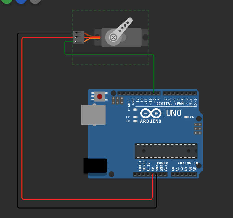
Simulating servos
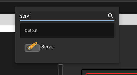
  #include

Servo esc;

void setup() {
  esc.attach(9);

  // Arm ESC (important in real life)
  esc.writeMicroseconds(1000);
  delay(2000);
}

void loop() {
  // Increase speed
  esc.writeMicroseconds(1200);
  delay(2000);

  esc.writeMicroseconds(1400);
  delay(2000);

  esc.writeMicroseconds(1600);
  delay(2000);

  esc.writeMicroseconds(1000); // stop
  delay(3000);
}
code for controlling the servo
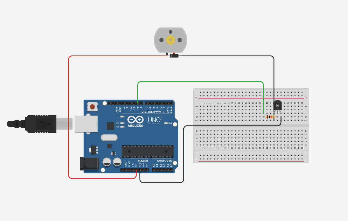
I realised that servo might not be a complete parallel to bldc, so i tried simulating a normal dc motor as well
Dc motor
wiring for the simulation
Control Side
Arduino Pin 9 → Resistor (1kΩ) → Transistor BASE
Power Side
Transistor EMITTER → GND
Motor one side → 5V
Motor other side → Transistor COLLECTOR
Protection Diode
Across motor:
Stripe side → 5V
Other side → Collector
I have switched to tinkercad now
Real test -
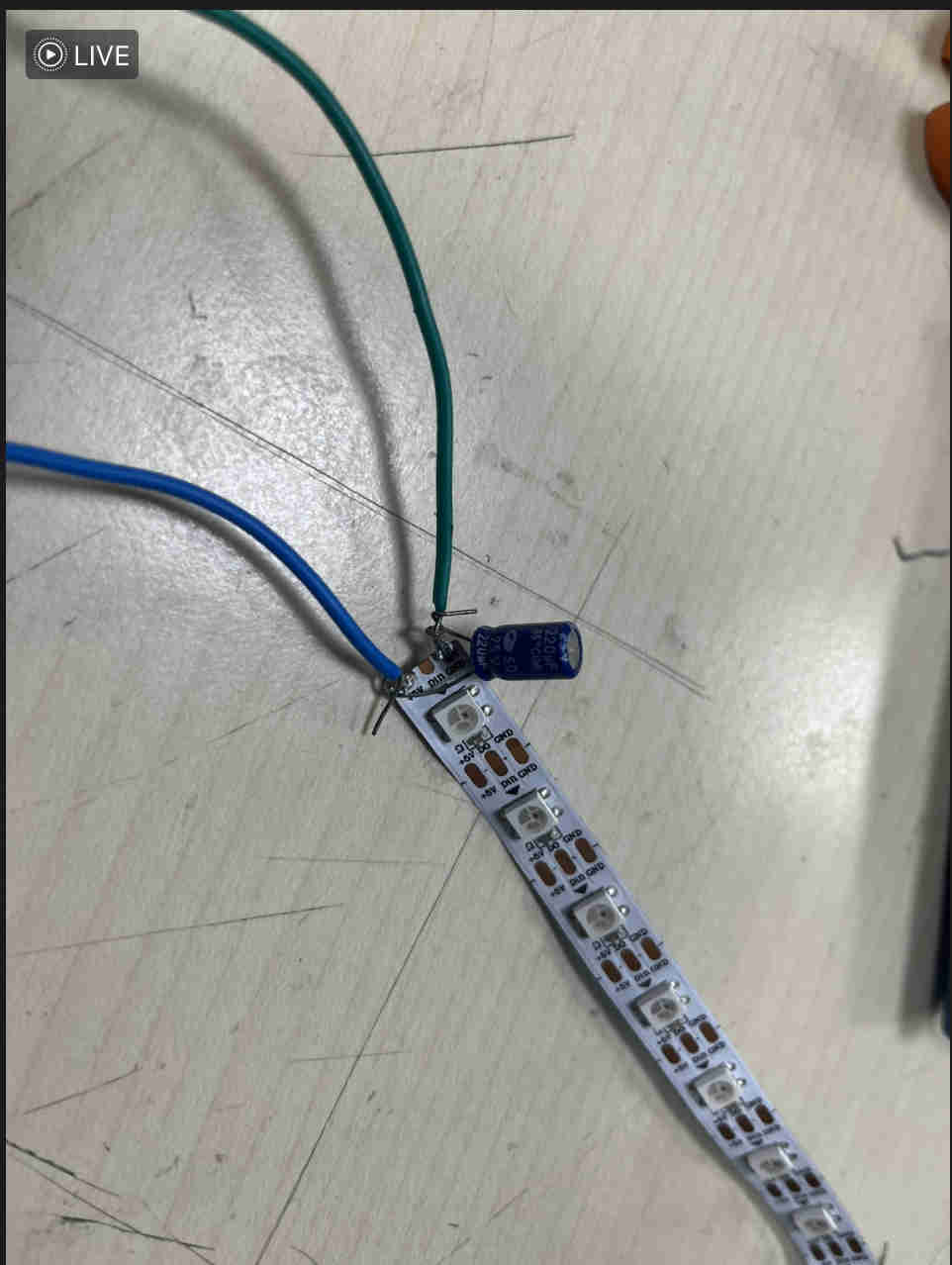
Added a 440 uf capacitor to keep the neopixels safe
DESIGNING PCB

Here is the schematic for the pcb.
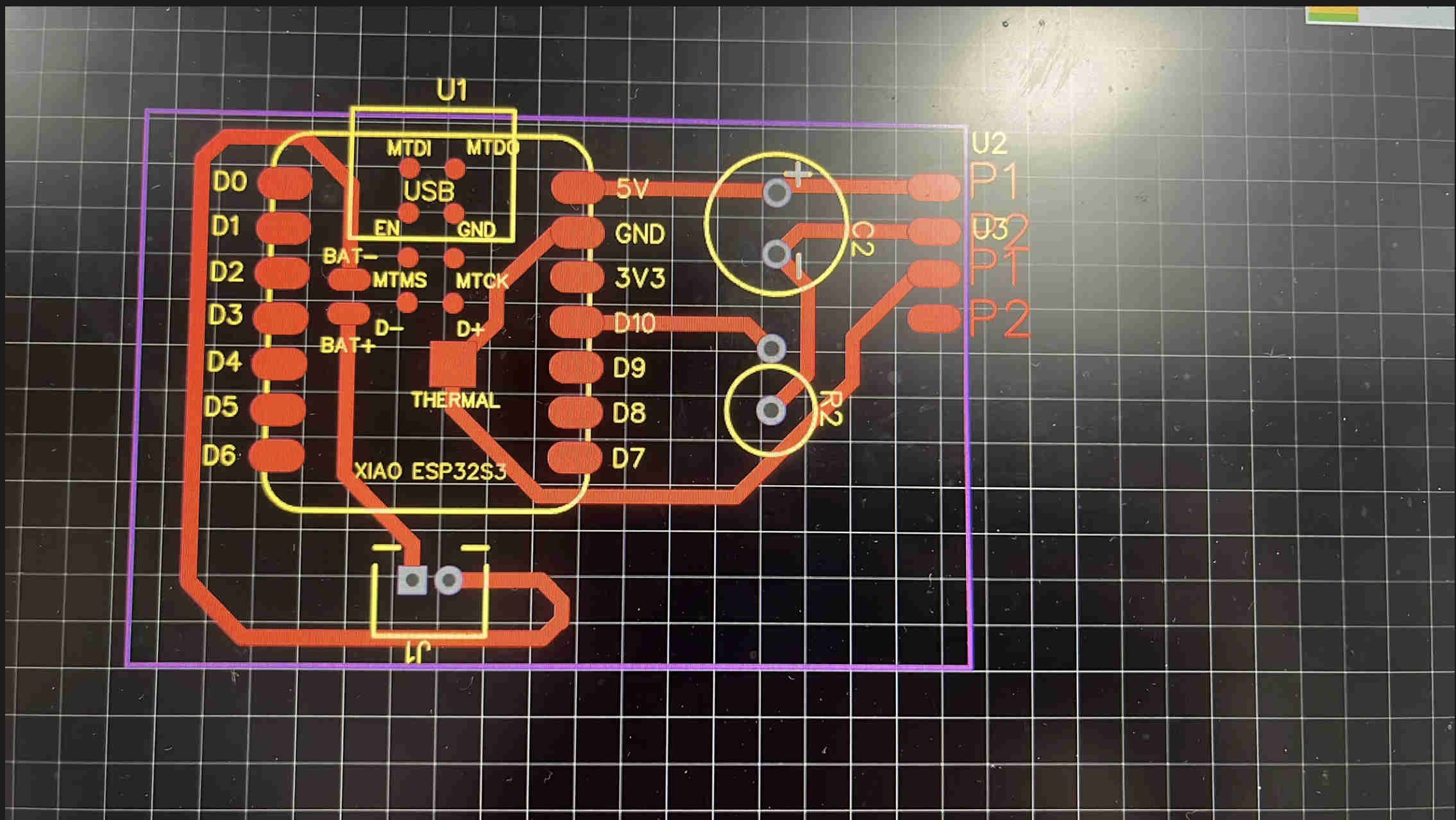
Designed a custom pcb for just neoixels. powered by a battery via a 2 oin jst connecter
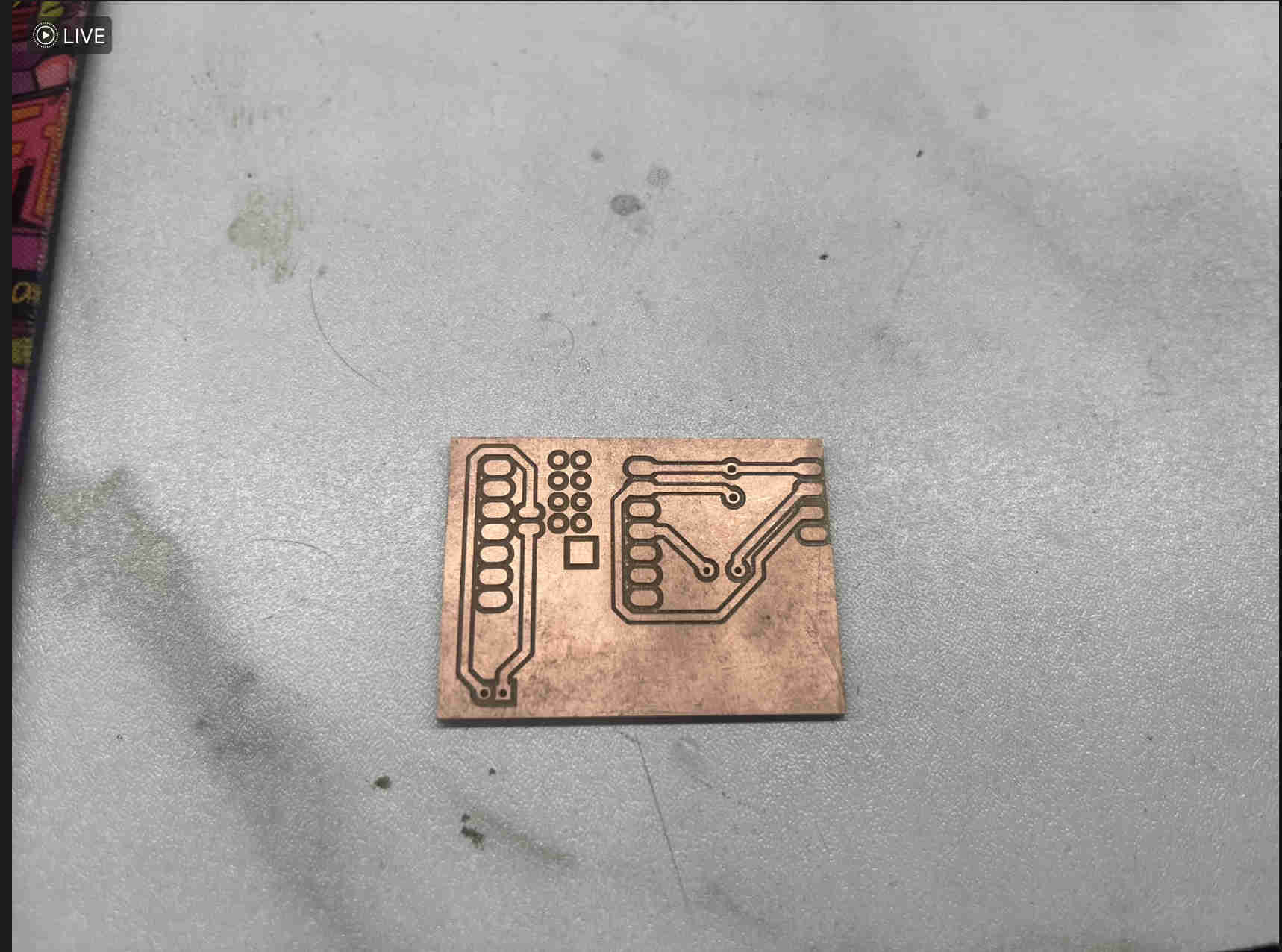
Final pcb result
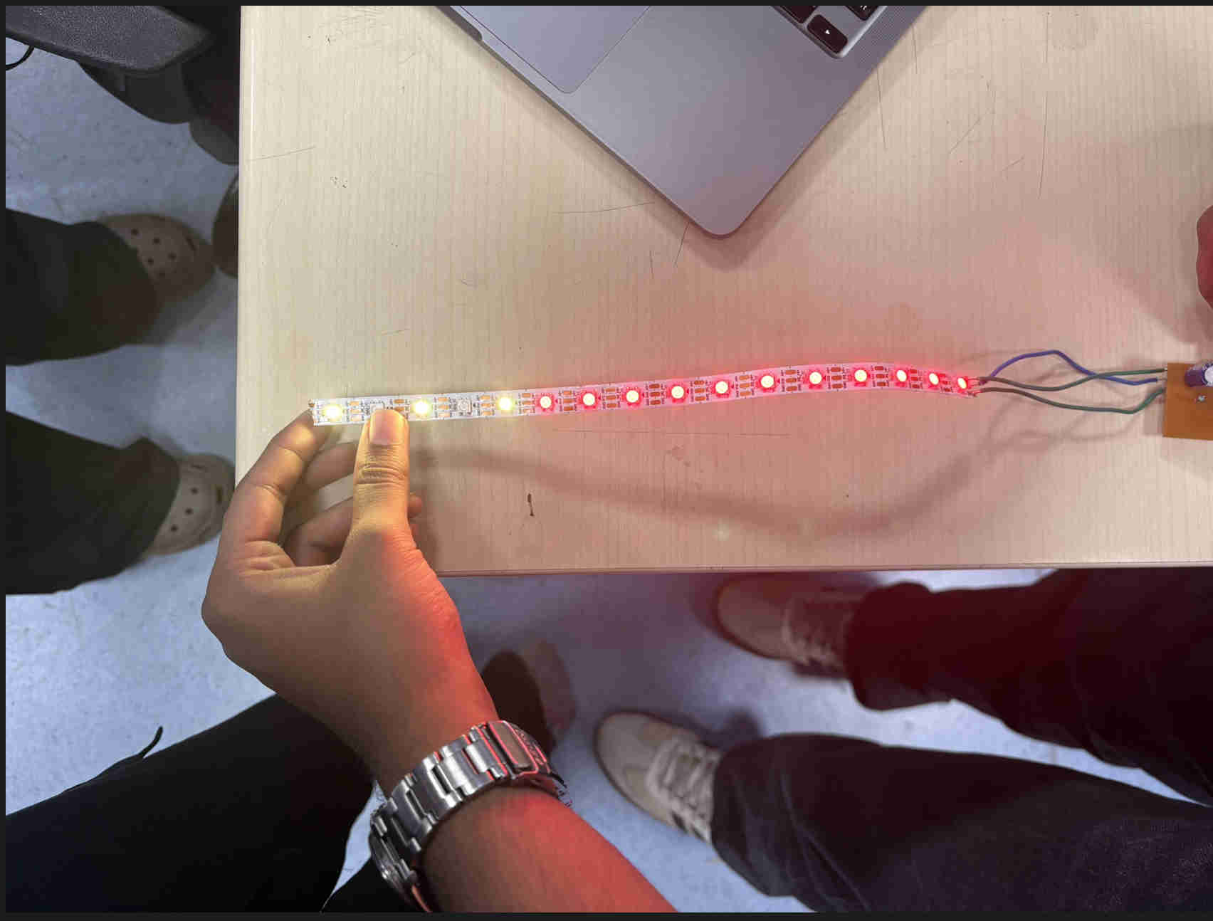
Neopixel with PCB
final result