I was quite familiar with using existing ecosytems(arduino, rasberry pi 4), but to embed prgrams directly into chips was the challenge for this week
.What is all this.
What is embedded programming?
Embedded programming is writing software that runs on specialized devices rather than general-purpose computers. These devices, like washing machines, smartwatches, or car engines, have tiny computers (microcontrollers or microprocessors) inside them that control how they work. Unlike regular software, embedded programs are designed to be efficient, reliable, and work with limited memory and power. They are written in languages like C or Python and directly interact with the hardware to perform specific tasks, like turning on a motor or reading sensor data
Microcontroller (MCU)
Microprocessor (MPU)
Processor, memory (RAM/ROM), and I/O ports integrated on one chip
Mainly contains only the CPU; memory and I/O require external components
Designed for specific embedded tasks
Designed for general-purpose computing
Low power consumption
Higher power consumption
Cost-effective and compact
More expensive due to additional external hardware
Used in appliances, IoT devices, cars, automation systems
Used in computers, smartphones, and high-performance systems
As a complete beginner i spent alot of time understanding this world and how it functions first
First we undersand different parts that one can see IN EVERY chip- types and categories will differ but they will have these
Architecture
To put it simply- architecture ISN'T a specific element of the processor, rather its how it works
Primarily the two most used architectures are- Von neumann & harvard architecture
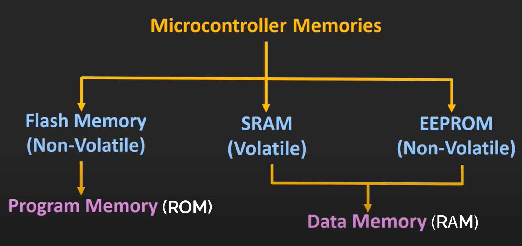
In harvared architecture there are two types of memory
. Program memory (also called program memory)- non volatile memory
. Data memory- volatile memory
https://www.youtube.com/watch?v=LTVC8KpYBI8&pp=ygUkaGFydmFyZCBhbmQgdm9uIG5ldW1hbm4gYXJjaGl0ZWN0dXJl0gcJCYcKAYcqIYzvThe above video is in hindi but explains architectures super consice
Memory
Memory is exactly how one assumes, it's what the processor stores, now this can be non volatile(does not get erased when power down). or volatile(gets erased while power down).
Primarily the two most used architectures are- Von neumann & harvard architecture
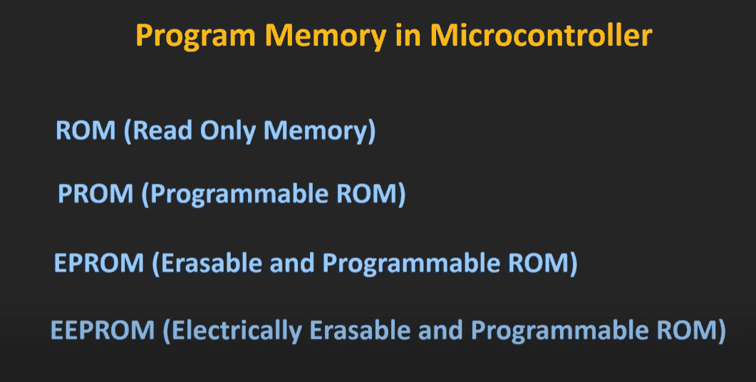
As we discussed earlier program, memory and data memory can also be classified, different types of memory as seen above are used as types of program and data memory
Remember
program memory needs to be NON VOLATILE- as program memories consists of instructions, or programs, the chip needs this data everytime
&
Data memory can be both- as data memory can be - needed when input give data or can be such that needs to be woking whenever th chip is powered on
Above show the progresion of memory.https://youtu.be/4WnTTL_7a1g?si=fM2U5NDeQOxF9lqsThe above video explains types of memory and their progression through history super cleanly.
Input and output (I/O)
Again to put it simply I/O refers to how a device interacts with the outside world.
Input: data received by a device to process
Output: Data or signals sent by a device after processing
To communicate this data- controllers and devices use SIGNALS
Signals
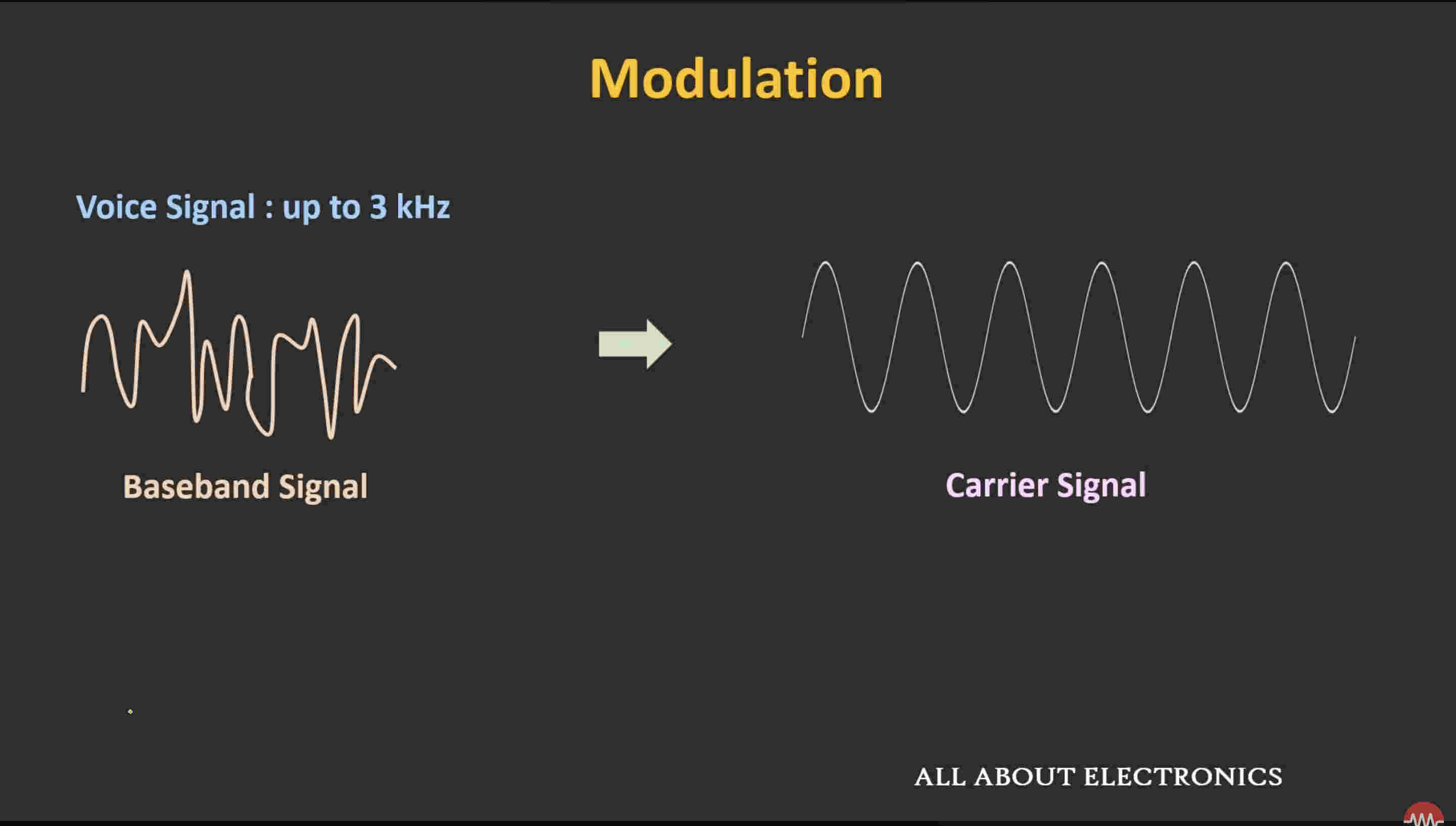
Signals are how data transmits from trasnmitter to recieverSignals at their essence, cannout be transmitted, as the bigger the baseband size of the signal, the bigger the antenna needs to be.
Thus they require MODULATION
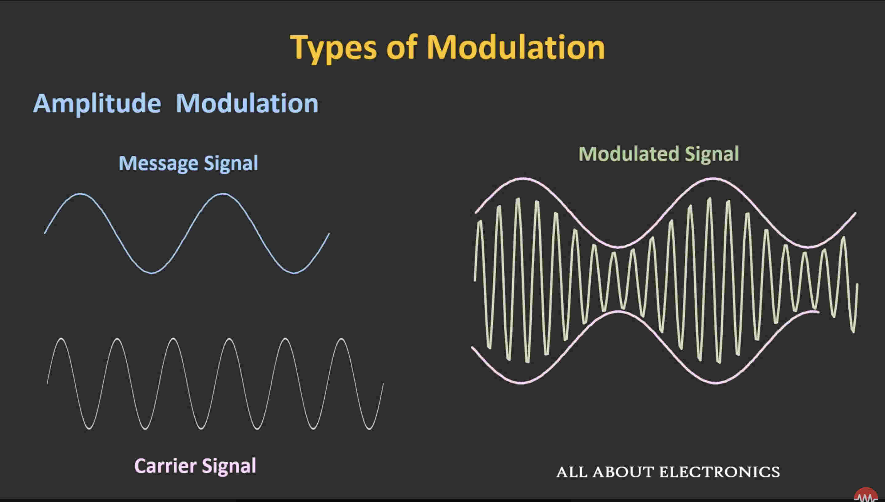
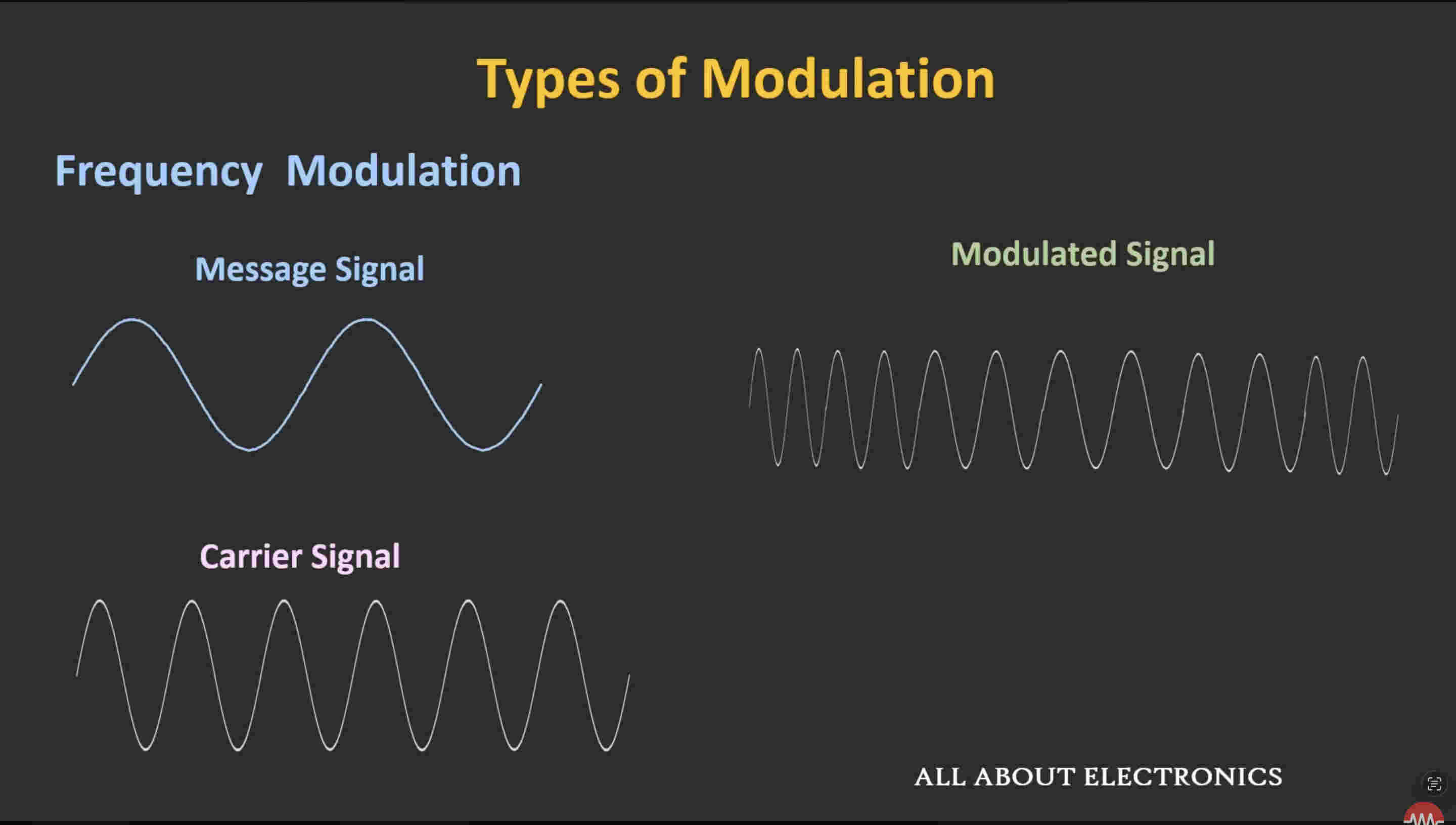
Modulation refers to the carrying of basband signal via a carrier signal to improve efficiency by reducing antenna size and reducing interfearence(refer to the link below) Above photo shows both signals, We'll disccus how exactly is it discussedThere are three elements of a signal that can be used to modulate a baseband
Amplitude
frequency
phase
You can see here how the carrier signal changes amplitude based on the mesage signal. the modulated signal(on the right) in turn has a higher frequencyThis is frequency modulation- you can see how the carrier changes frequency based on message signalThese are types of ANAOG modulationThere are also digital modulation waveshttps://youtu.be/mHvV_Tv8HDQ?si=bUvSthQrSayszlkbThe above video explains Modulation how it works and why it's needed very well.Signals sent are a form of communication, this communication has some types as well
Types of communication
Serial communication
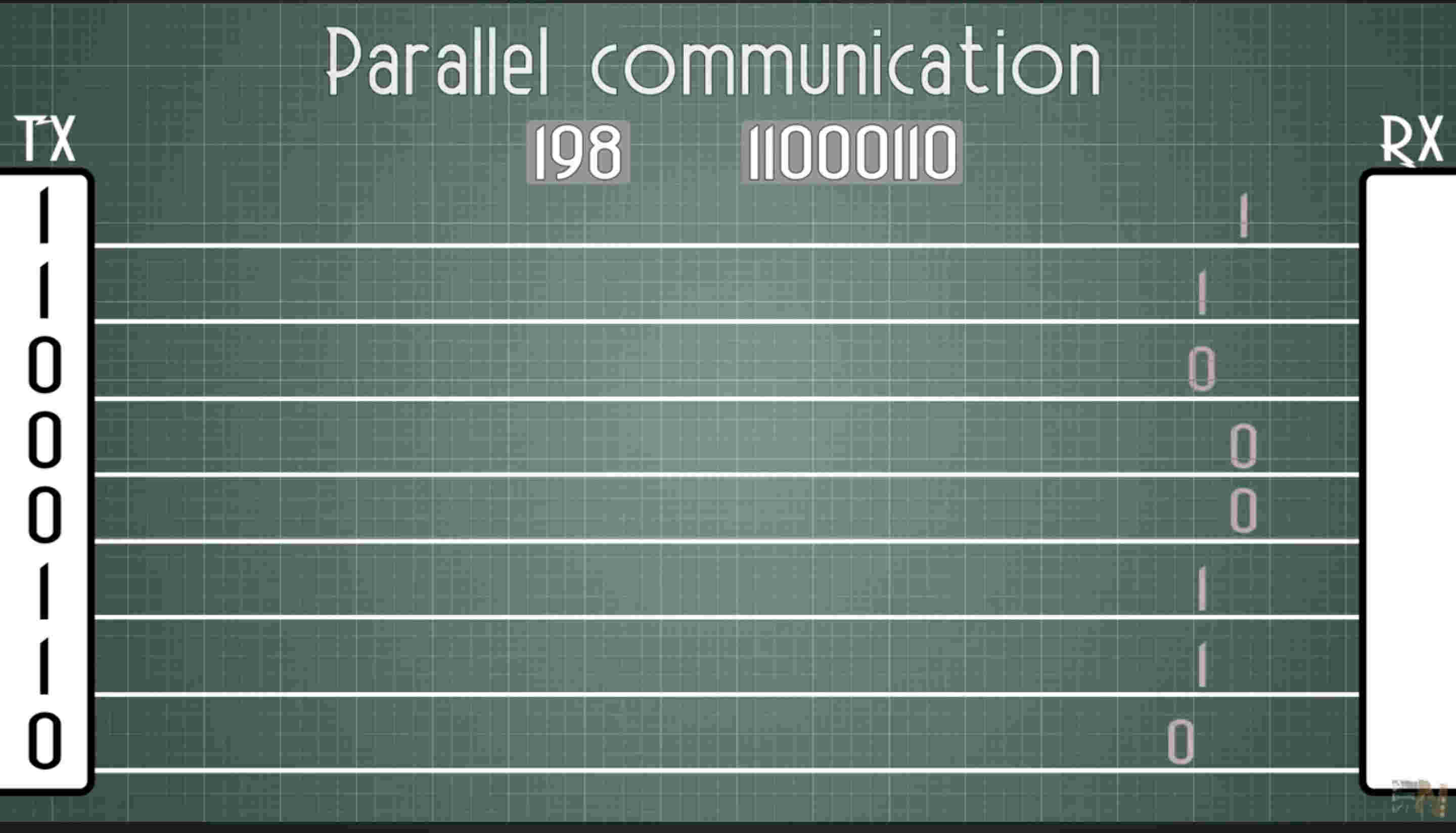
Parallel communication
This is parallel communication- each bit is being sent by an indiviudal wire so it only takes one clock speed to send a chunk of data
HOWEVER, this is 8 bit, thus there are 8 wires and a ground wire- 9 wires in total. not ideal- lesser connections are always better
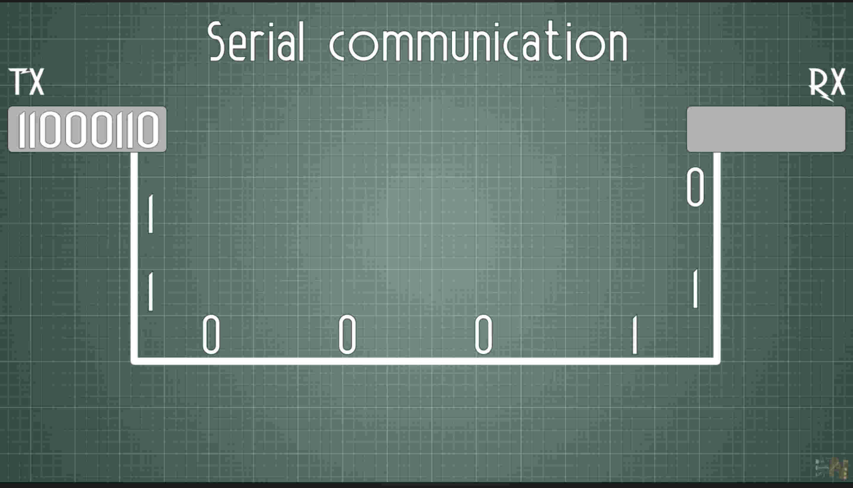
Clock is basically a unit of time in which one bit is sent. consider it in microseconds, the time taken to send one bit of dataThis is serial communication- each bit is being sent by a SINGLE wire.
The drawback to this is very evident, as seen in the image, a bit data is sent one after the other, making it 8 times slower(8 bit data) than parallel communication
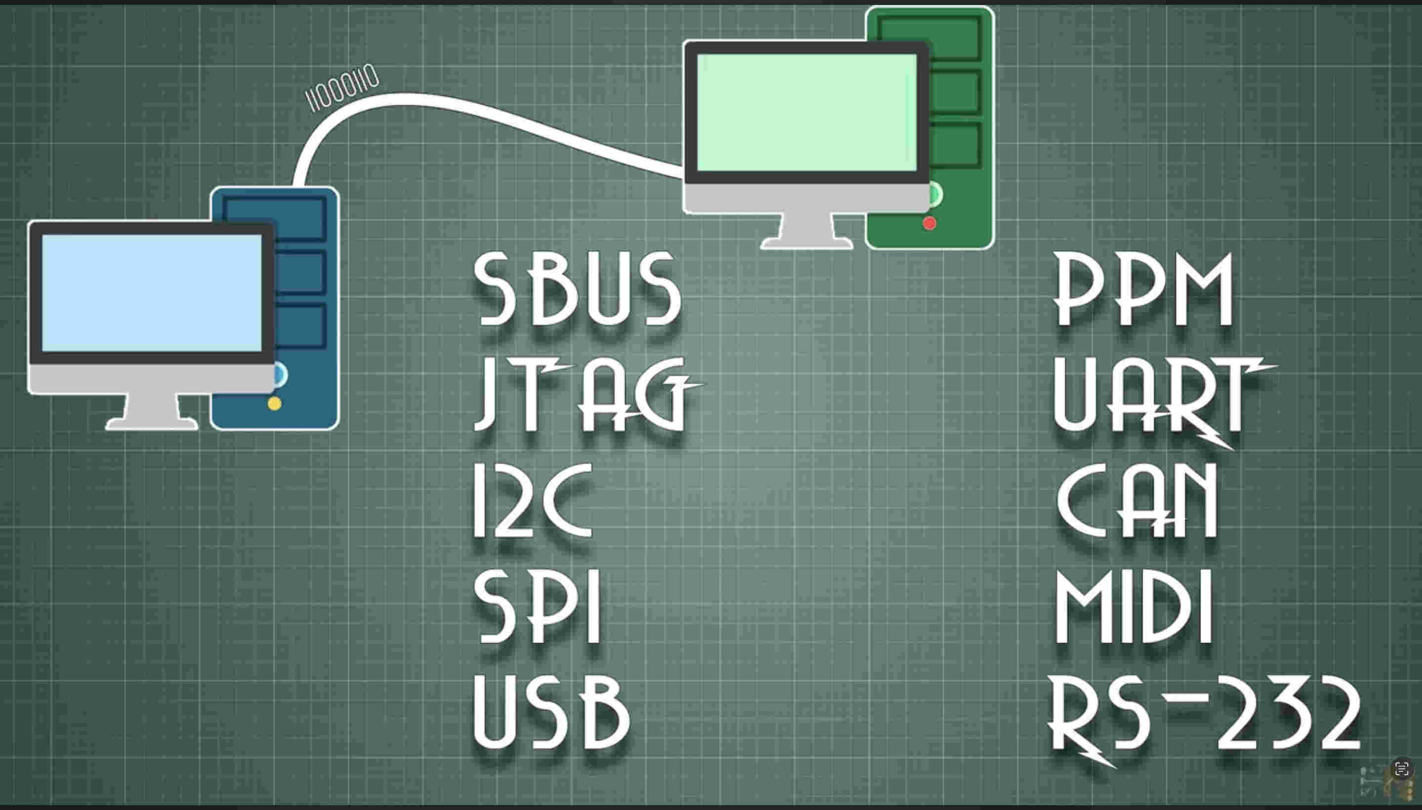
Serial communication types
There are many types of communication, some are-
We'll discuss I2C/ CAN/ SPI/ UART. in this documentation
UARTI2CSPI
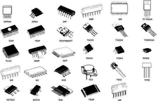
Packages
The mentioned IC and processors are sealed in a package. base fucntion of a package is to prevent damage, reduce moisture and more
These packages are of different types, based on if they are through hole, surface mount and other factors such as in line or multiside
.Group assignment. toolchains and workflows
RP2040 Development Toolchain and Workflow
Development Toolchain
The RP2040 microcontroller (used in boards like the Raspberry Pi Pico and XIAO RP2040) supports multiple development environments, making it suitable for both beginners and advanced embedded developers.
Programming Languages: C, C++, and MicroPython are the most commonly used.
Official SDK: Raspberry Pi Pico C/C++ SDK provides low-level hardware access and libraries.
Compiler: ARM GCC toolchain is used to compile firmware.
Build System: CMake is used to configure and build RP2040 projects.
IDE Options: Visual Studio Code, Arduino IDE, or any editor supporting CMake projects.
Firmware Format: Compiled programs are exported as UF2 files for easy flashing.
Debugging: Supported through SWD using external debuggers like Picoprobe.
RP2040 Development Workflow
🧩 Step 1: Setup Environment
Install Raspberry Pi Pico SDK or use Arduino IDE / MicroPython
Choose programming language: C/C++, MicroPython, or CircuitPython
Set up tools: Thonny, VS Code, or command-line toolchain
⬇️
🧩 Step 2: Write Code
Write program using CMake (for C/C++) or Python
Define GPIO, peripherals, communication, and logic
⬇️
🧩 Step 3: Compile Code
If using MicroPython: No compilation needed (upload .py script)
If using C/C++ SDK: Compile using CMake to generate .uf2 firmware
⬇️
🧩 Step 4: Upload Code
Hold BOOTSEL button and connect RP2040 via USB
Drag & drop the .uf2 file into the RP2040 storage drive
For MicroPython: upload script using Thonny or serial shell
⬇️
🧩 Step 5: Debug & Test
Use Serial Monitor (UART/USB) for debugging
Check outputs using LEDs, sensors, oscilloscope, or print statements
⬇️
🧩 Step 6: Optimize & Finalize
Optimize power consumption (sleep modes, clock tuning)
Test performance with peripherals and communication protocols
Deploy final firmware and secure memory if required
⬇️
END
ATtiny85 Development Toolchain and Workflow
Development Toolchain
The ATtiny85 is a small 8-bit AVR microcontroller used in compact embedded systems and low-power electronics. It supports lightweight development environments focused on simplicity and efficiency.
Programming Languages: C/C++ using the Arduino framework or AVR C
Core Libraries: Arduino ATtiny core or AVR standard libraries
Compiler: AVR-GCC toolchain compiles firmware for the chip
Build System: Arduino build system or Makefile-based AVR workflow
IDE Options: Arduino IDE, PlatformIO, or command-line AVR tools
Firmware Format: Compiled into HEX file for flashing
Programming Hardware: Requires external programmer such as Arduino as ISP, USBasp, or dedicated AVR programmer
Debugging: Limited hardware debugging; testing usually done via LEDs, serial emulation, or measurement tools
ATtiny85 Development Workflow
⚡ Step 1: Setup Environment
Install Arduino IDE and add ATtiny board package
Connect a programmer such as Arduino as ISP, USBasp, or AVR programmer
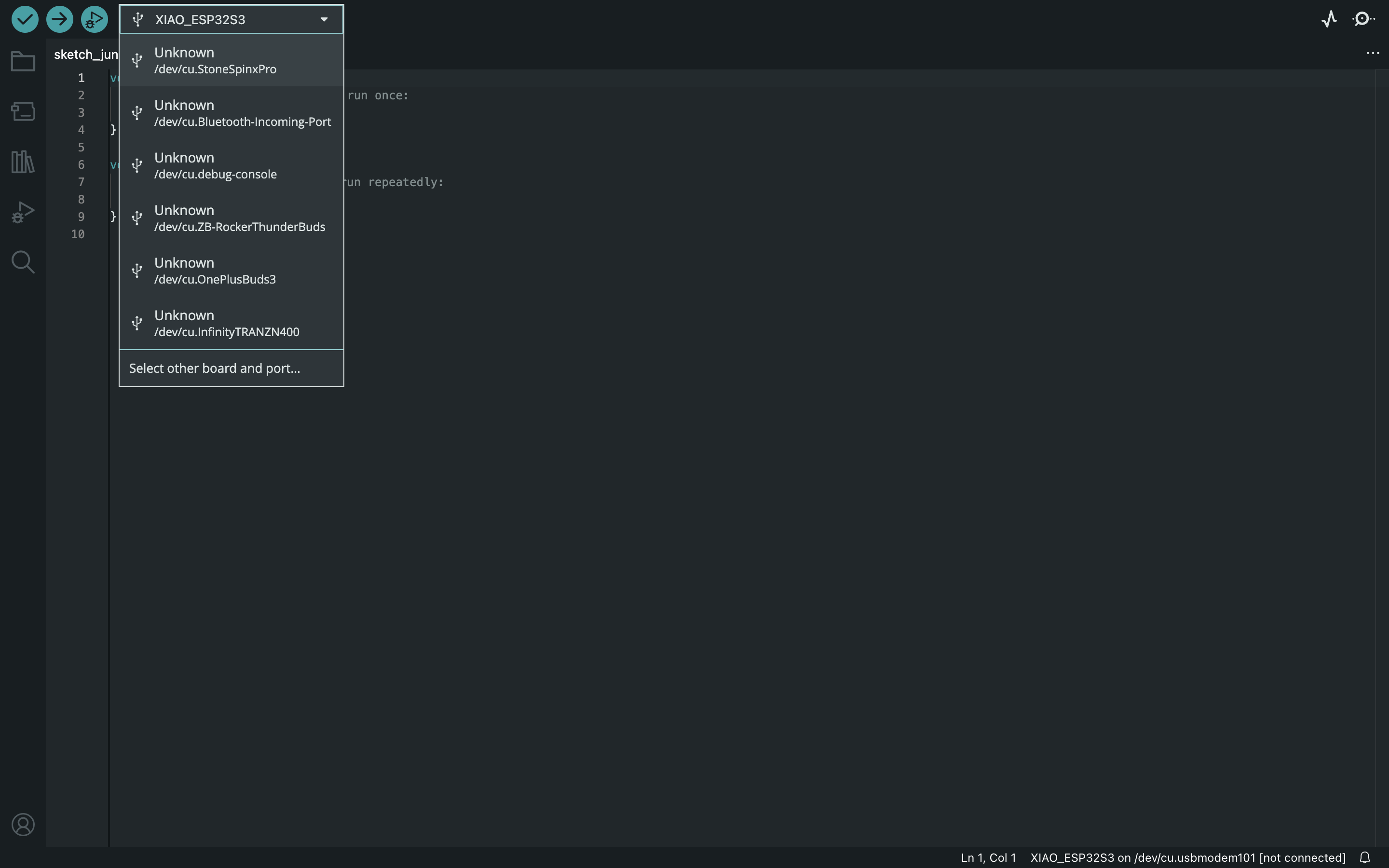
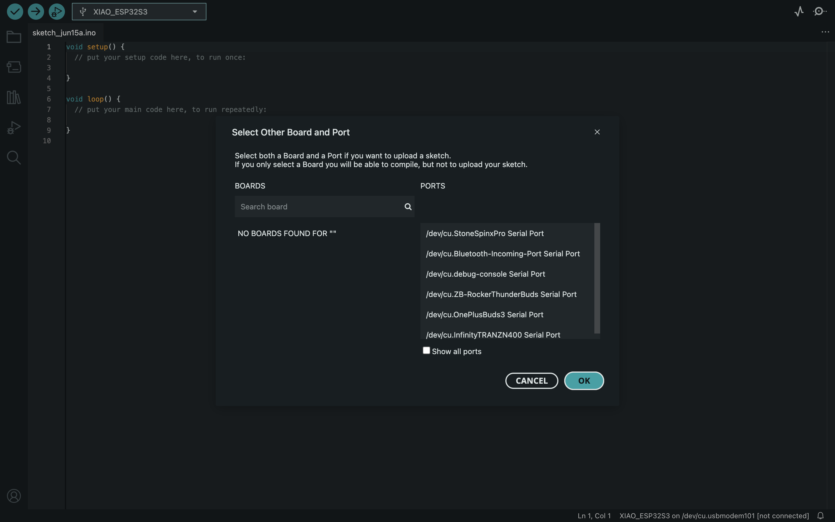
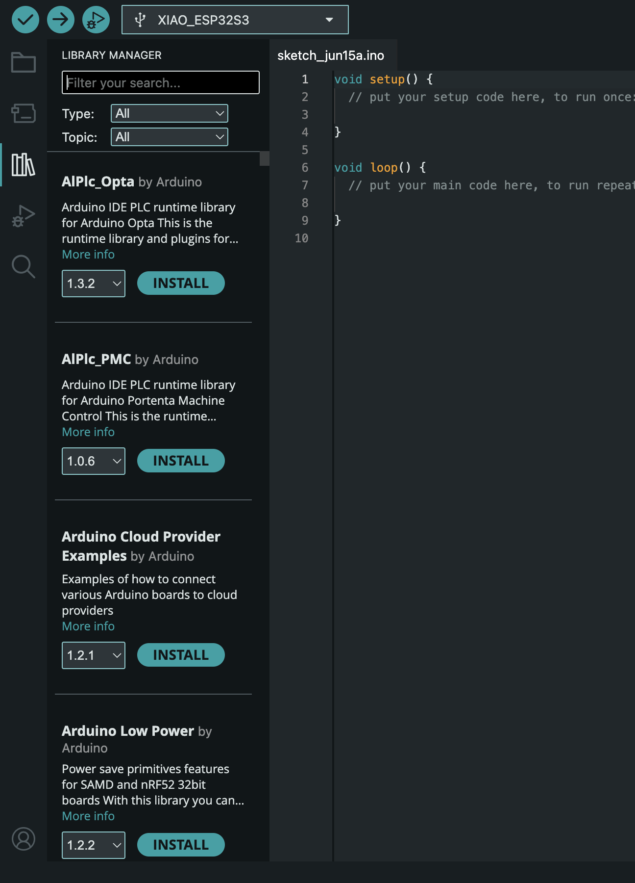
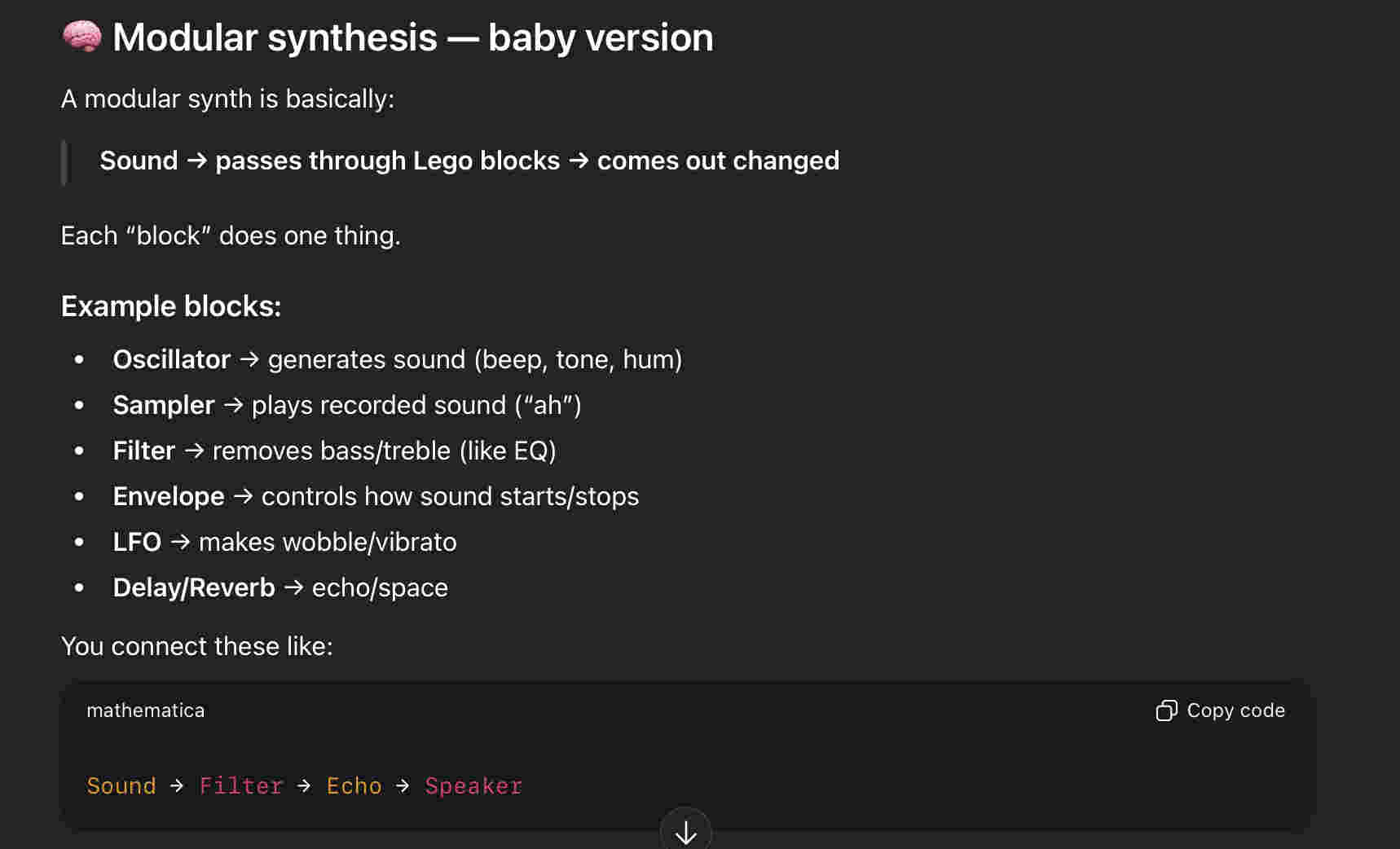
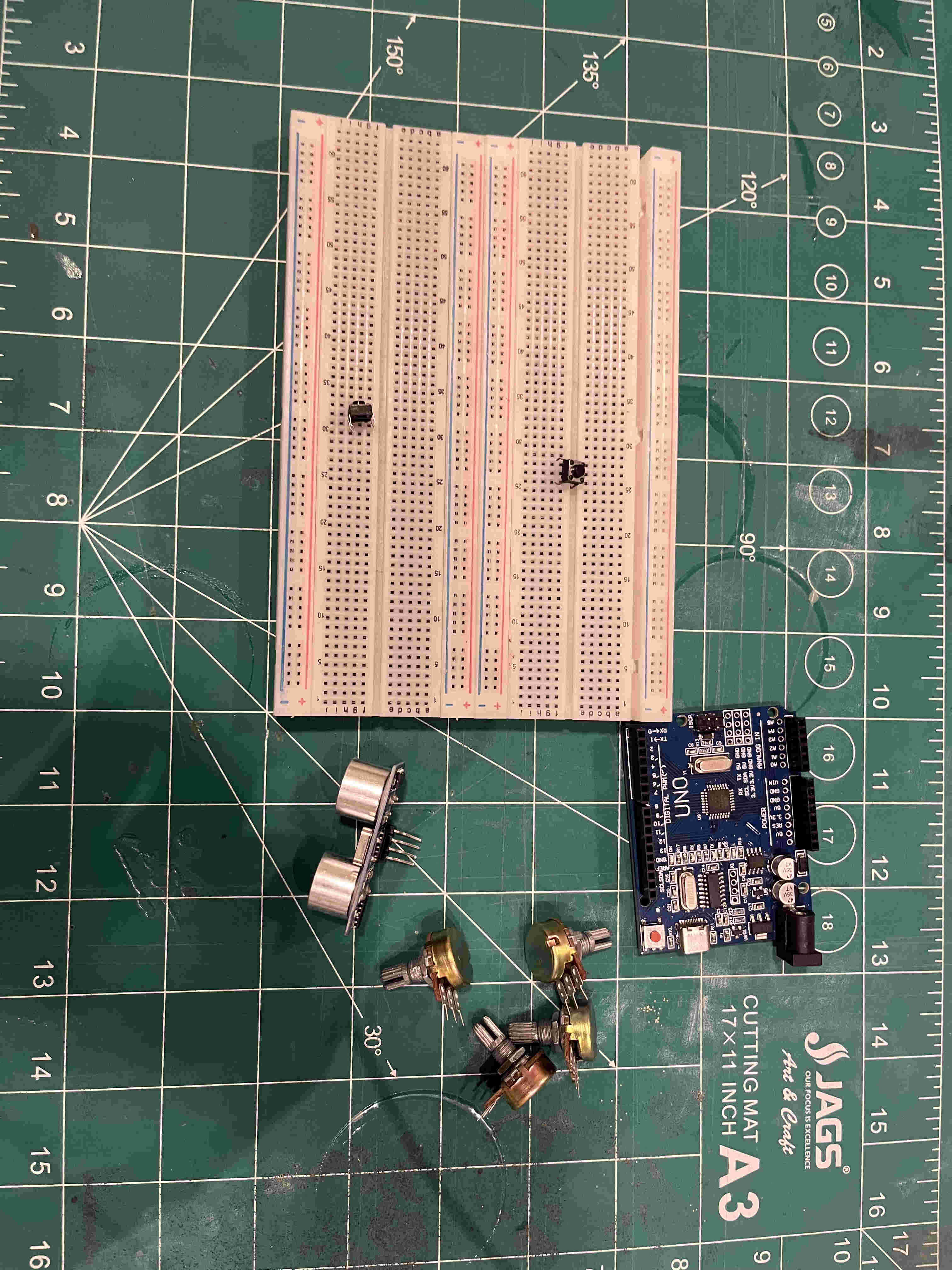
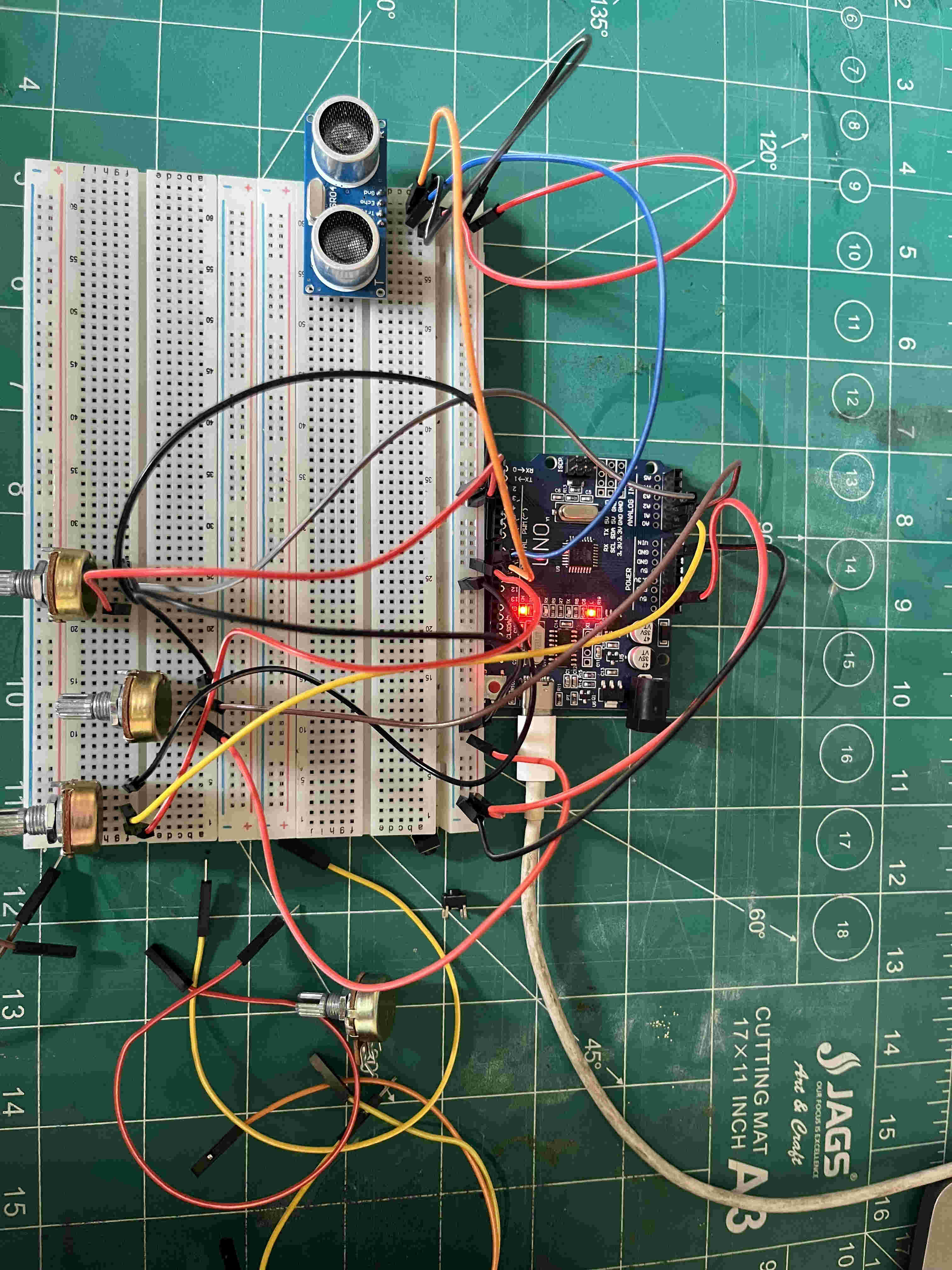
after connecting u can quick select your board port hereor you can specifically connect from here.The various code libraries canbe accessed form Here.For this week i wanted to create a gesture controlled filter synthesizer, or rather a loop stationInitially i thought we were supposed to use Ready ecosystems like the aruino uno or rasberry pi-4. later realising that the assignement comprises of using a microprocessor and create inputs and outputsI started by understanding what comprises in a modular synth and what workflow can i recreate out of the 100's of functions of a synthFor starters i picked up a ultasonic sensor for gesture and a few potentiometers and push buttons all routed to and working with arduino unoMy plan was to-
Take audio input from a mic, interpretted by a rasberry pi-4,
Take gesture input from a controller connected to an arduino uno
Finally output synthesized audio using rasberry pi-4
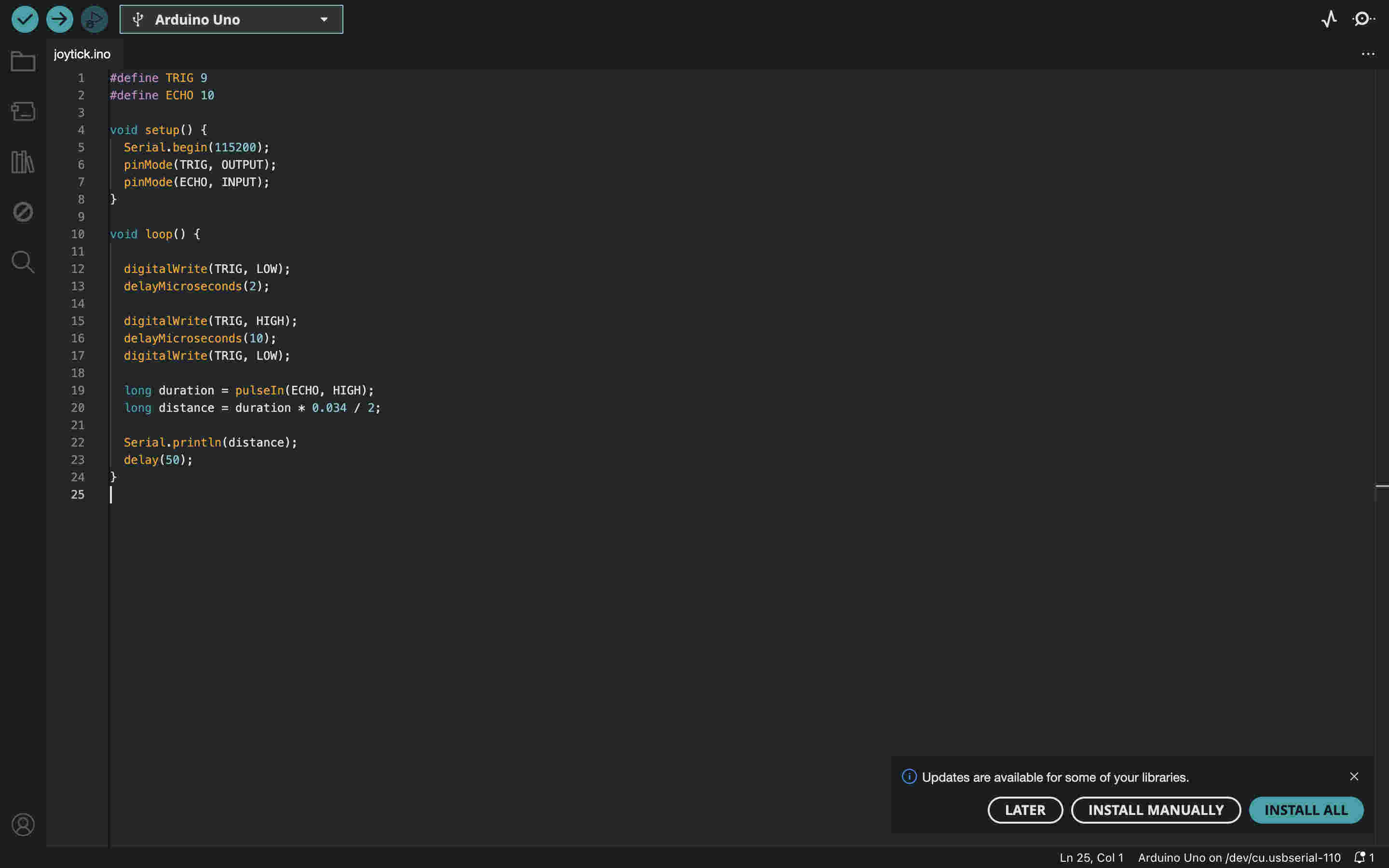
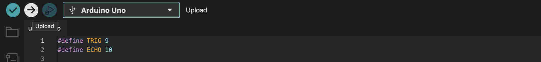
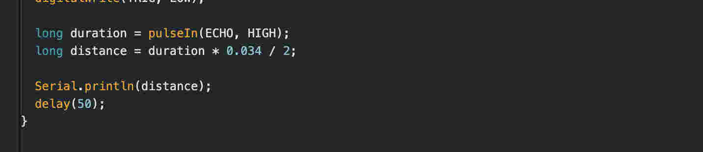
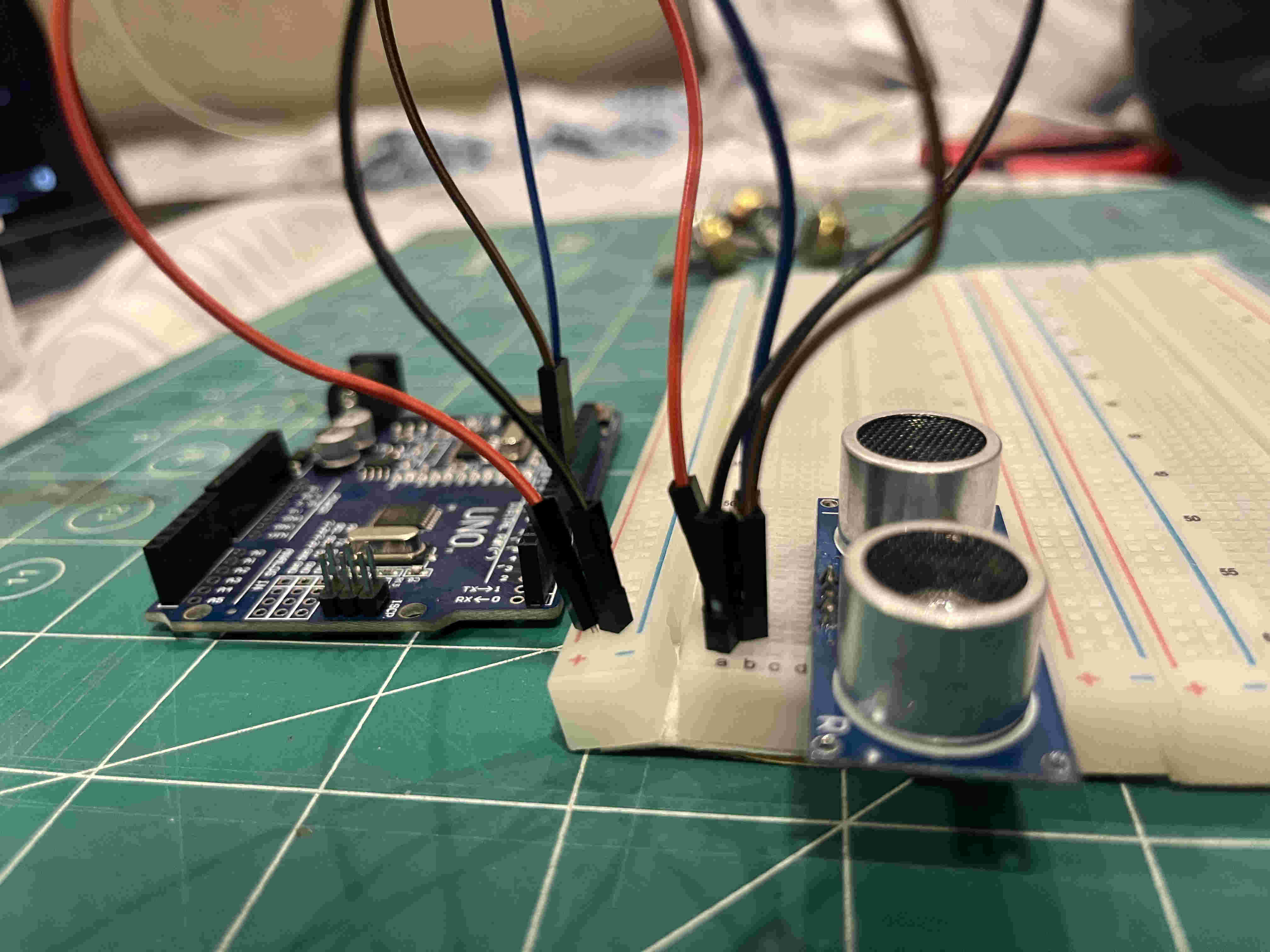
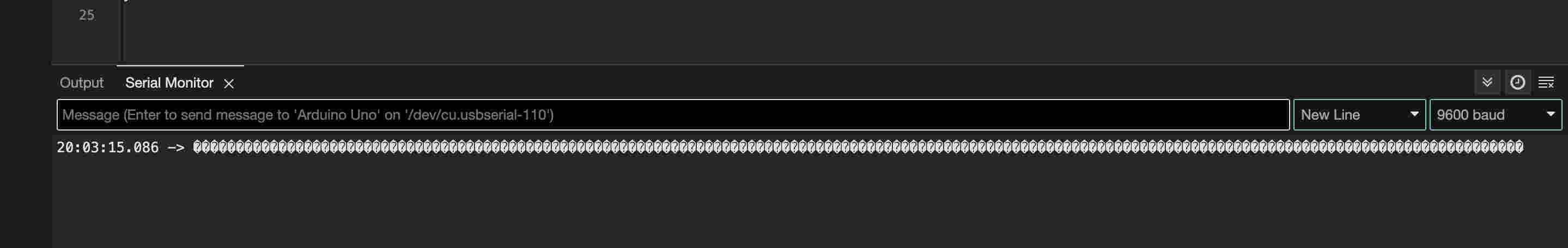
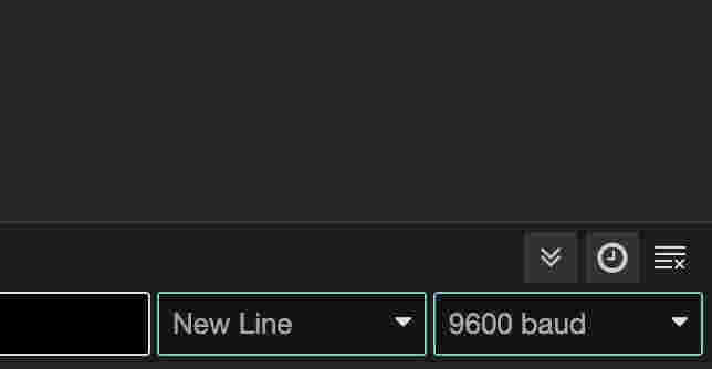
Wrote a basic code to read distance using a hc_204 sensor- and display the caluculated value on the serial monitor(ide)Defined my connectionsAbove is the formula to get a calculated distance by using data interpretted by the sensori wired my sensor on my board as seen When i ran the code i saw nothing on the serial monitor, The culprit was my baud length definition. As we discussed earlier, in an asynchronus communication, baud length and a few factors have to be defined in order for the signal to be interpretted correctly. The baud code in my code is 115200, whereas in my serial monitor it is 9600 I set up the entire controller with 3 potentiometeres for pitch and gating sound and a distance meter to get another input
Right about here i realised this is not the requirement for this week(╥﹏╥)
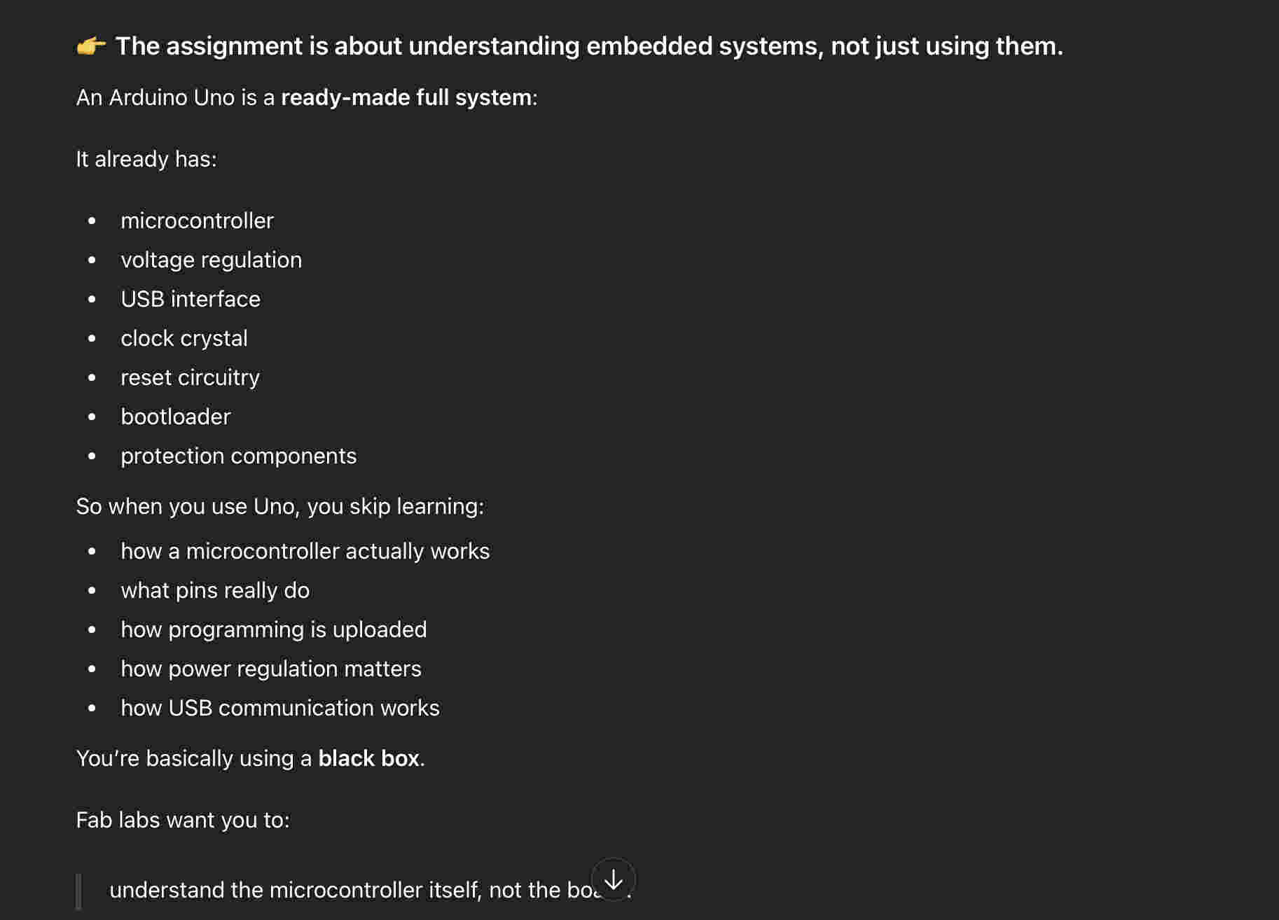
.Individual assignemnt. (the correct way)
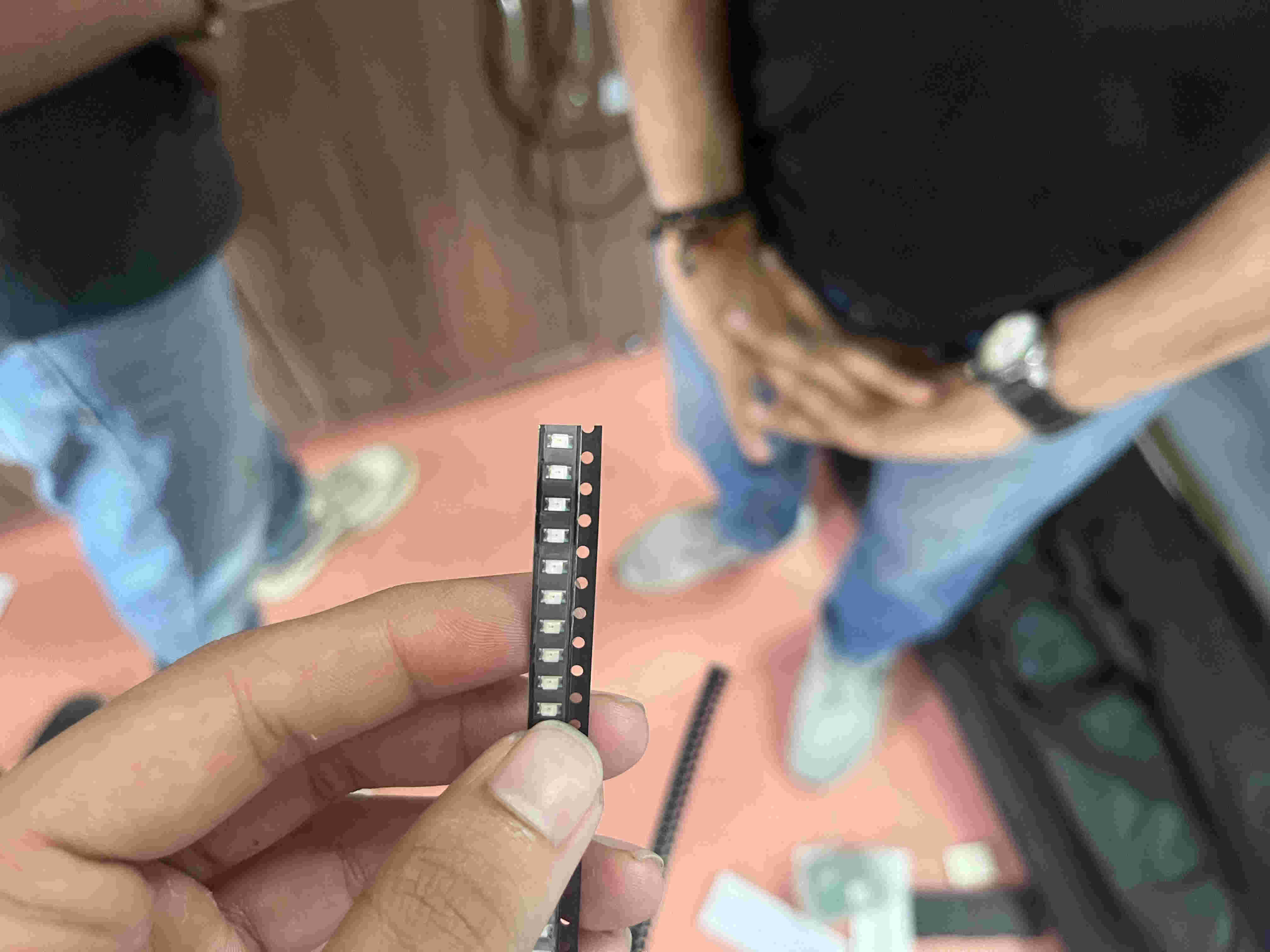
When i was told that this is incorrect i was confused as to why a microcontroller could not be usedThis explained things a lot betterfirst i took some time understanding smd components. i was familiar with through hole pcb but did not know much about smd connections
Above pic is an smd led. the terminmals are shown by the small green dots on one side and none on the other
I revisted the recitation to understand setup and basic fundamentals.
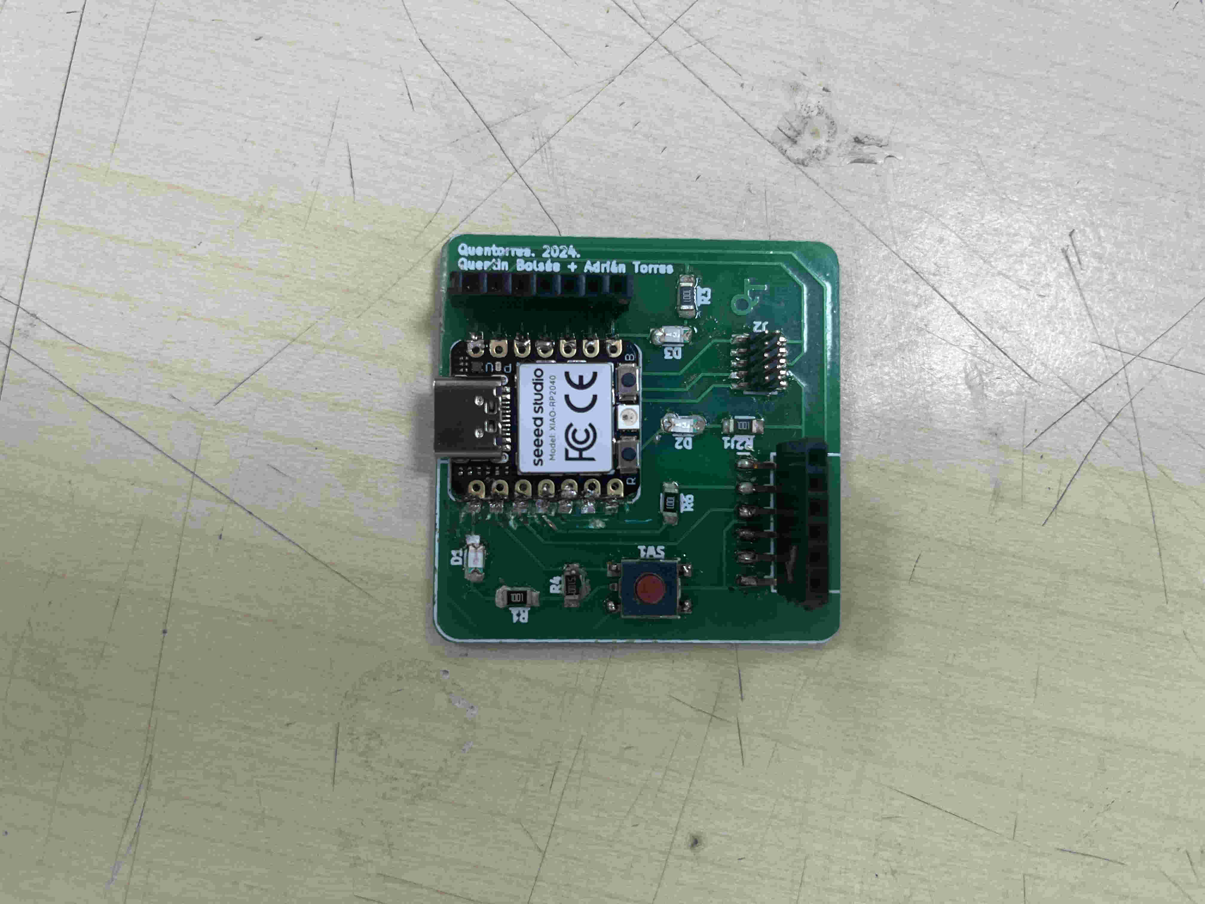
The board i started with was a Seeed xiao rp2040. this was already pre built on a quentorres board by the previous years fab academy batch.
I planned to solder my own one after understandind the how's and who's of this board
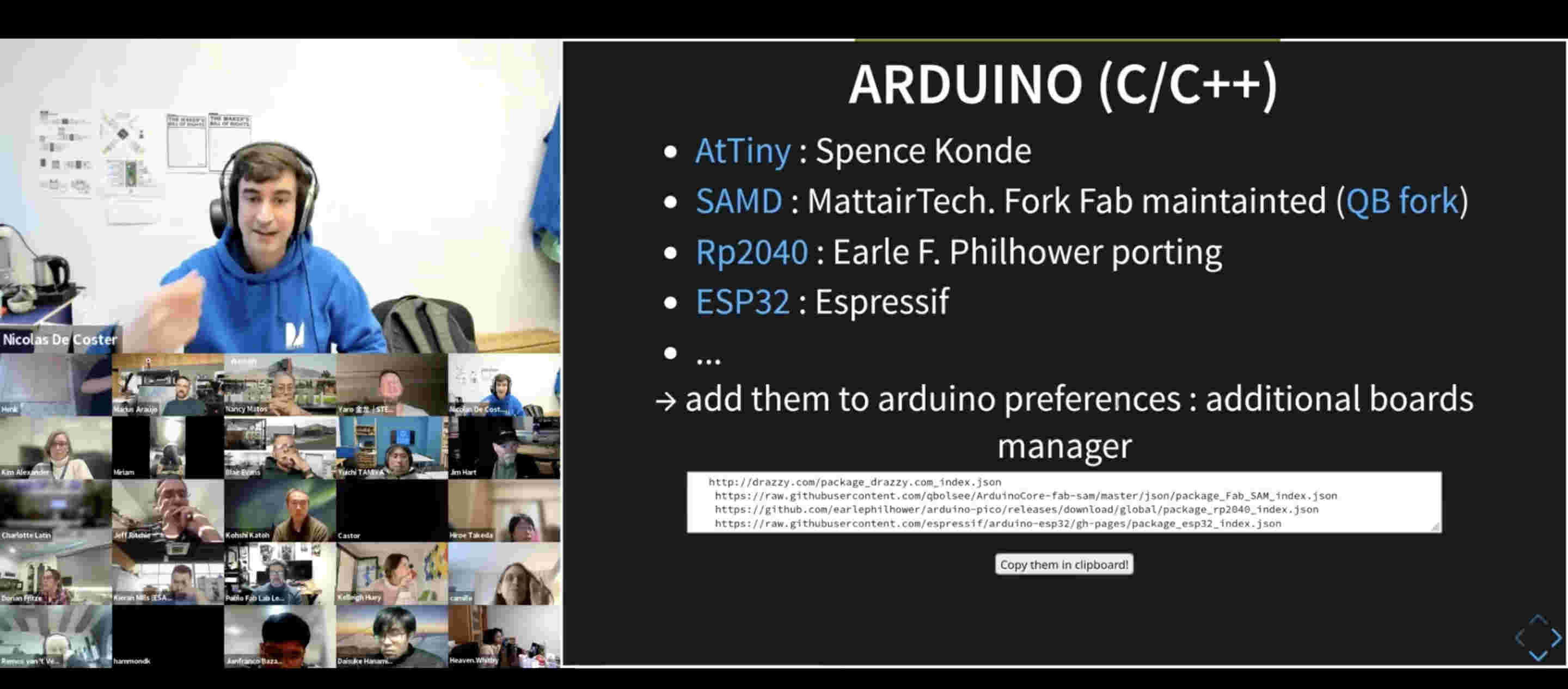
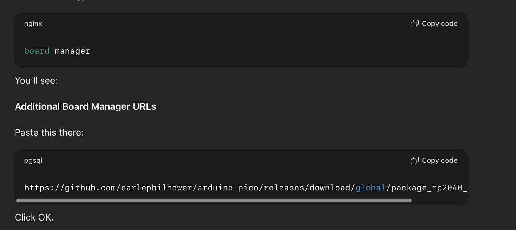
First step was to add the board on my arduino IDE
steps-
open IDE
Go to tools on the top menu
open boards- board manager
paste ths url given below
https://github.com/earlephilhower/arduino-pico/releases/download/global/package_rp2040_index.json
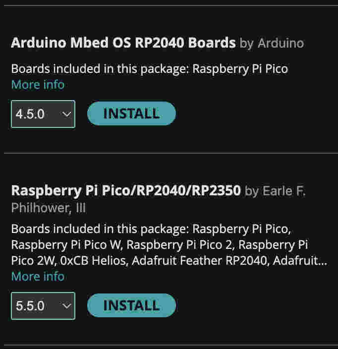
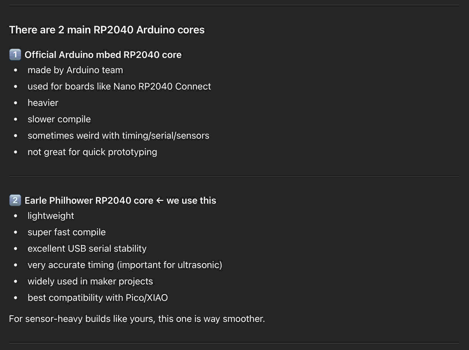
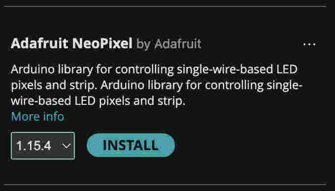
Next step was to install a library.
However there were 2 similar libraries by two different creators
Quick gpt search revealed why the earle phillhower one is better.
Next i connected my xiao using bootloader mode
How to bootloader mode-
long Press the small black button on the right side of the led on the xiao
while pressing connect the xiao using a type c cable
hold for 2 seconds then release
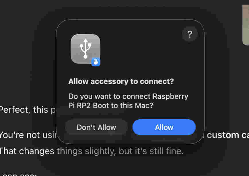
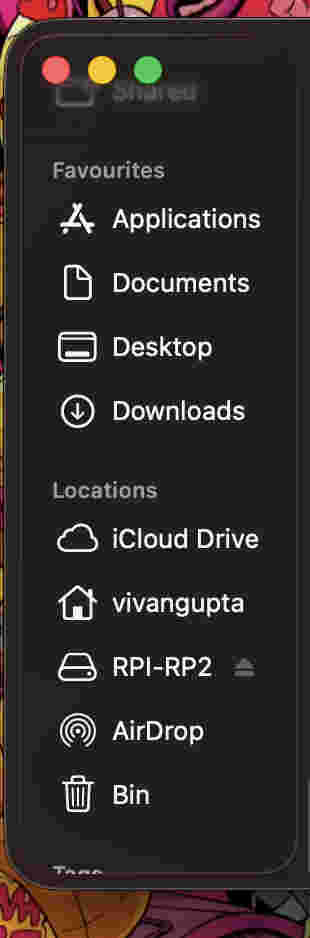
Once you insert it in bootloader mode a drive should appear on your finder.
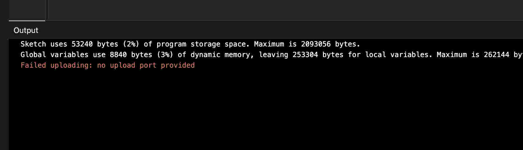
Despite the board being connected, I could not upload any file to the xiao using IDE.
Sometimes on a mac OS, it becomes tough to communicate to a xia. In this scenario xiao has a slightly more tedious but reliable process where one can directly upload UF2 files to the rpi- drive seen on finder.
Mac OS turned out to be super duper tedious for this particular week. Use a windows for this week if possible(╥﹏╥)
Steps to upload on your xiao the brute way
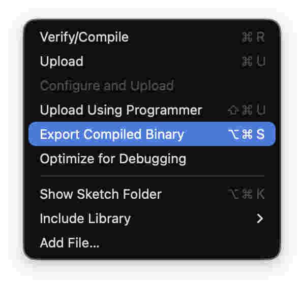
Once your code is Ready-
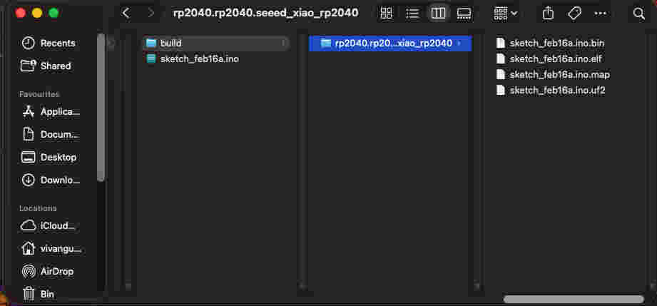
Go to 'sketch' in the top menu and select export compiled binary.
wait for compile complete statement on your IDE
Then click on show sketch folder
Your finder will open,
Drag and drop the. UF2 file onto the rpi drive
I spent alotttt of time trying to figure why my neopixel wouldnt glow.
Only to realise that that ISN'T the neopixel, the neopixel is on the right side of the type-c port.
Even after that i could not control the BUILT_IN LED- for which i used an array code
This was my first succesfull trial- lighting the built-in neopixel led at an interval of 500ms.
To control the neopixel on the xiao you will need to install a library- Adafruit neopixel~ by Ada fruitThis wasn't easy - I did not know which chip pin communicates with the built in led.
To solve for this I used an array program
Basically I made an array of all pins numbers, then ran a code that give a HIGH signal to turn on the led. i gave a second of interval between each signal. So post every push of program- i started counting seconds. around the number of seconds at which the light was on was the corrrespondent pin
This gave me the pin which i then coded for.
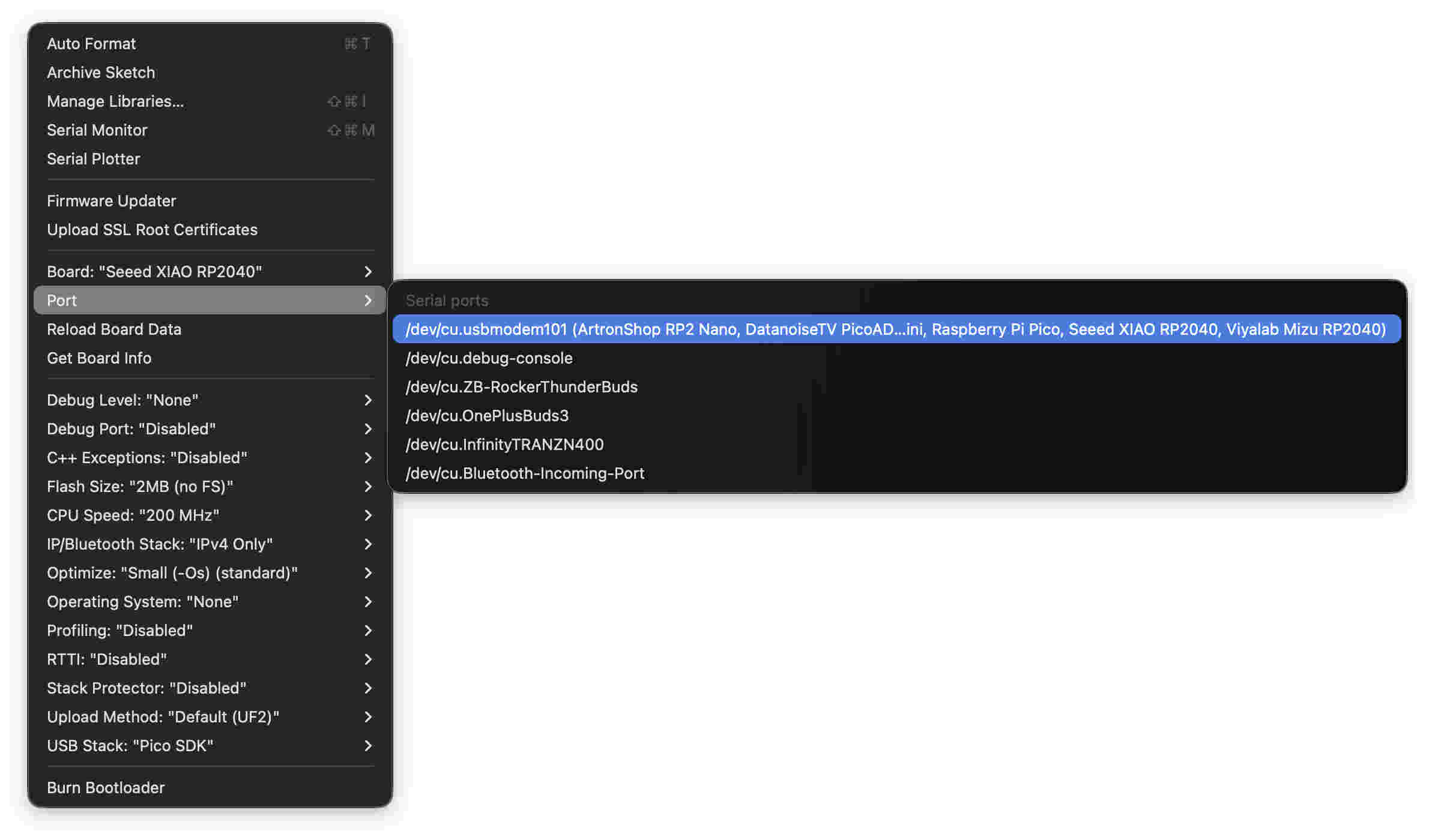
Once you have uploaded your file the brute way- your IDE might start reading the board to communicate directly via IDE. open Ide and check port under tools and find anything that saye
/dev/cu/usbmodem101...........
You will be able to send code directly with less hassle now.
Simulations
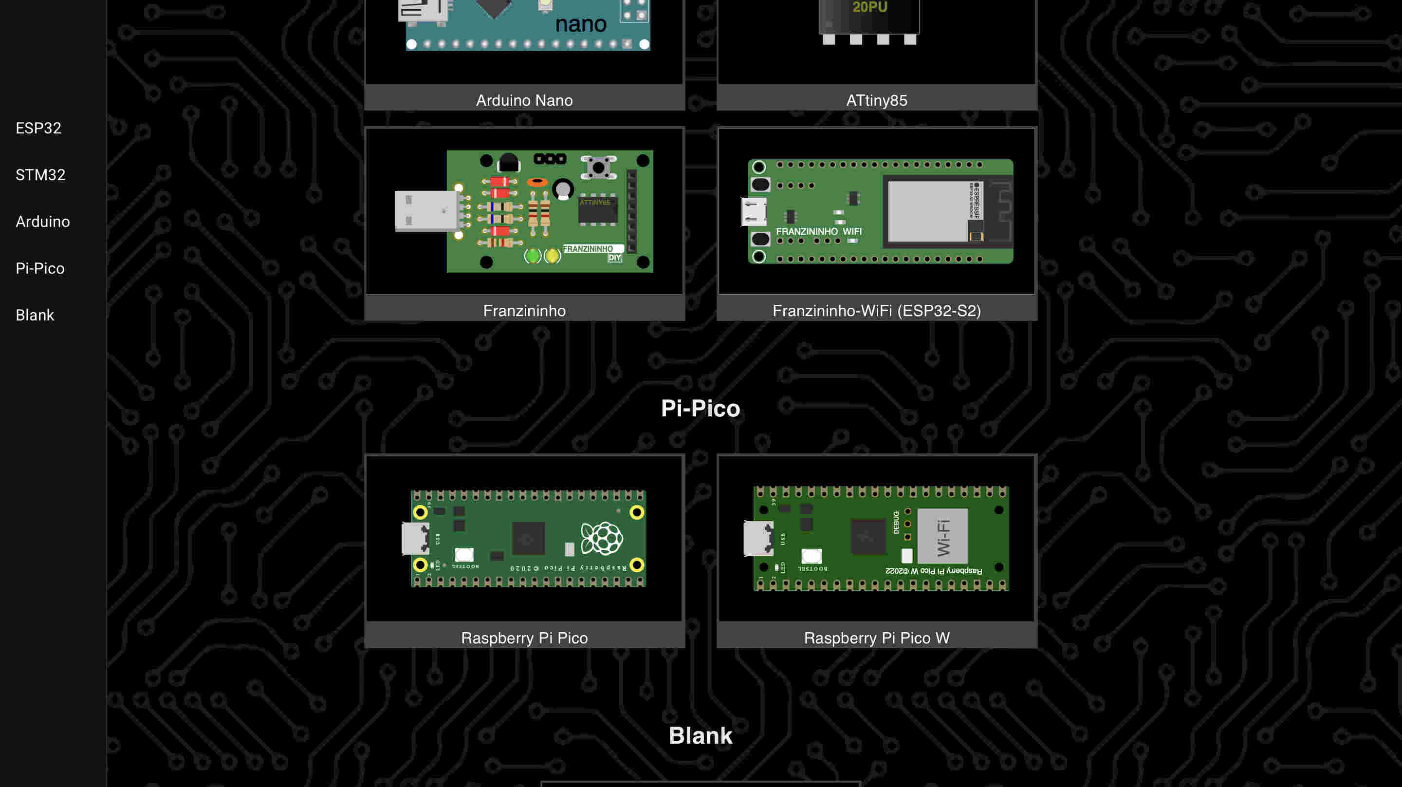
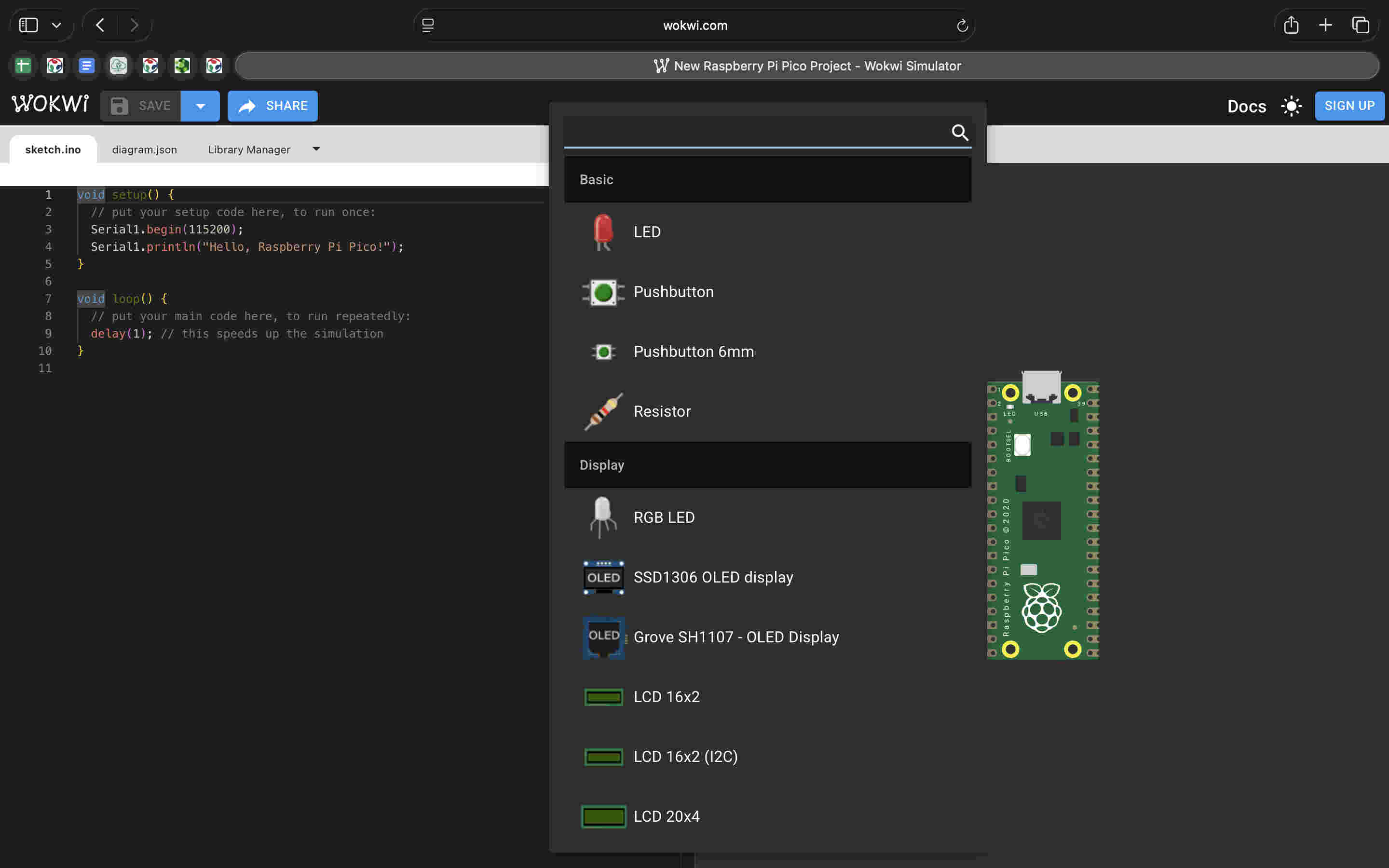
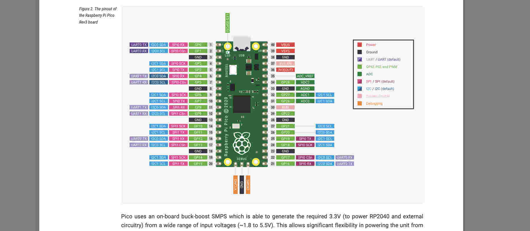
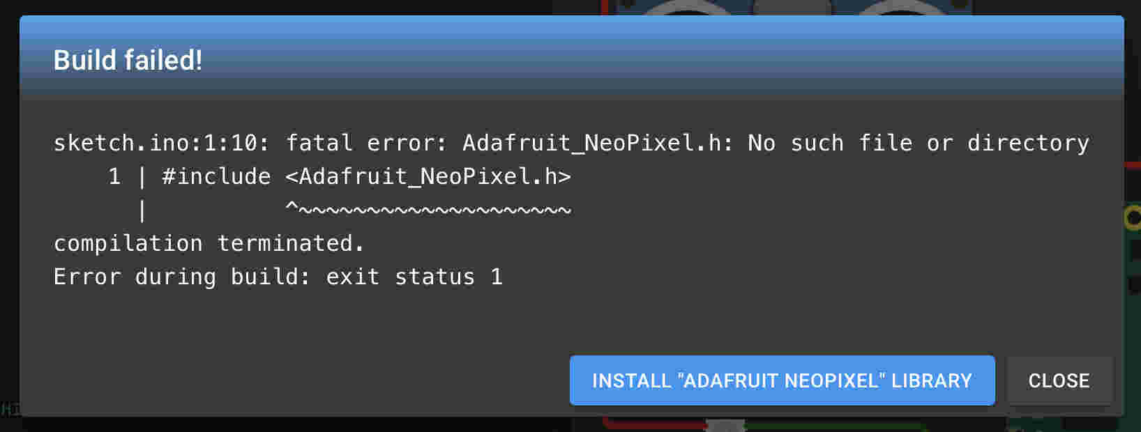
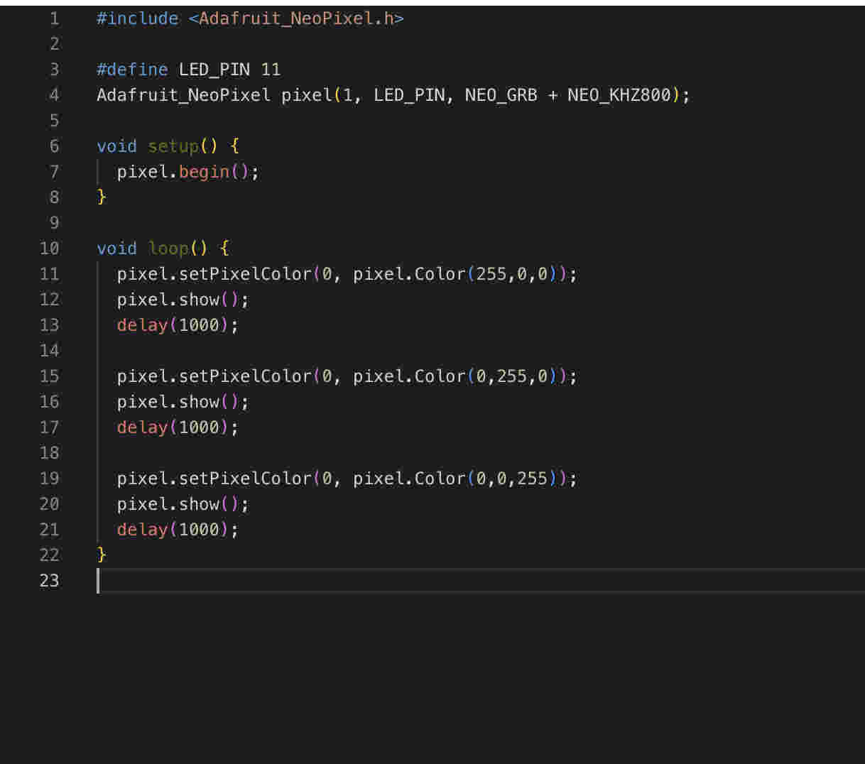
Instead of spending my time on wiring and then figuring whats wrong, which was hindering my understanding of code itself. I decided to start simulating thus I could focus on code and build some confidence I had tried easy EDA before so this time i tried Wokwi.https://wokwi.com/For Rp2040- we use rasberry pi picoI started refering to the pi pico datasheet- for understanding pin numbers- power output values and morehttps://pip-assets.raspberrypi.com/categories/610-raspberry-pi-pico/documents/RP-008307-DS-1-pico-datasheet.pdf?disposition=inlineSchematicBy clicking on the plus sign on the right side we can start adding parts- here we add are WS812 neopixel.Remember to add libraries here too, adafruit needs to be installe din simulations as wellThis was the first trial code for an external neopixel that i connnected to pin number 11 of the board
In the code i am alternating between red/green & blue with a delat of 1000 miliseconds. all of this is in the loop function so that it keeps repeating
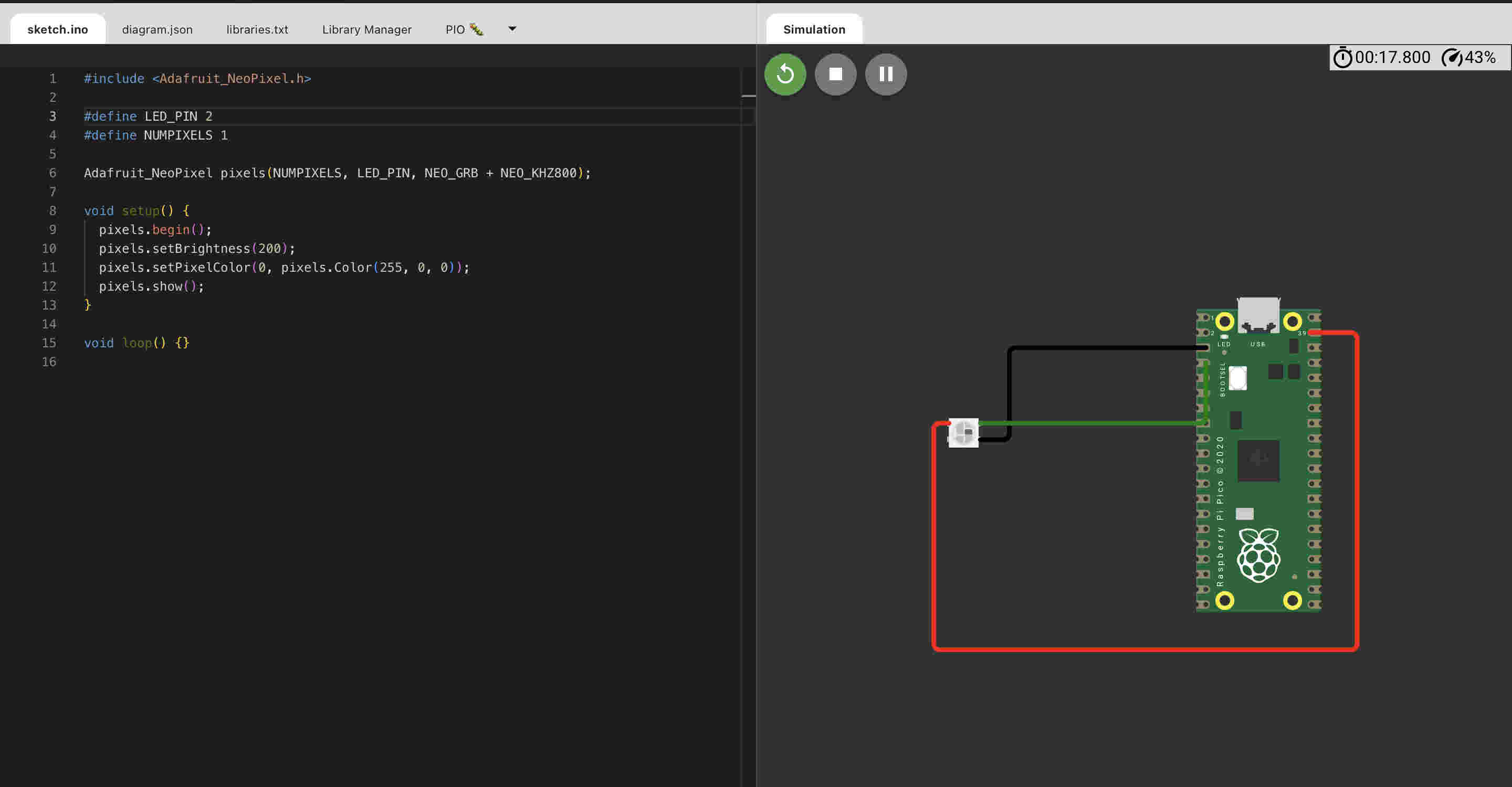
Failed(╥﹏╥)(╥﹏╥)(╥﹏╥)(╥﹏╥)(╥﹏╥)(╥﹏╥)(╥﹏╥)(╥﹏╥)(╥﹏╥)I took a step back and tried only one solid colour at the start of the code(setup). so the result should be a bright red glow on the led when i start the simulationFailed Again(╥﹏╥)(╥﹏╥)(╥﹏╥)(╥﹏╥)(╥﹏╥)(╥﹏╥)(╥﹏╥)(╥﹏╥)(╥﹏╥)When nothing worked I tried to switch browser as that is the only link left to make things not work was the browser.
Still didnt change anything(╥﹏╥)
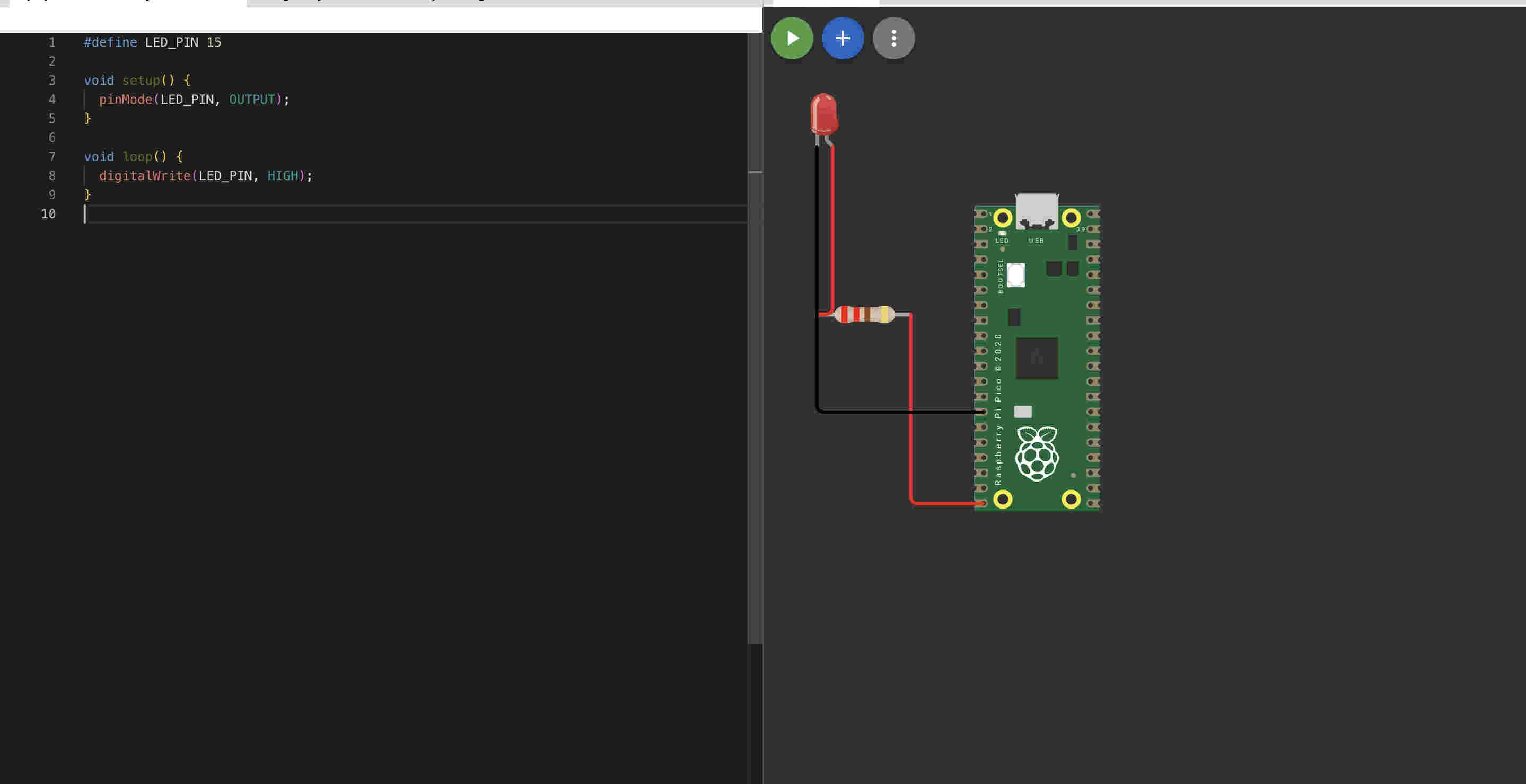
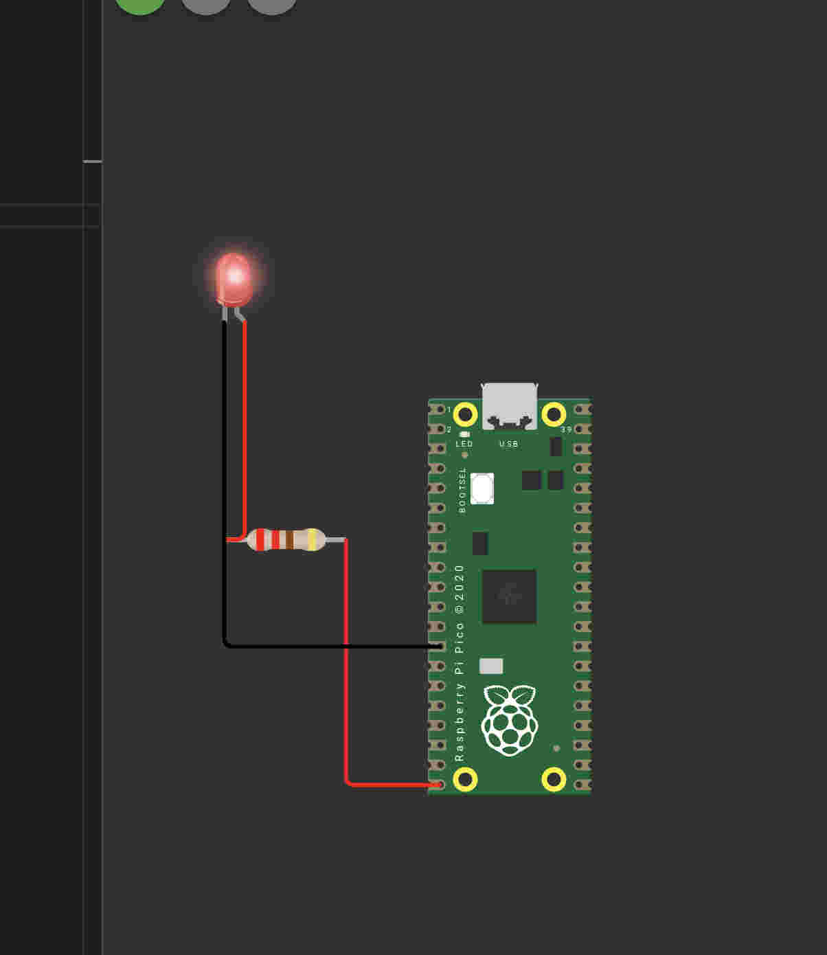
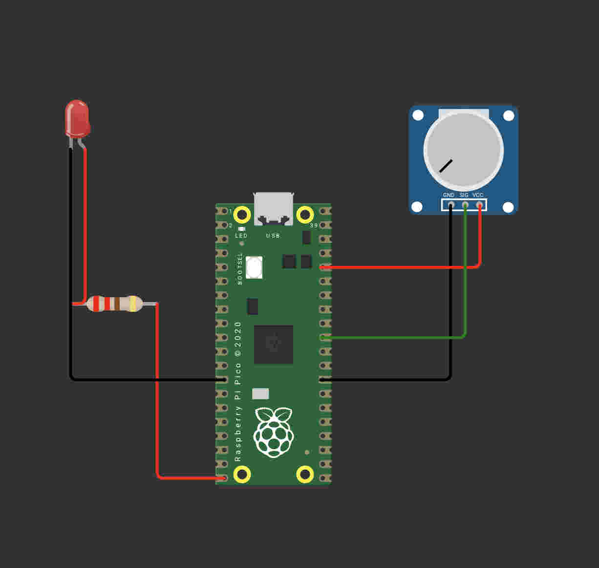
I decided to take ANOTher step down- and decided to use a led with a simple code- to run it AND GAIN SOME CONFIDENCEFINALLY- a resut.Next i decided to add a complication with a potentiometer- Here I mapped the value of the potentiometer to the delay value of the ledAs i increase the value of the potentiometer the blinks slow down
FINALLY WE GET SOMEWHERE
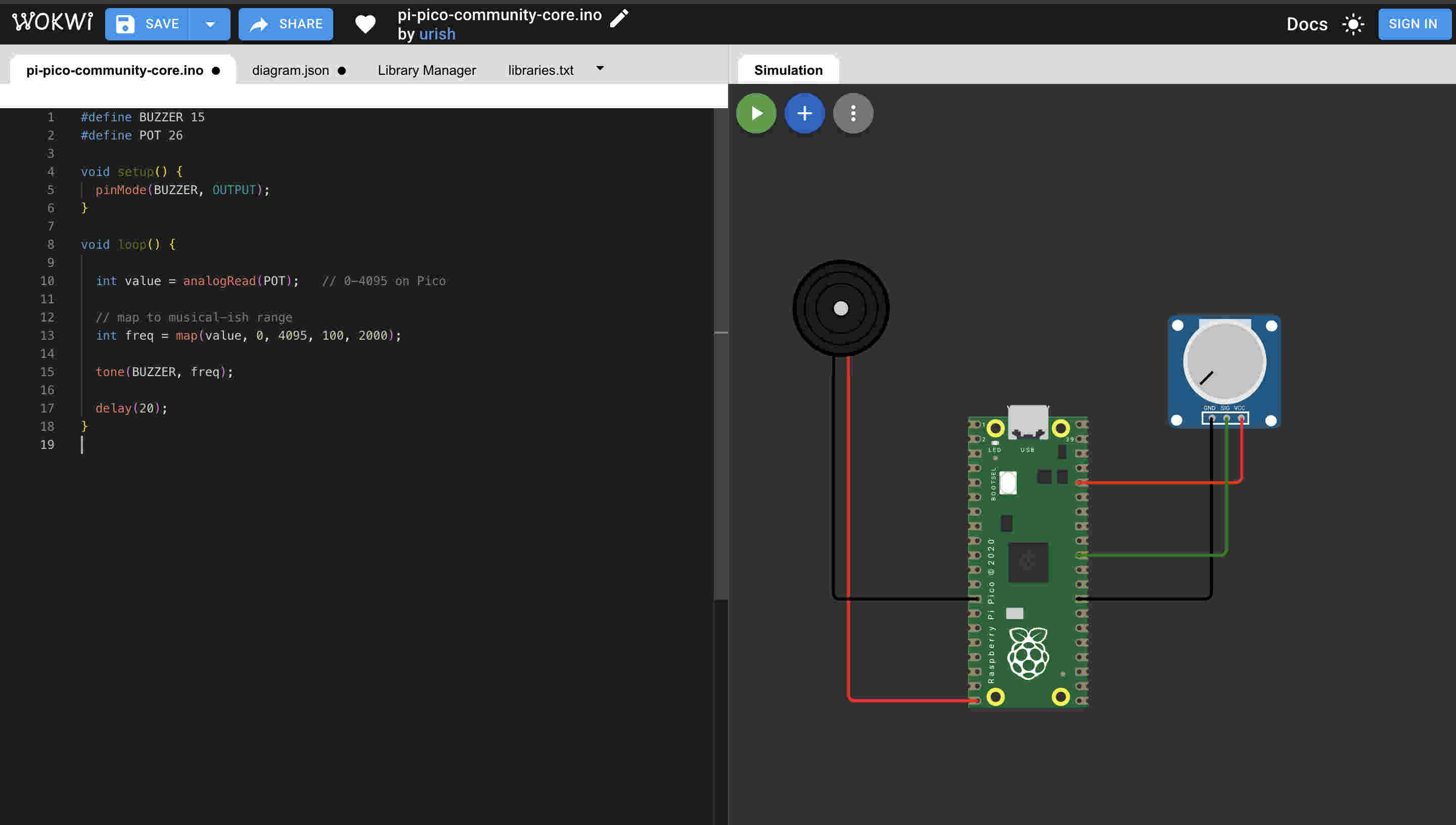
Next i tried soemthing closer to a synth- I used a piezo beeper to get a pitch down pitch up effect. As i increase the value of the potentiometer the pitch gets higher
SUCCESS NUMBER 3---- YES IM COUNTING
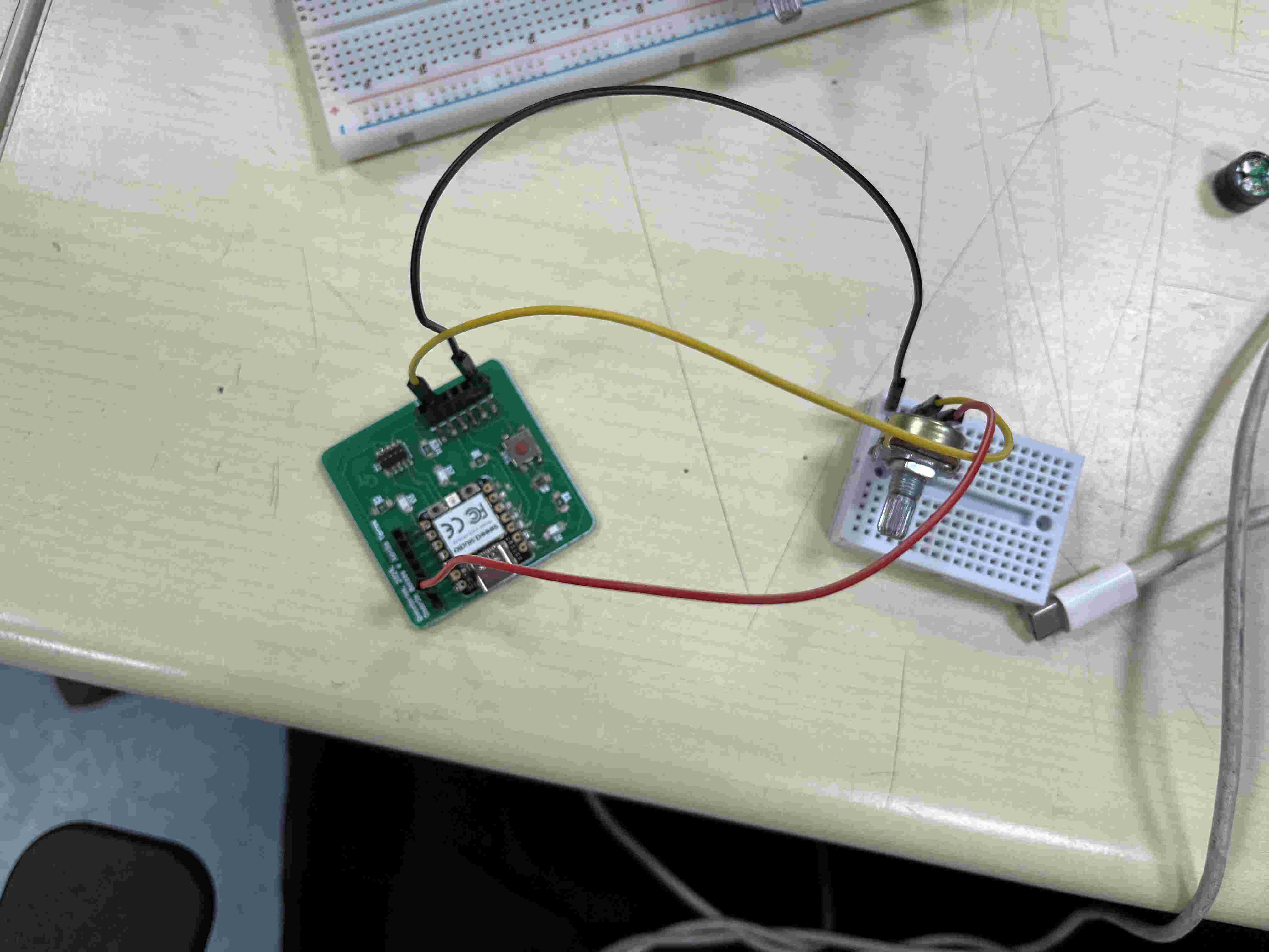
Back to physical with working code
I figured out the wiring pins using the Same array method and wired to analog pin 3 I got correct readings on my serial monitor after connecting succefullyNext i tried output with just codeNo input is being used here