FINAL PRESENTATION

My Final Project process
I really wanna work on something that blends electronics and mechanics
Research
couple of ideas
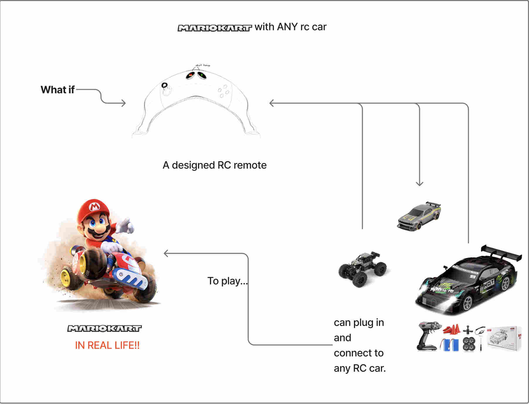
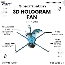
My final Project
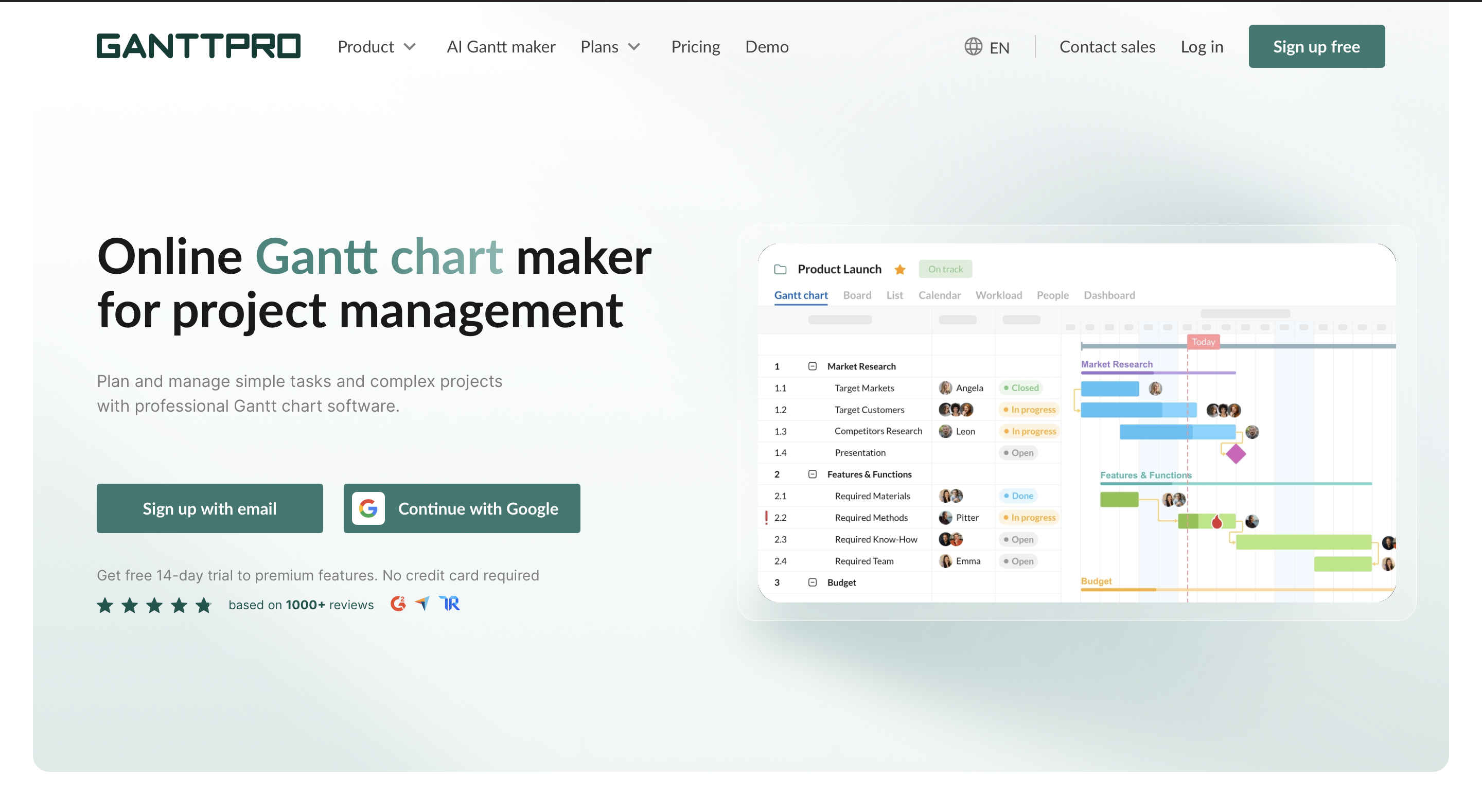
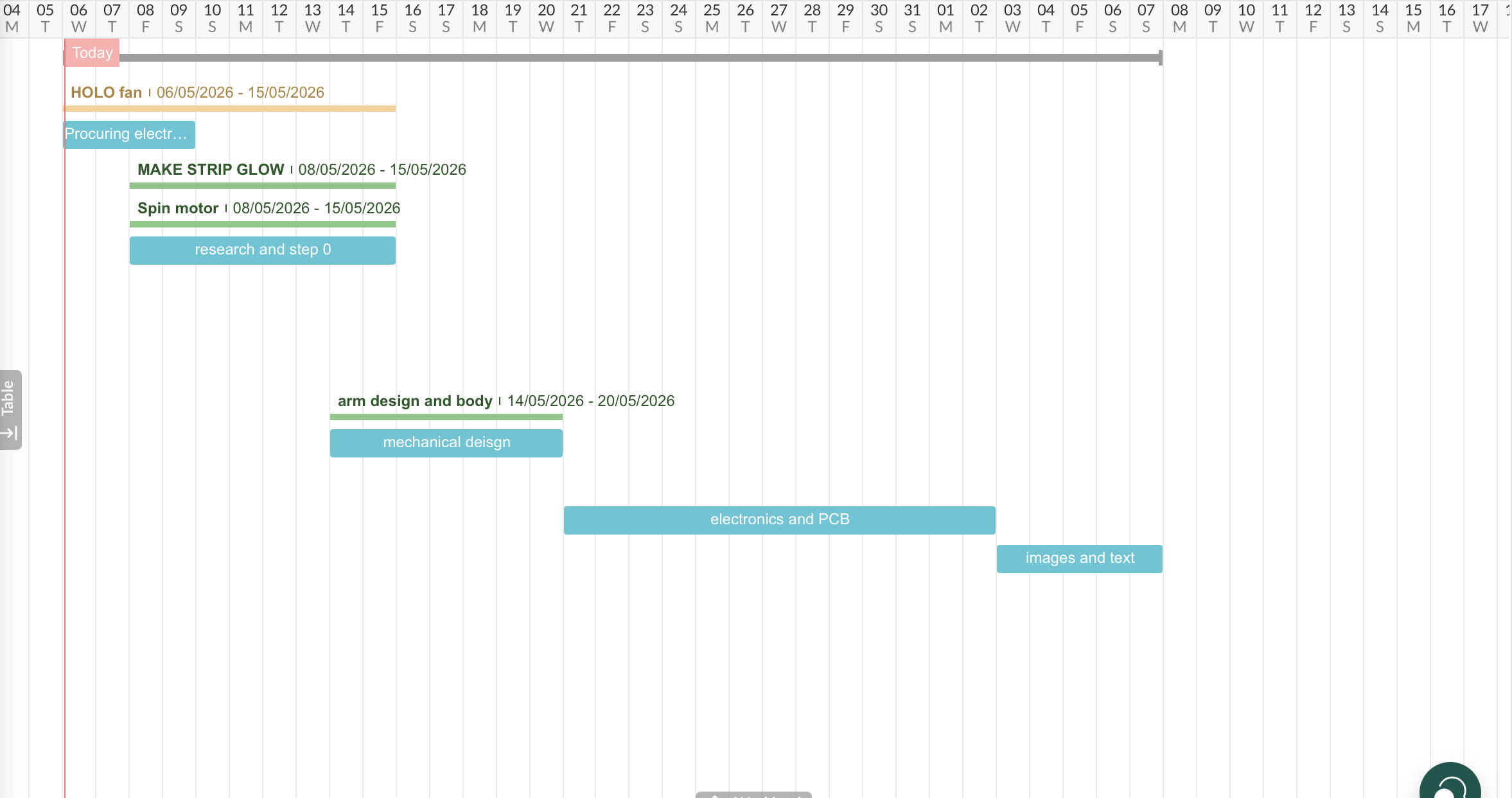
A Gantt chart is a visual project management tool that maps out a project schedule, displaying tasks as horizontal bars against a timeline
You can make your own here
Gantt chart
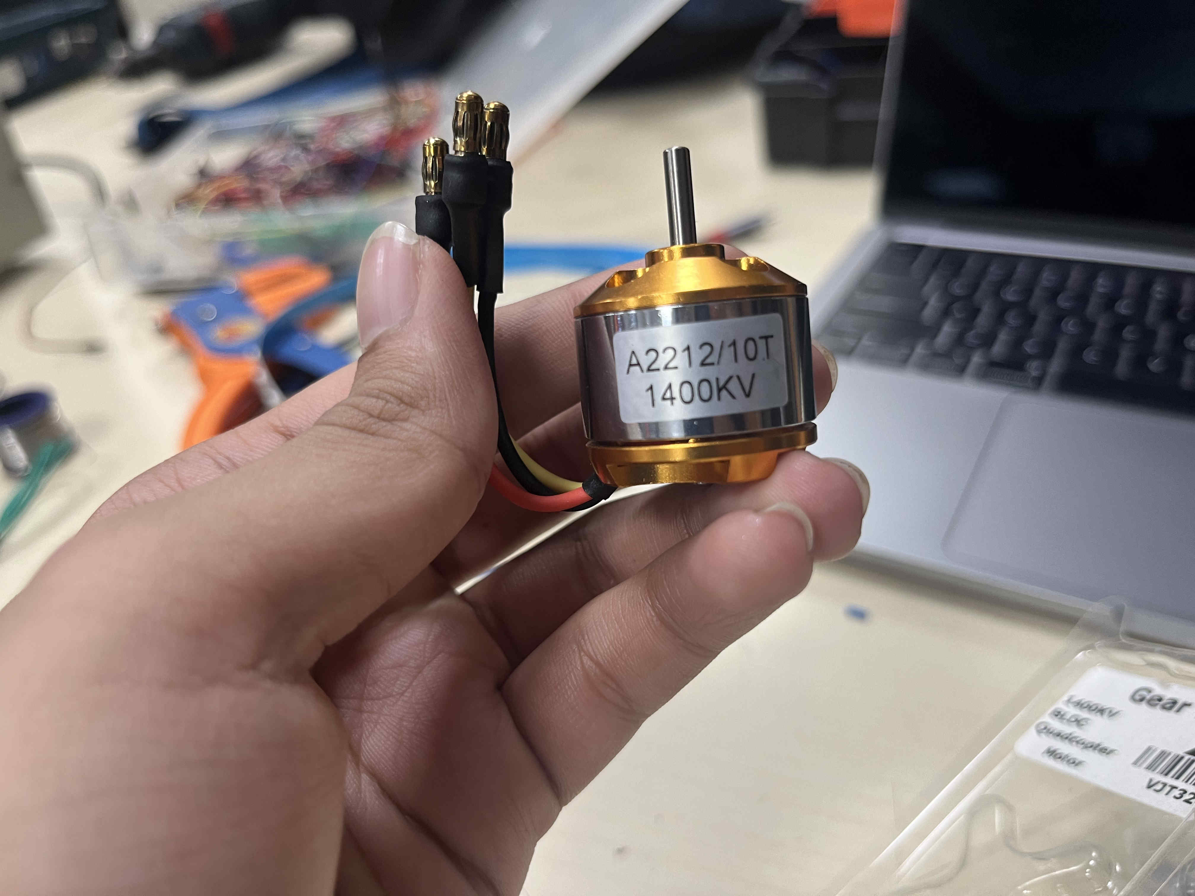
Parts selection
Before we start it is important to understand a few terms
POV
Simple intuition If you wave a glowing stick fast in the dark: You don’t see a dot You see a continuous light trail That “trail” isn’t real — it’s your brain stitching moments together.

and are not consistent

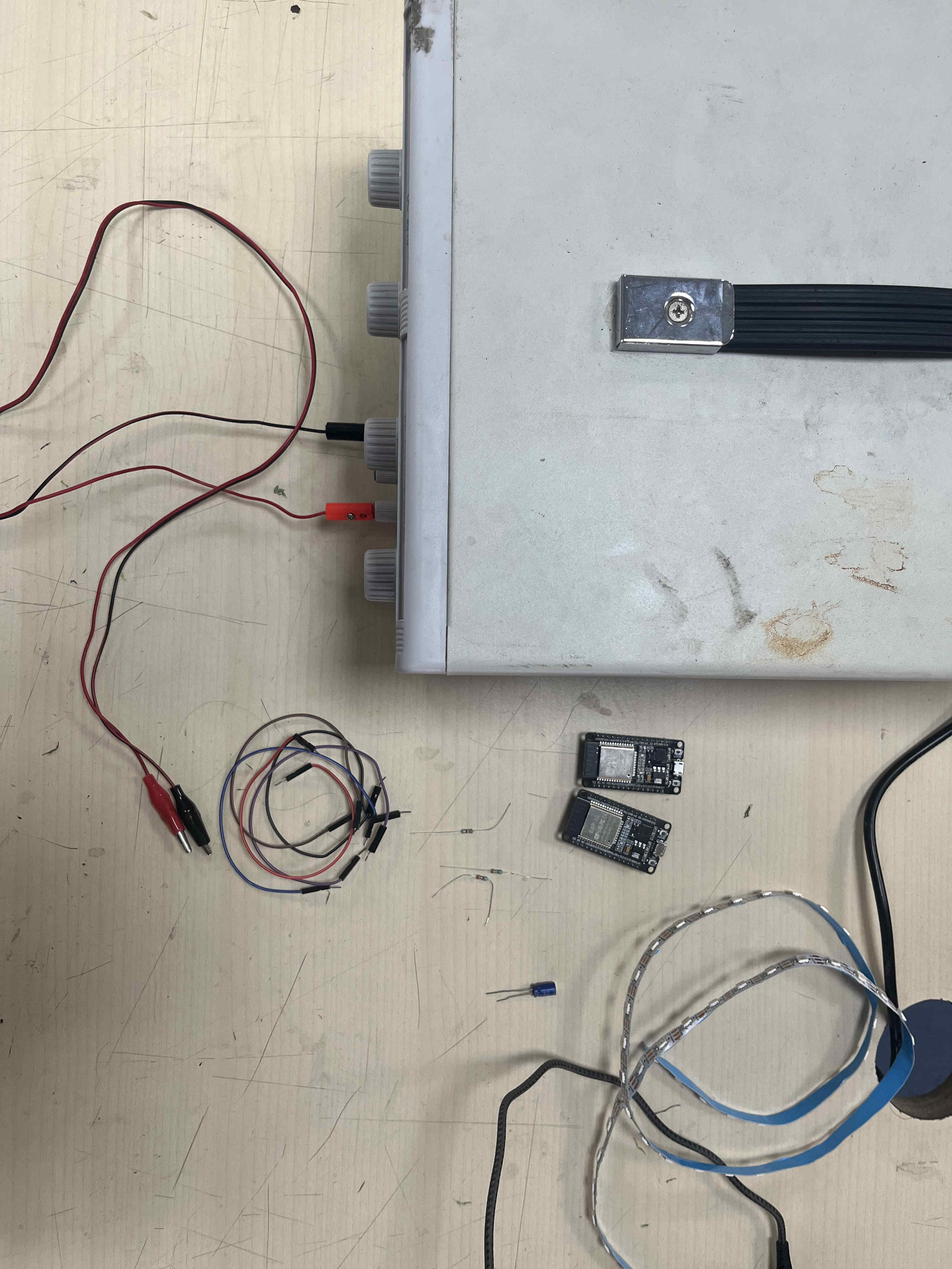
& a esp32 devkit for prototyping
once i move to interaction i will also be using a esp 32 sense board for the camera.

Designs
Here is the basic plan for the design
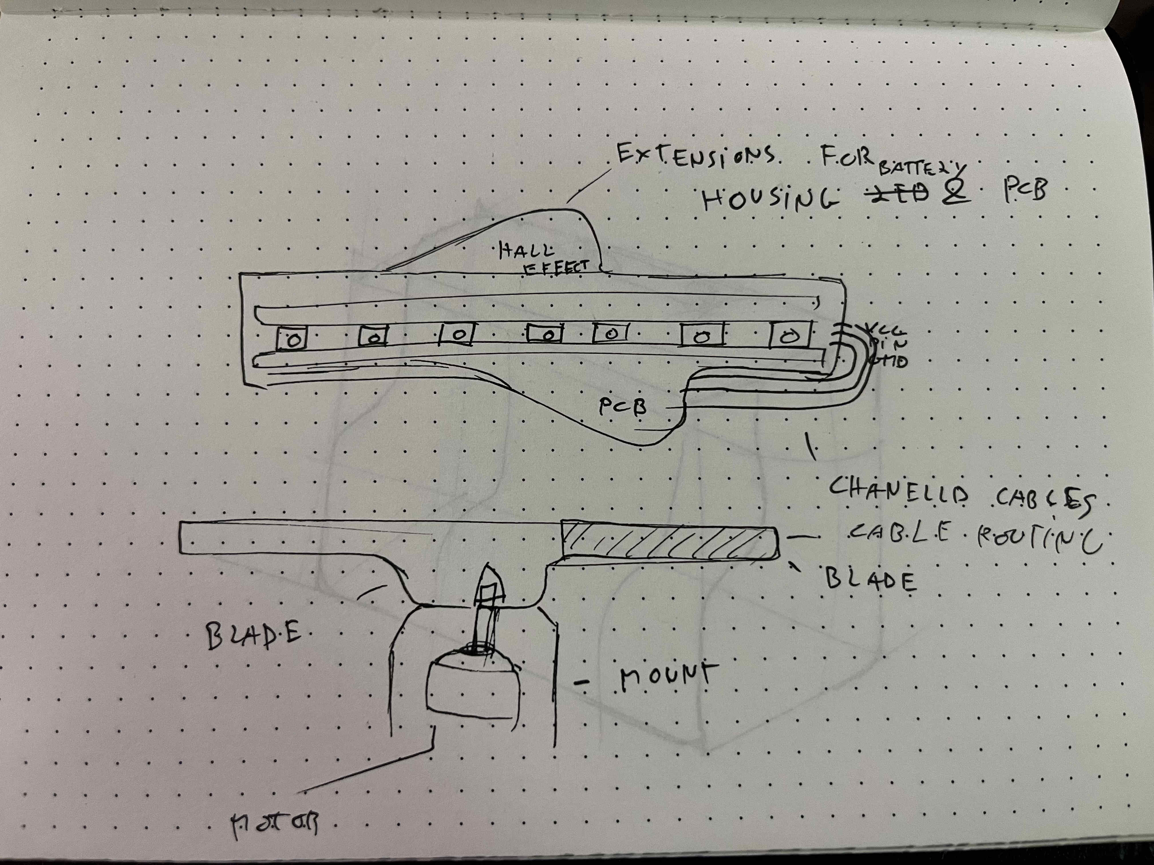
This is the design for the blade,
Idea is to have a repairable inner sleeve fro neopixels and a fixed blade to the motor.
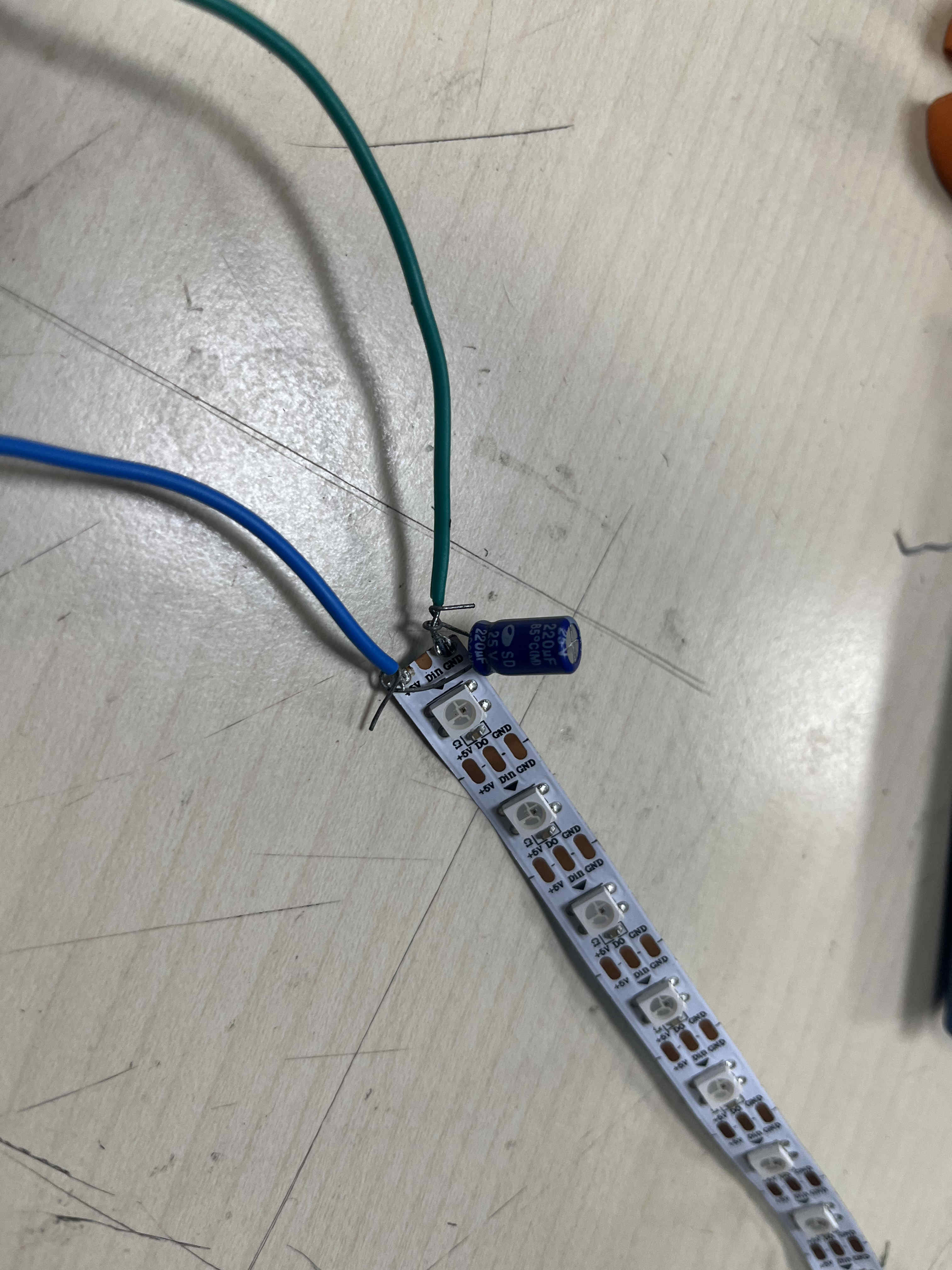
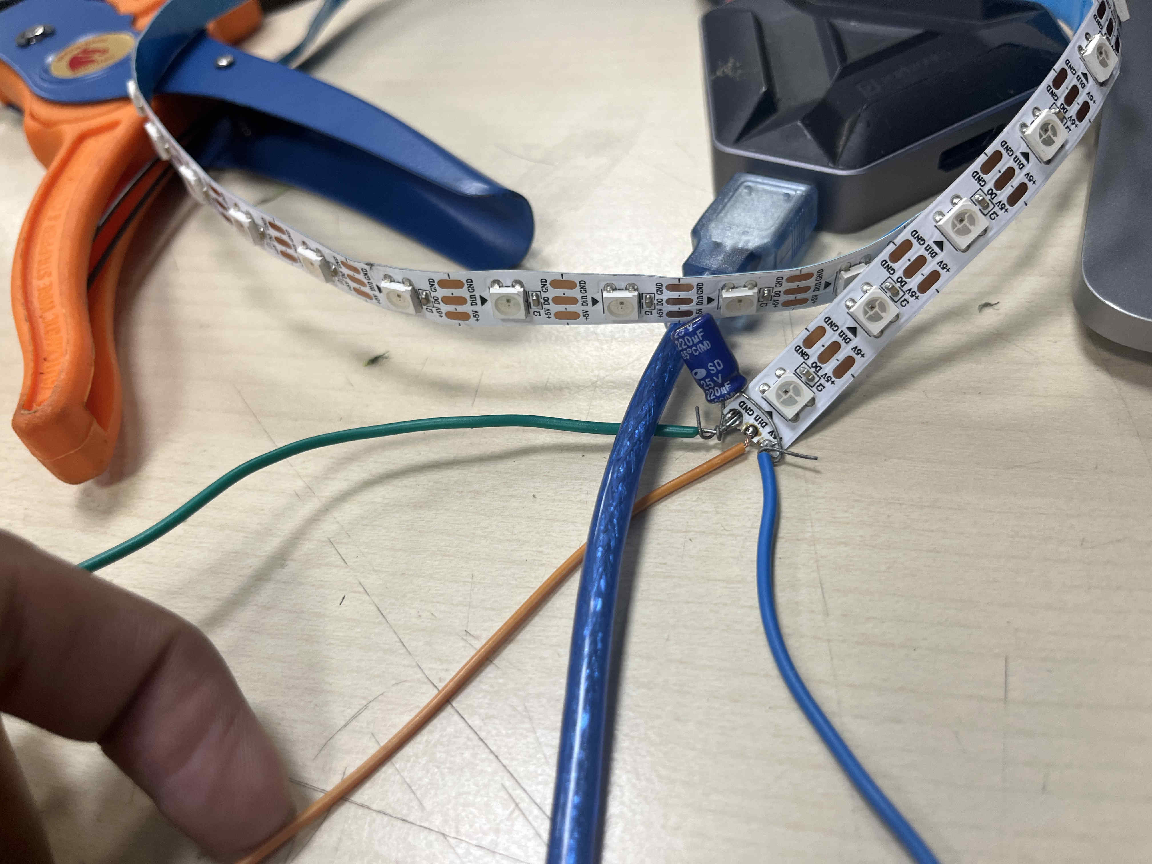
Trial Neopixel blinks
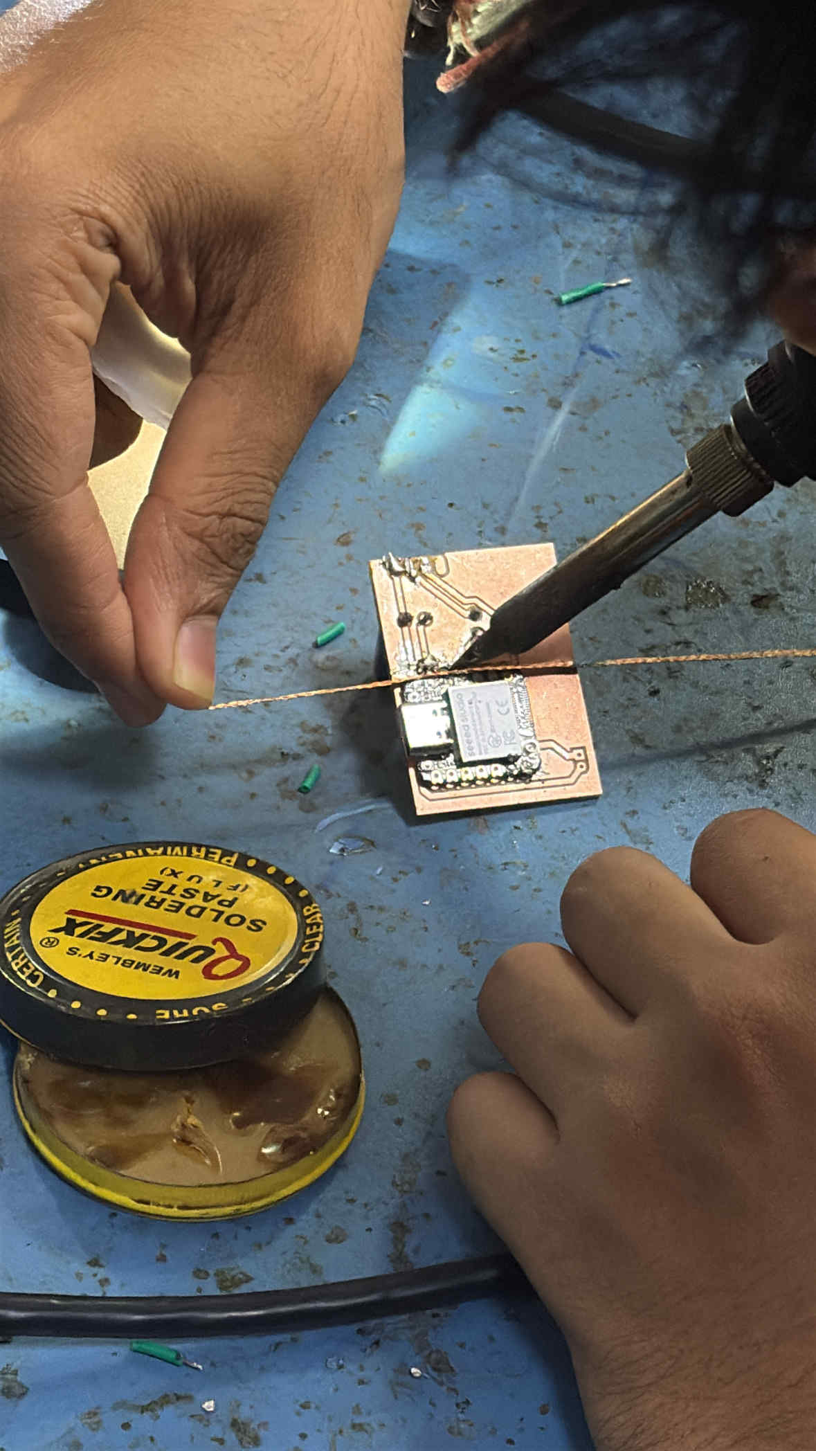
I start by getting control of each led.
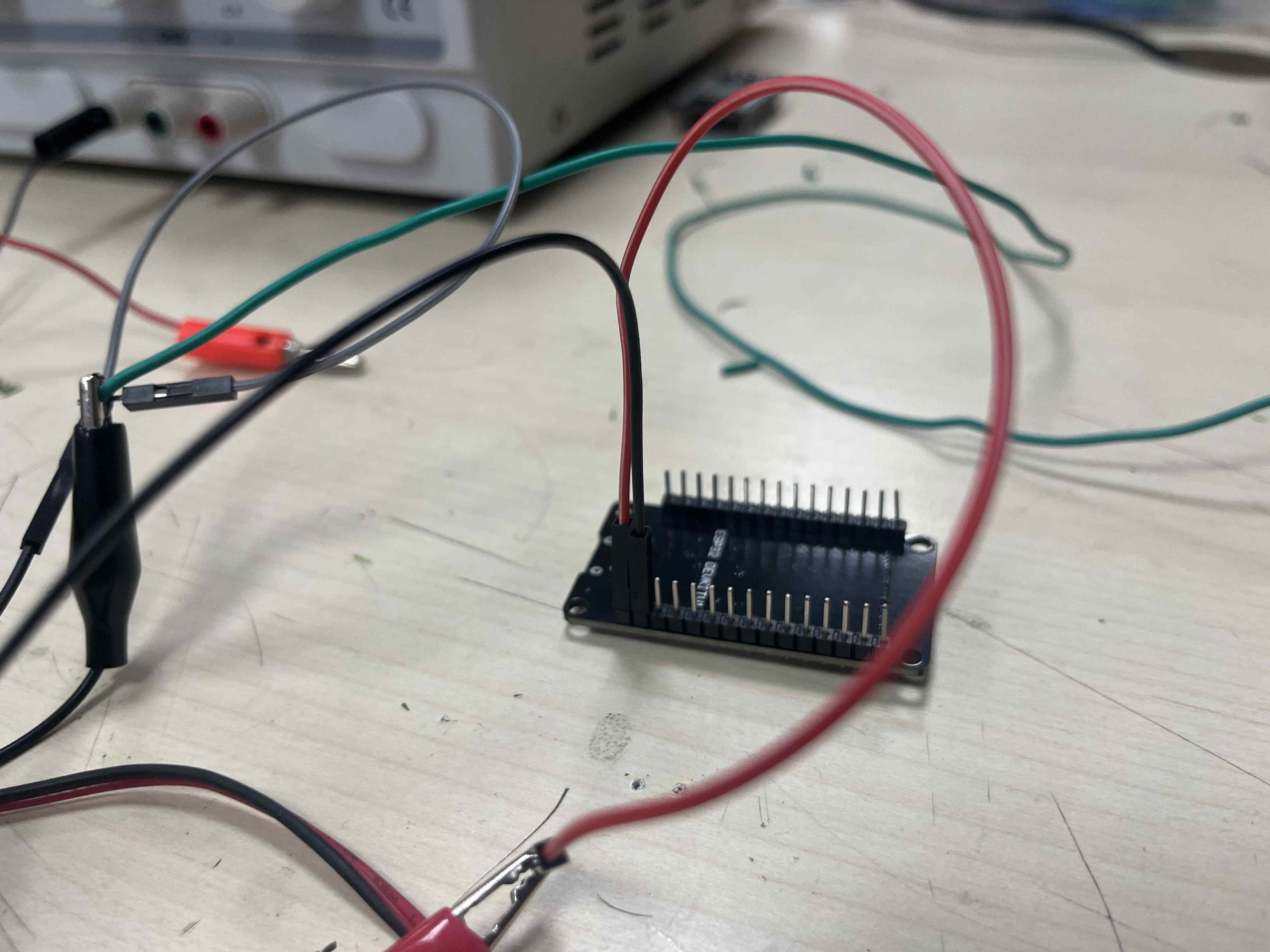

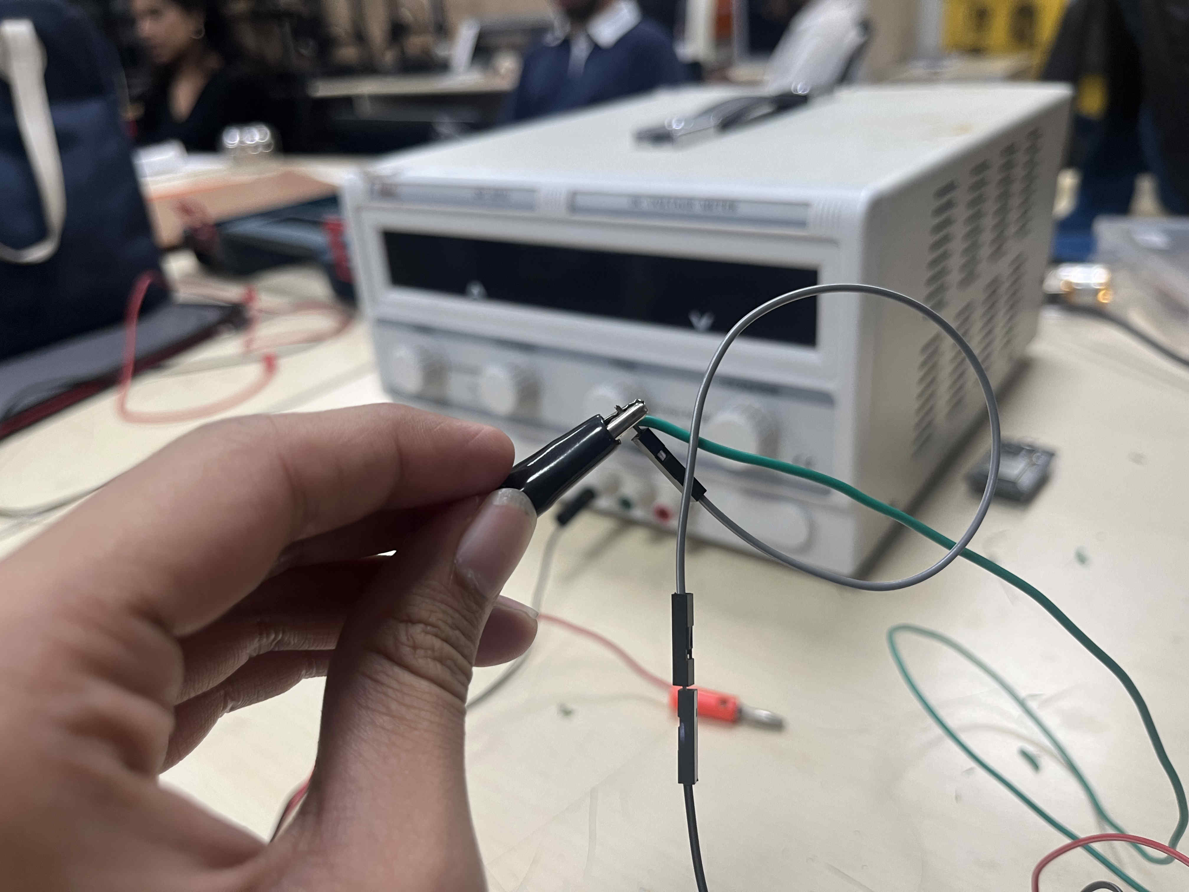
Be careful on keeping wires away from eah other
  #include Adafruit_NeoPixel.h>

#define PIN 4
#define NUM_PIXELS 30

Adafruit_NeoPixel strip(NUM_PIXELS, PIN, NEO_GRB + NEO_KHZ800);

void setup() {
  strip.begin();
  strip.show();
}

void loop() {
  for(int i = 0; i < NUM_PIXELS; i++) {
    strip.setPixelColor(i, strip.Color(255, 0, 0));
  }
  strip.show();
  delay(500);
}
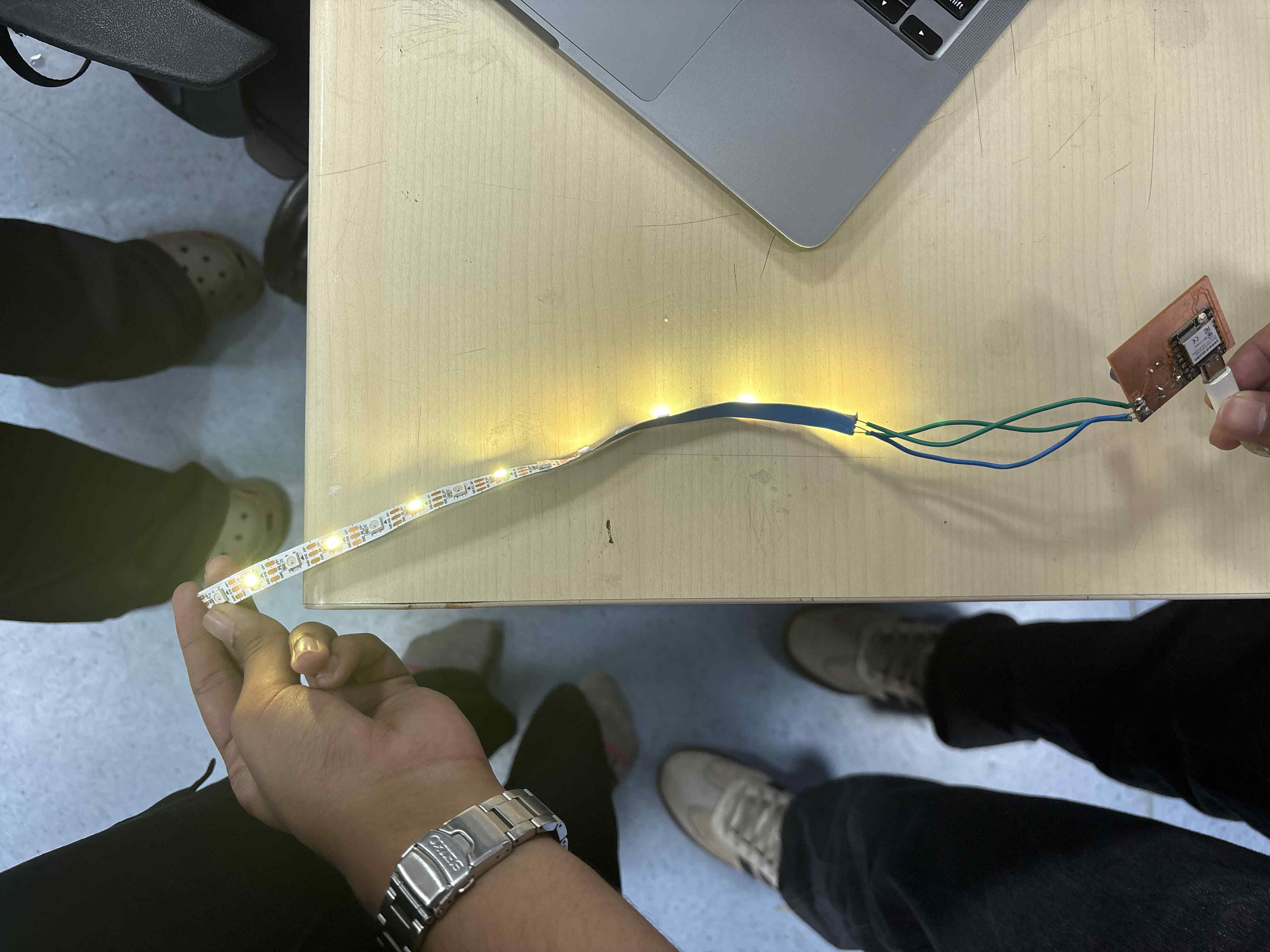
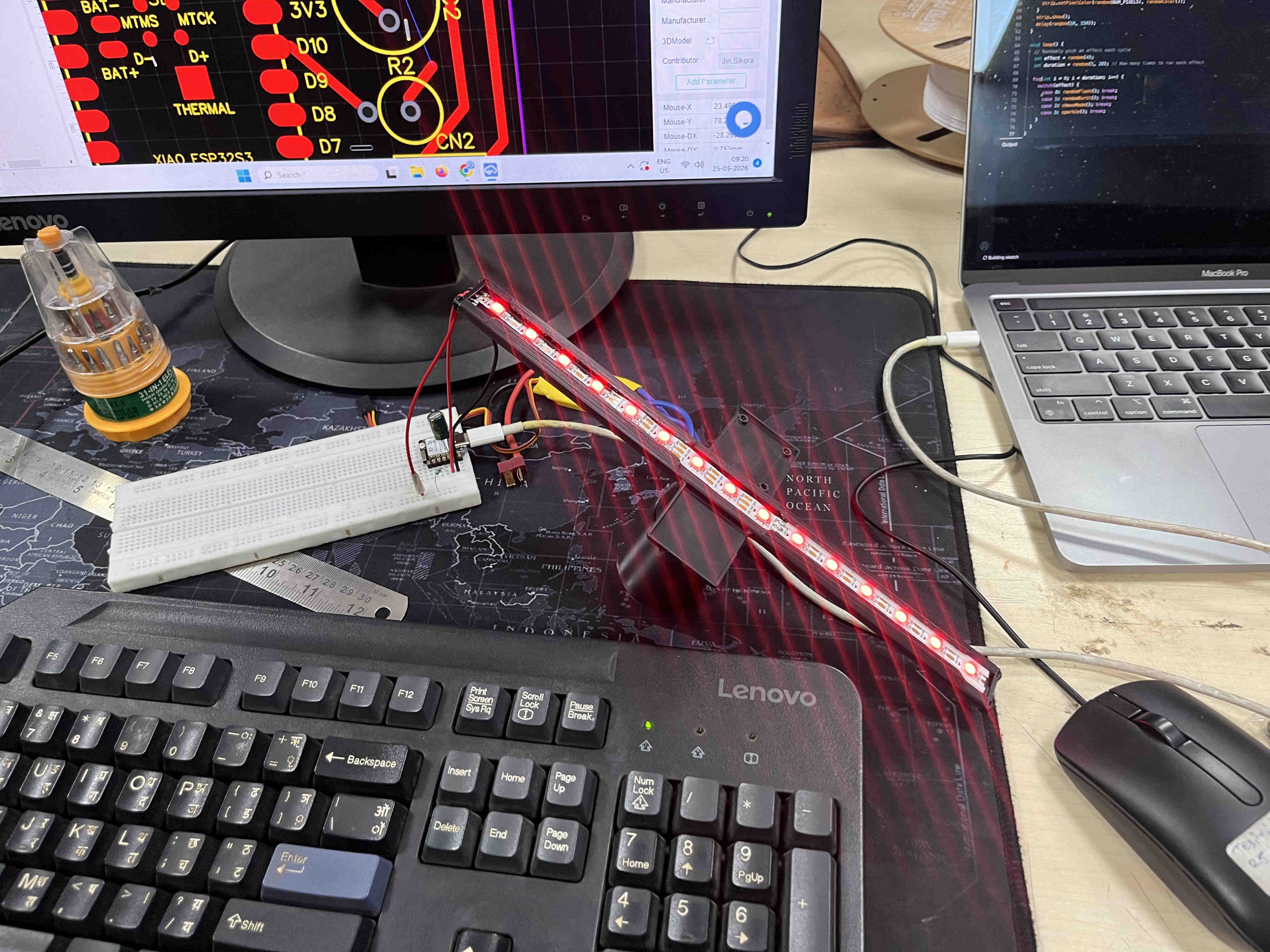
Above is a test code for glowing red
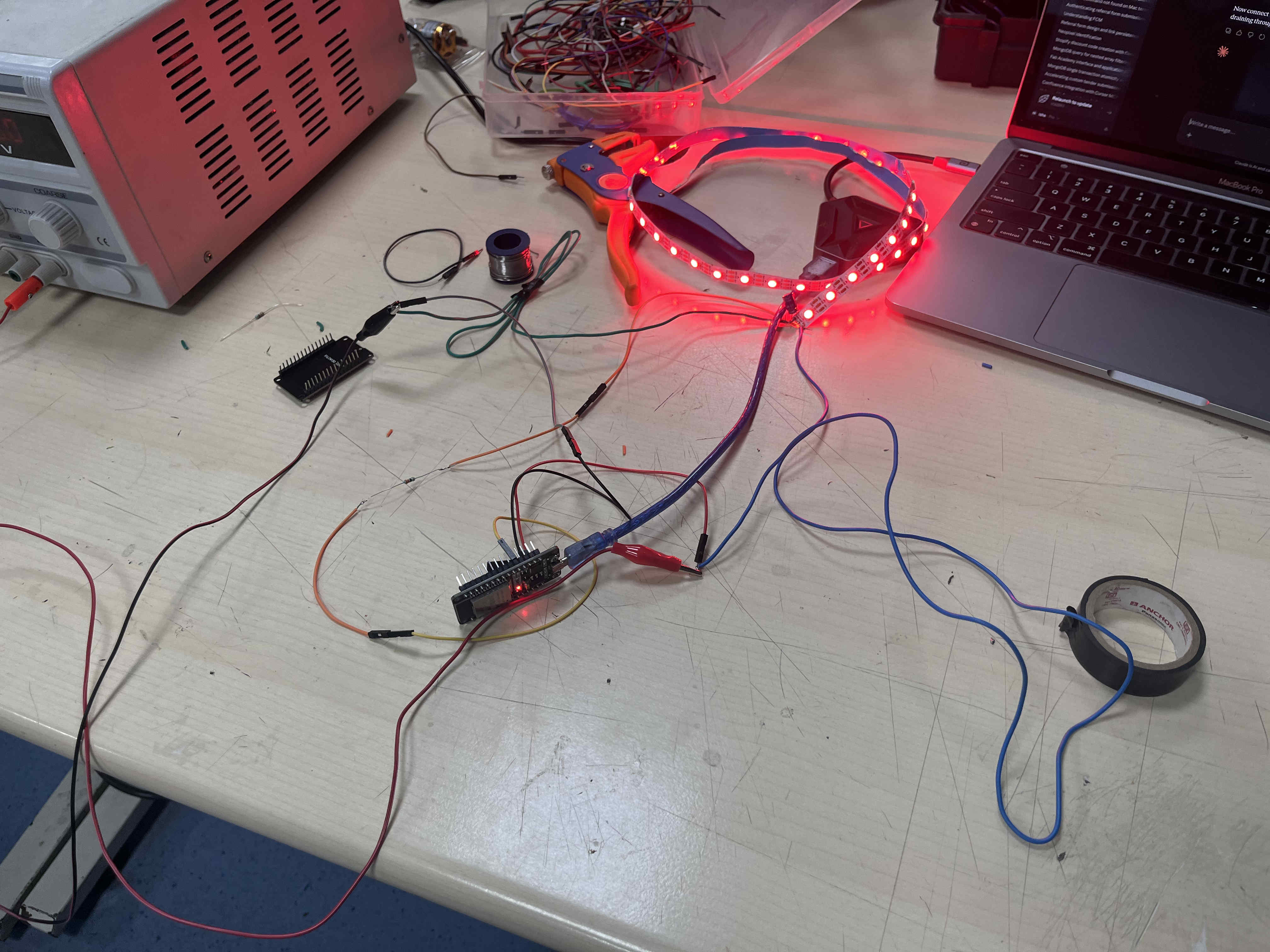
Result
  #include

#define PIN 4
#define NUM_PIXELS 56

Adafruit_NeoPixel strip(NUM_PIXELS, PIN, NEO_GRB + NEO_KHZ800);

void setup() {
  strip.begin();
  strip.show();
}

void colorWipe(uint32_t color, int wait) {
  for(int i = 0; i < strip.numPixels(); i++) {
    strip.setPixelColor(i, color);
    strip.show();
    delay(wait);
  }
}

void loop() {
  colorWipe(strip.Color(255, 0, 0), 50); // Red
  colorWipe(strip.Color(0, 255, 0), 50); // Green
  colorWipe(strip.Color(0, 0, 255), 50); // Blue
}
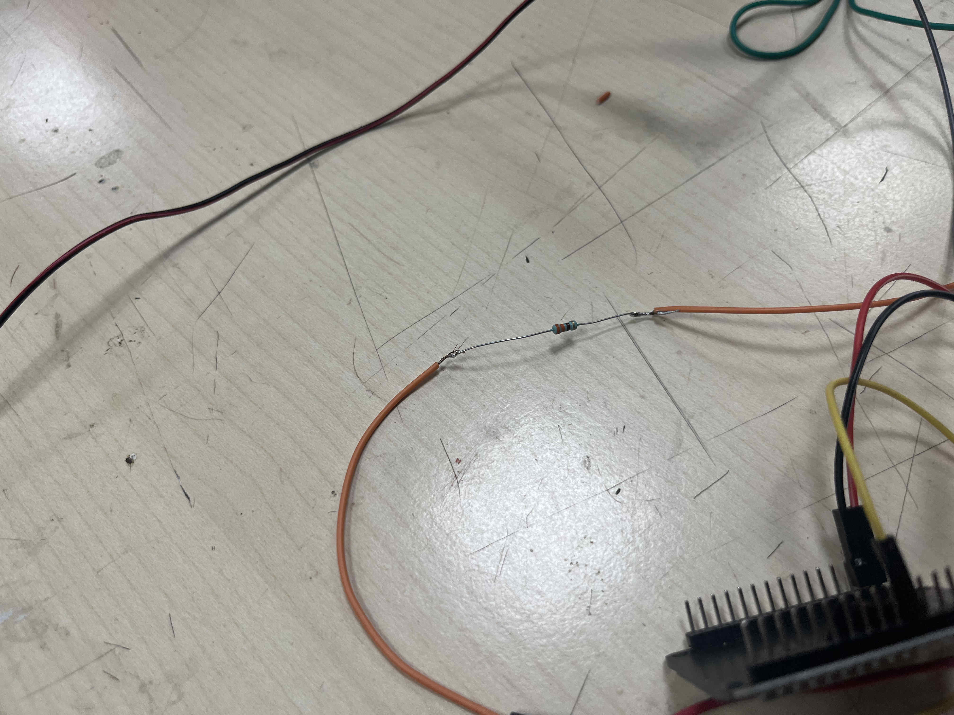
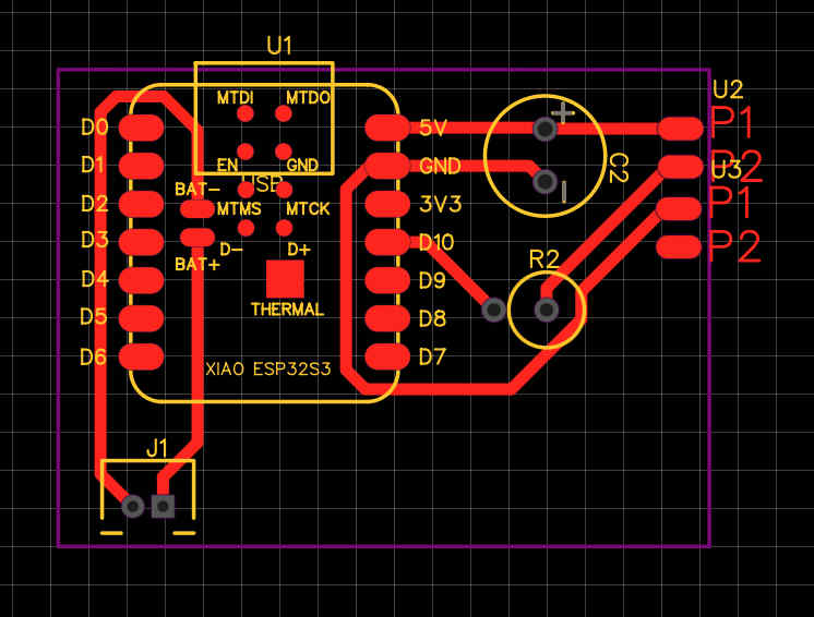
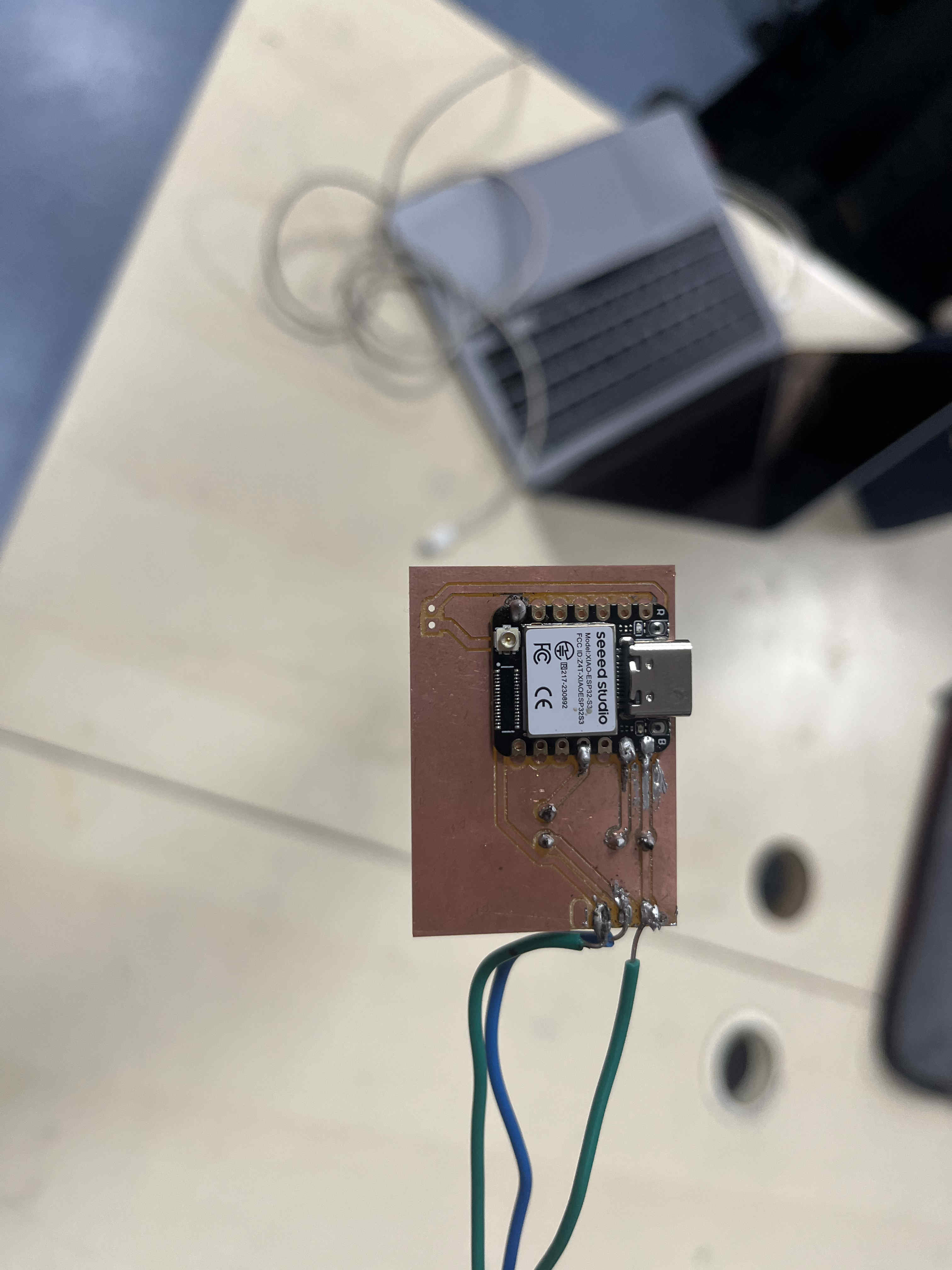
PCB trial Design
For a basic trial design, i started by creating a basic pcb to find out the effect of spinningcomponents at high speed
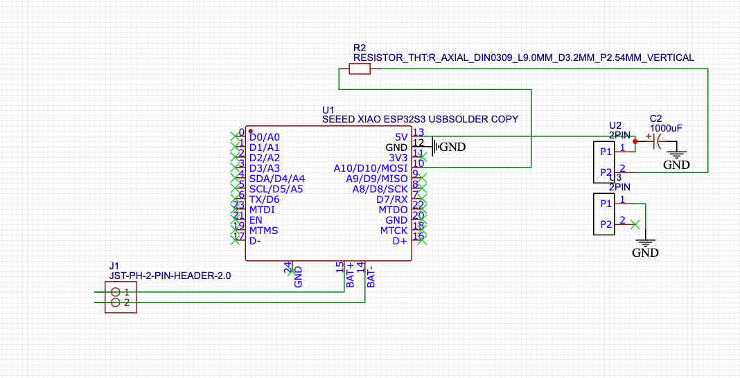
This is the schematic you can refer to
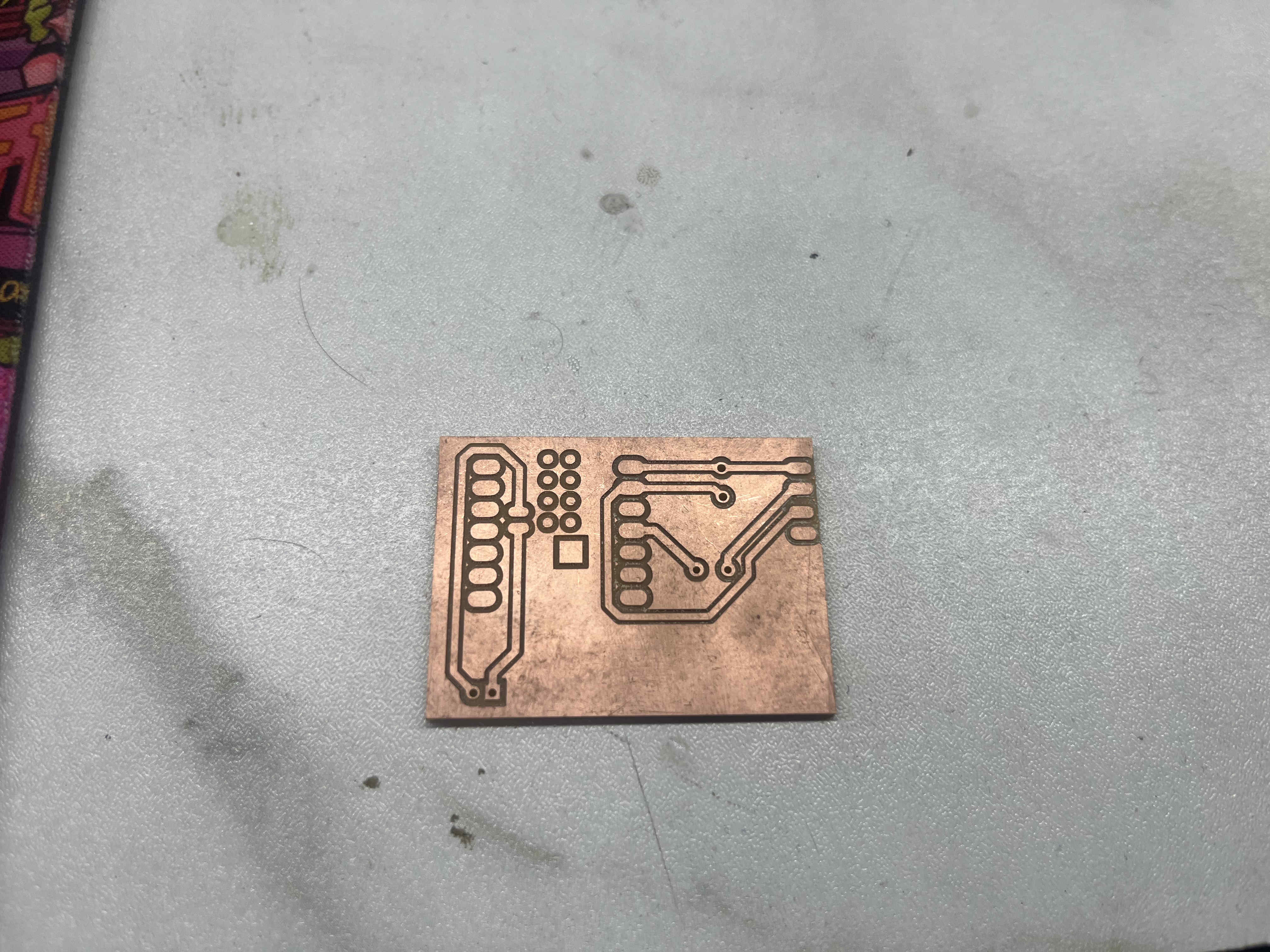
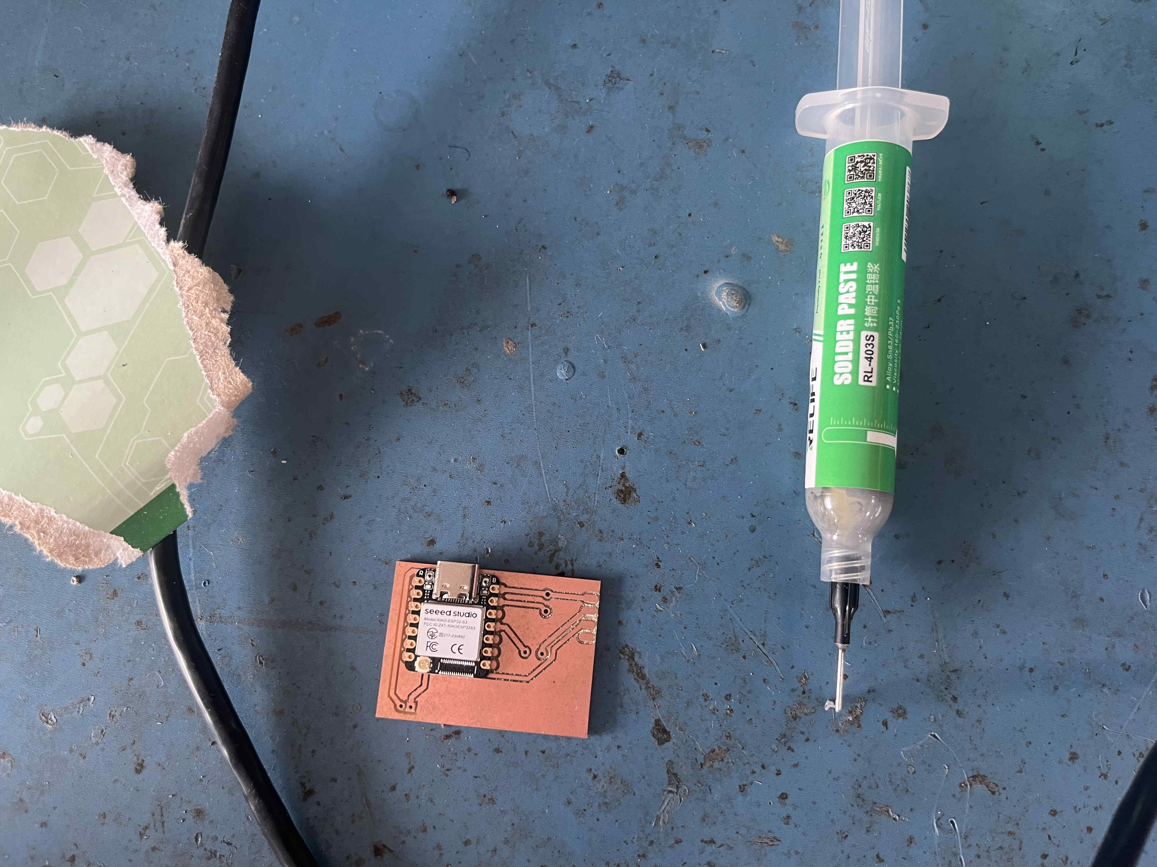

.Proto 1.
Learnings from prototype 1
Prototype 2- final Iteration
after the learnings from proto 1 i moved onto proto 2.
here my utmost importance was the balancing and system integrtion of the blade.
The plan
Improved multipart print.
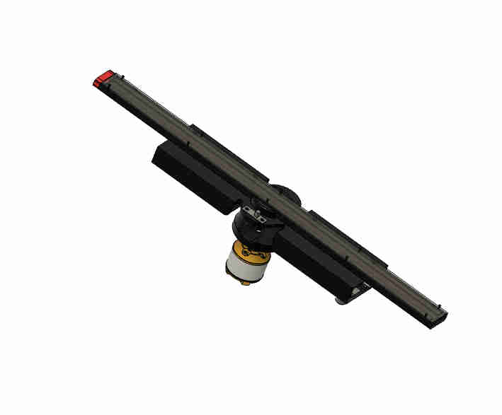
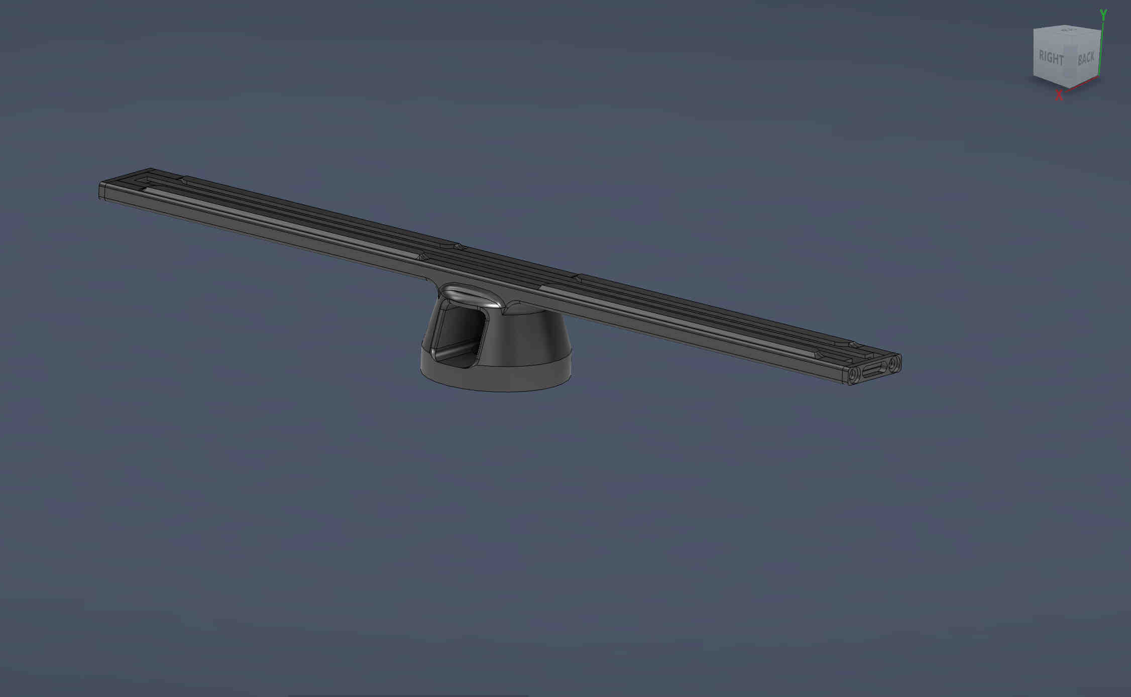
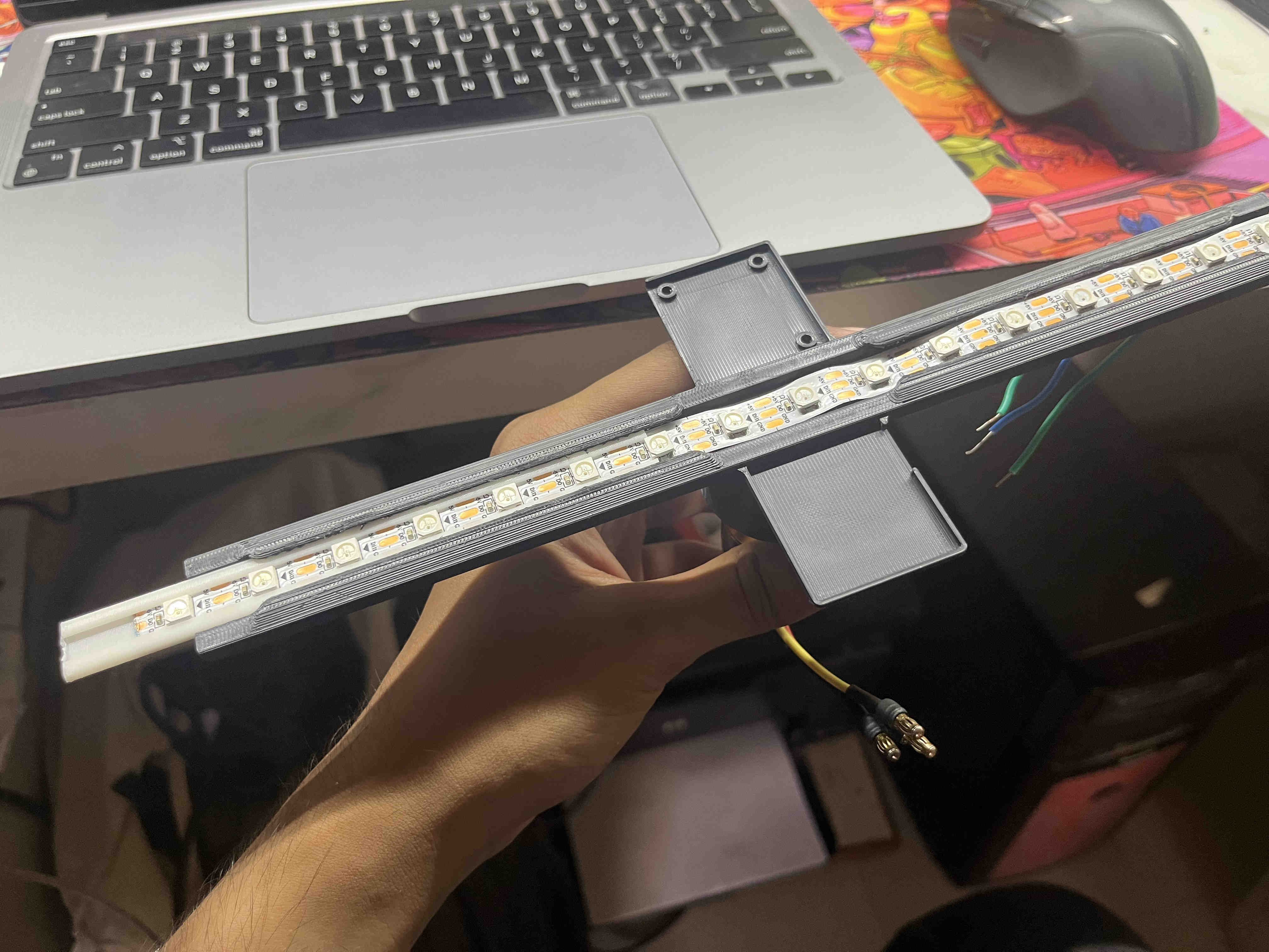
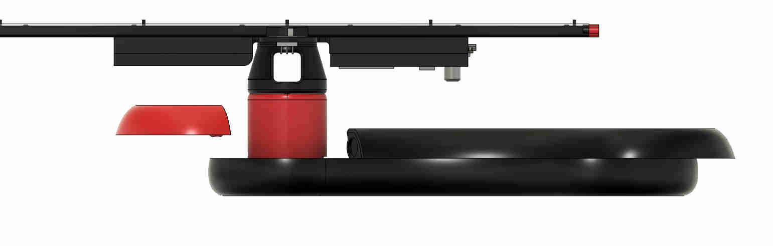
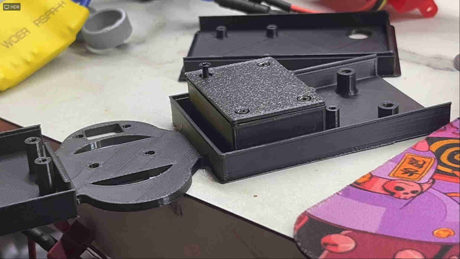
This is how my blade looks like assembled
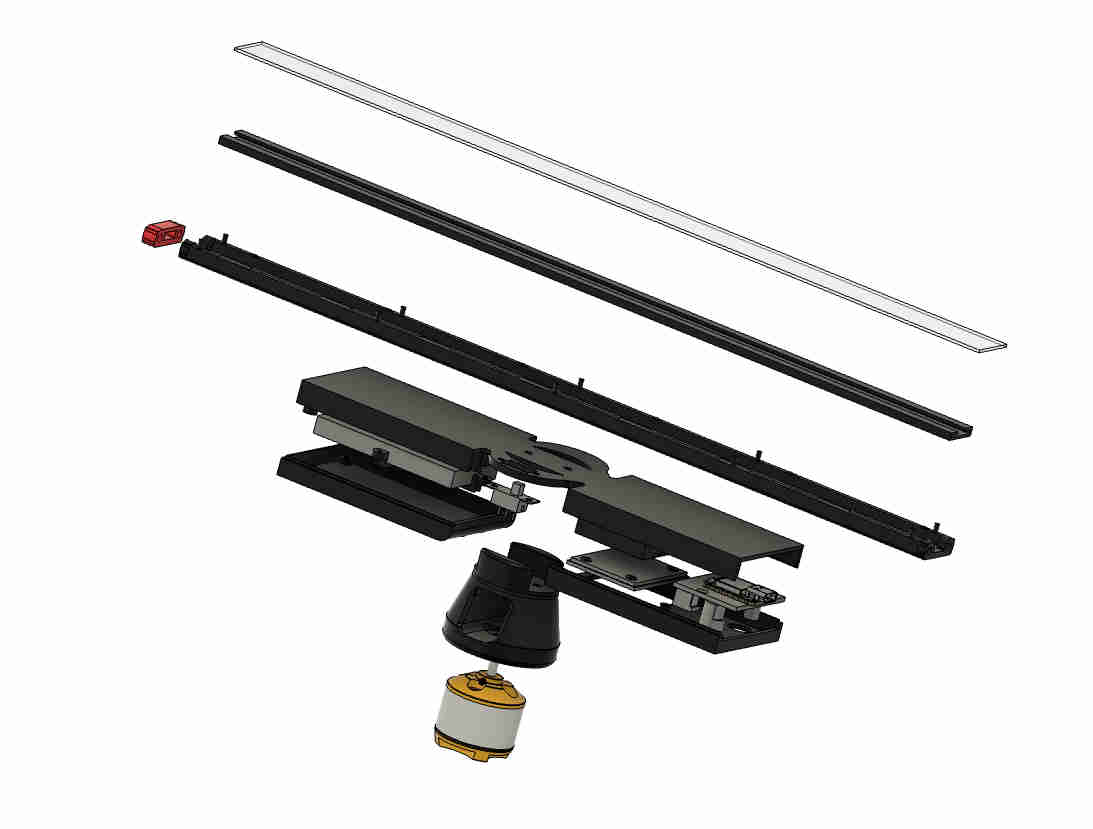
These are the mutiple parts i have diveded the same blade in
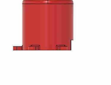
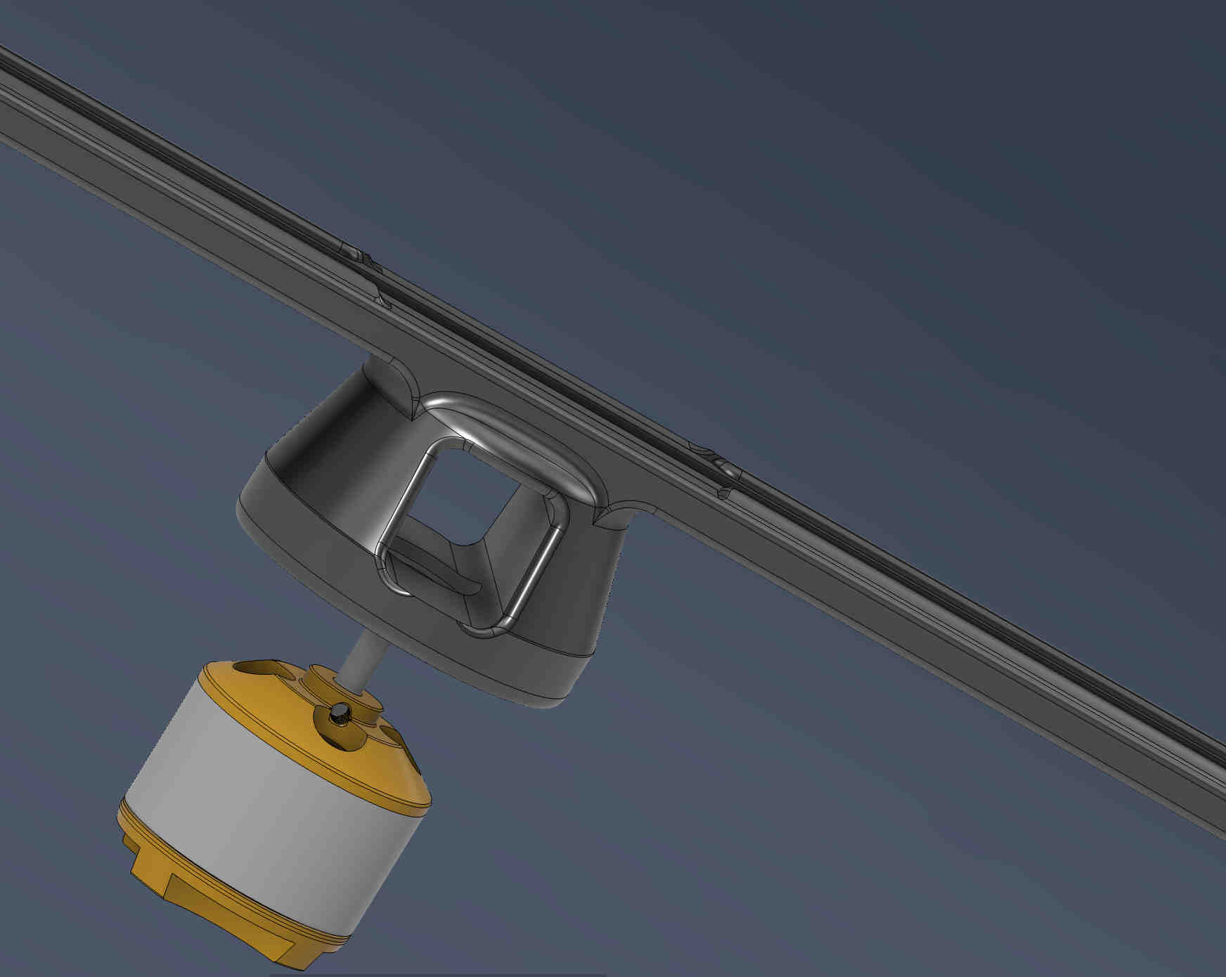
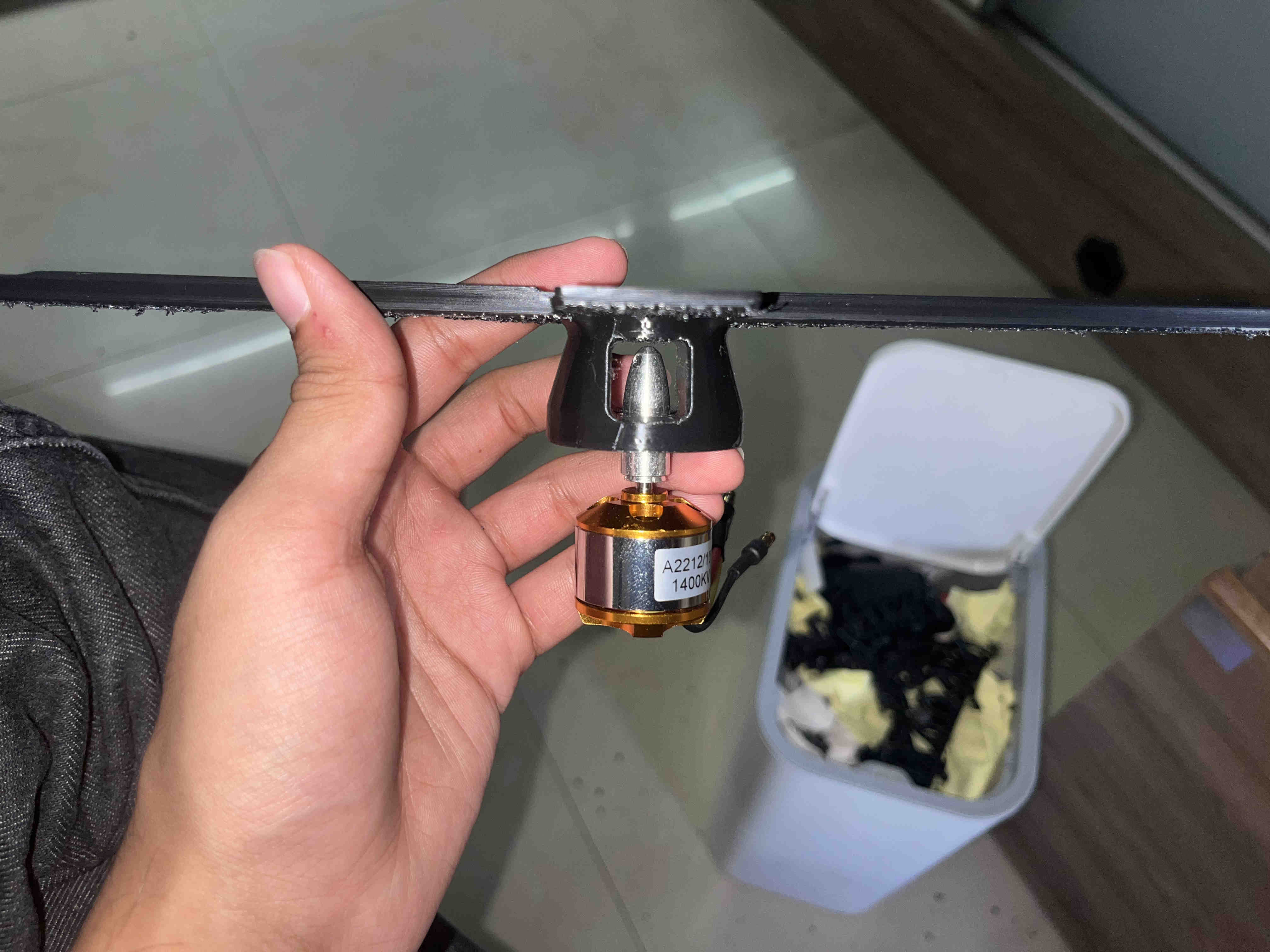
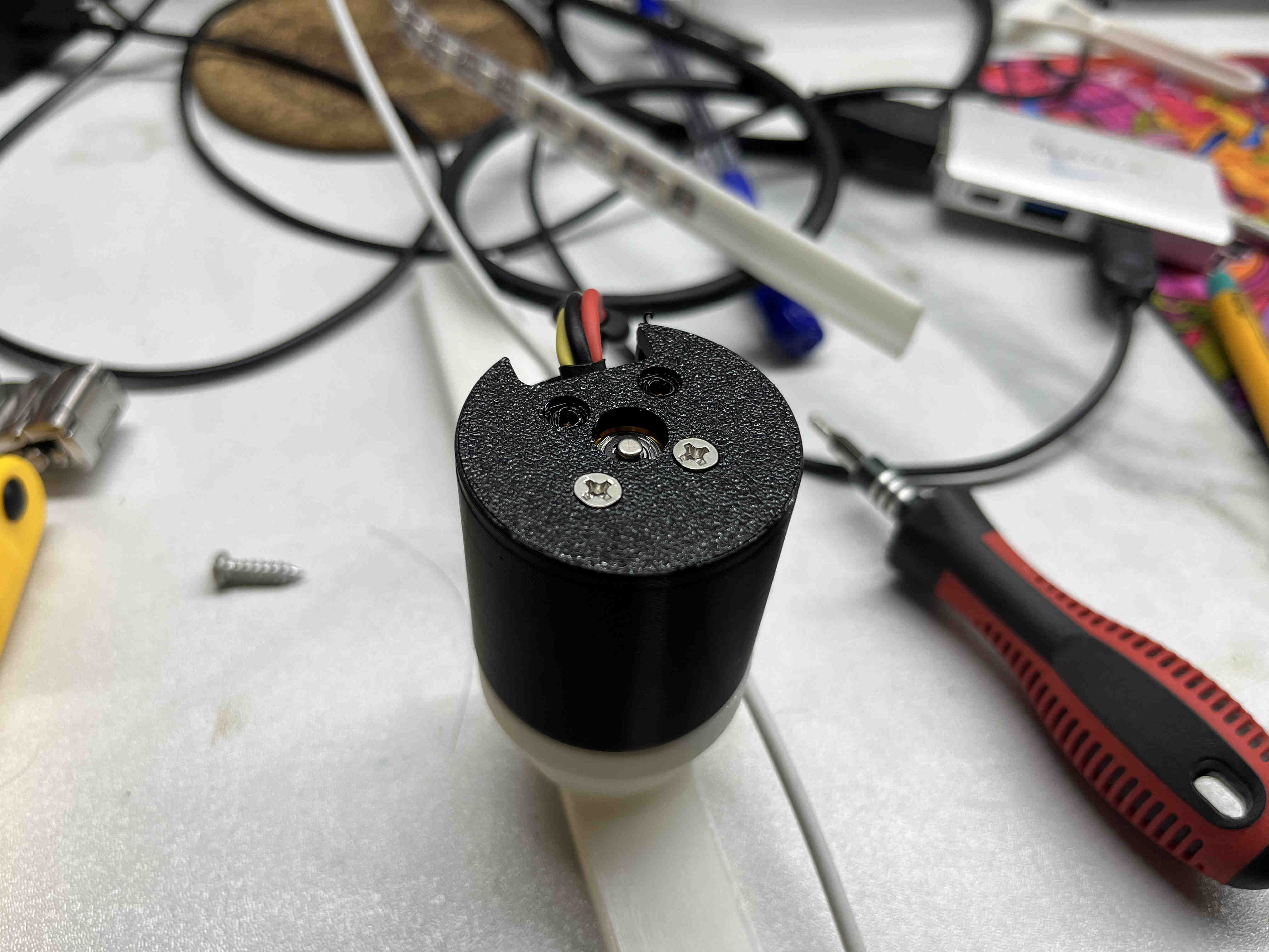
This is the housing for the drone motor.
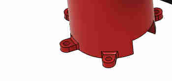
It had holes for m3 bolts to firmly hold itself to the base.
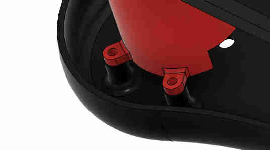
The base had corresponding holes with threaded inserts for holfing the motor housing.
All srew holes outside the body were designed with finish in mind, with steps so that the screws and bolts stay flush.
The top half the base also was designed in two parts with a magnetic snap to provide easy assembly of the blade system to the base system
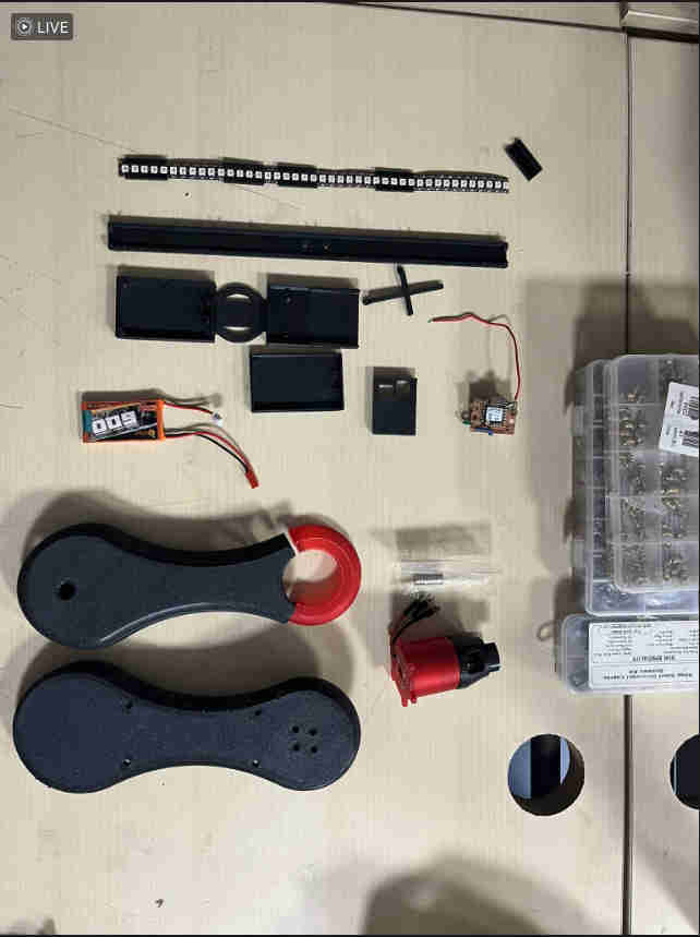
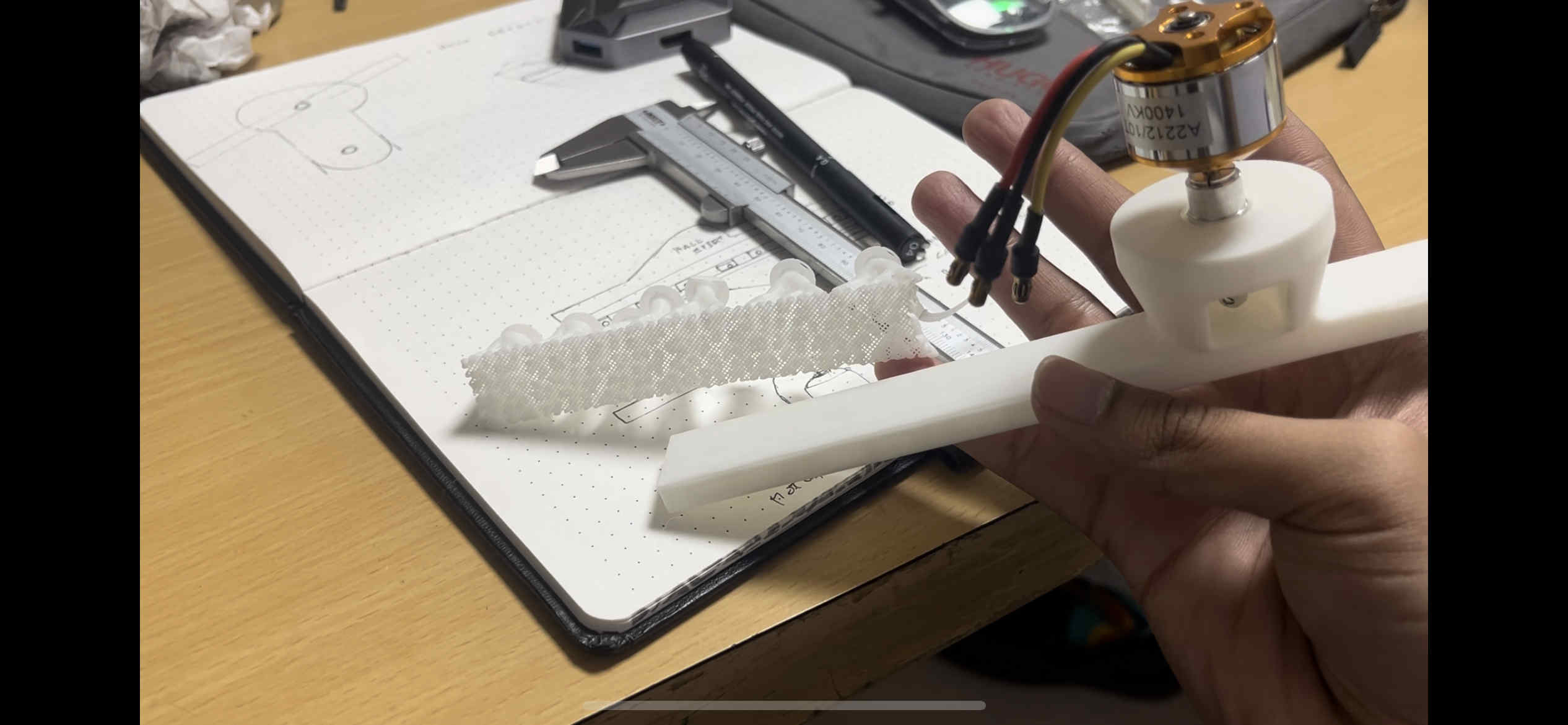
ALl components laid out
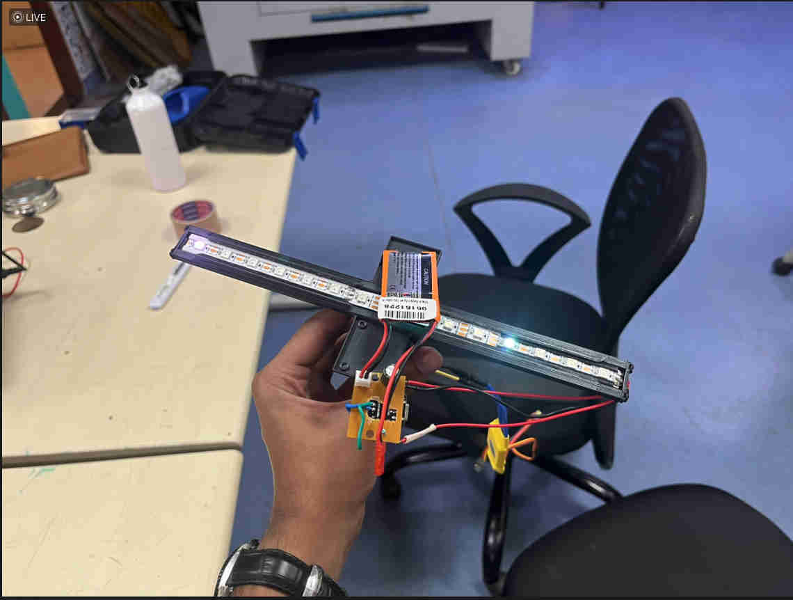
This was the first prototype. so the jump to the newer design was amazing.
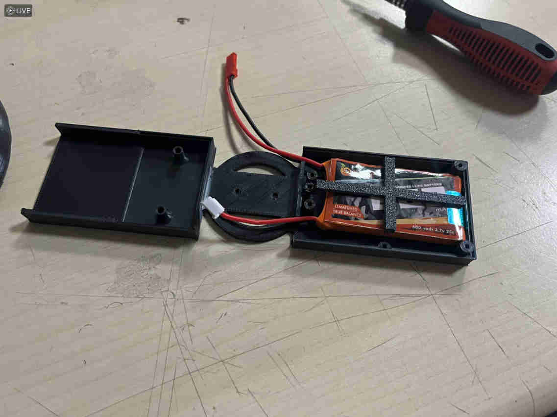
The battery gets bolted on as such. with a custom printed holder.
the blade was fully assembled but extremelyyyyy unstable. main reason being one side of the blade held the heavy 3.7v battery and the other was mostly empty with a light pcb and wires
i started thinking of ways to improve stability in the current form itself
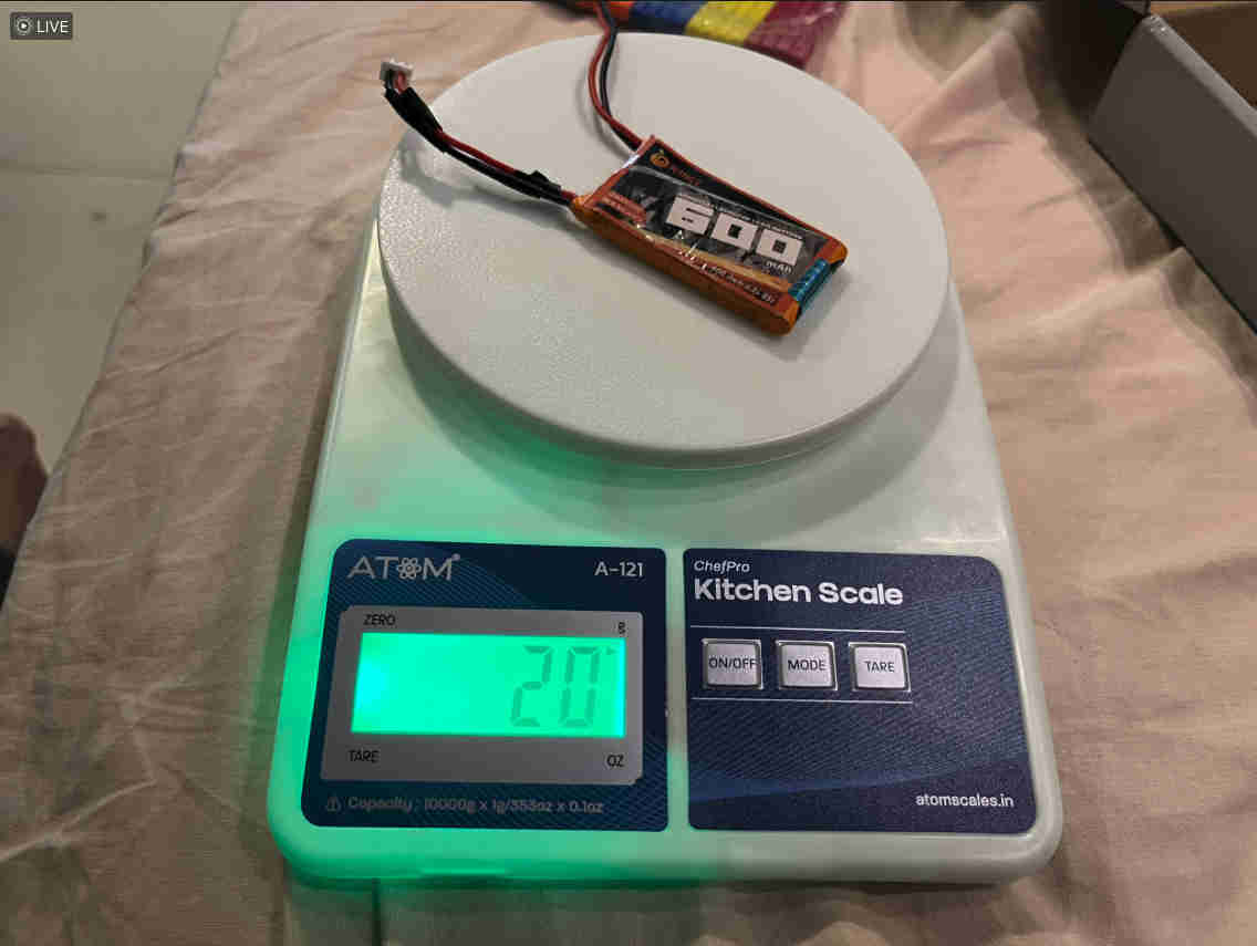
i started by weighing all components on each side.
once I knew a value, i started looking for things i could add and subtract easily and simething that was dense enough to have weight and not move and rattle around
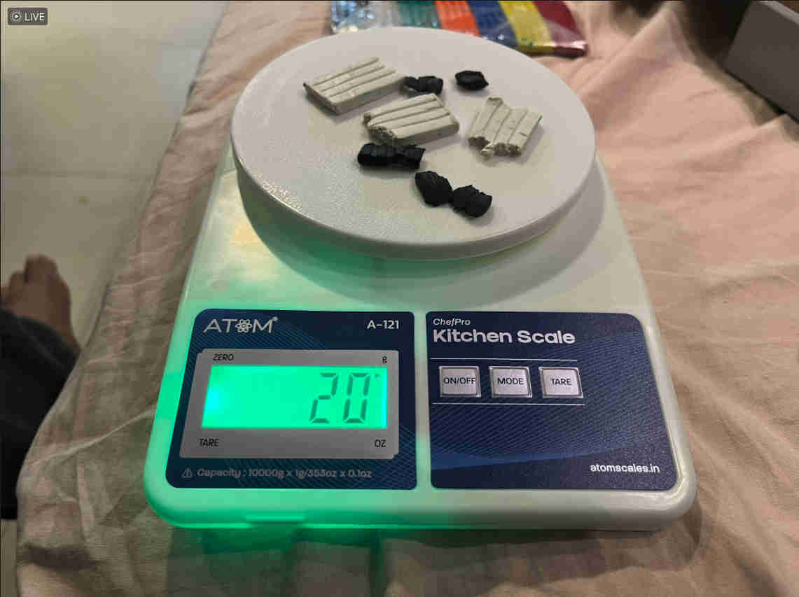
clay came to be an obvious and beutiful choice.
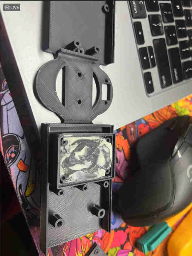
i printed a new model to house clay as such and enclose it
IT WORKED BEAUTIFULLY.
This was the stable spin after the clay edit.
Electronics Design 2
The pcb was redesigned with ports and pads in orientation accroding to the deisgn.
this was the soldered design. With the wifi antenna to boost range.
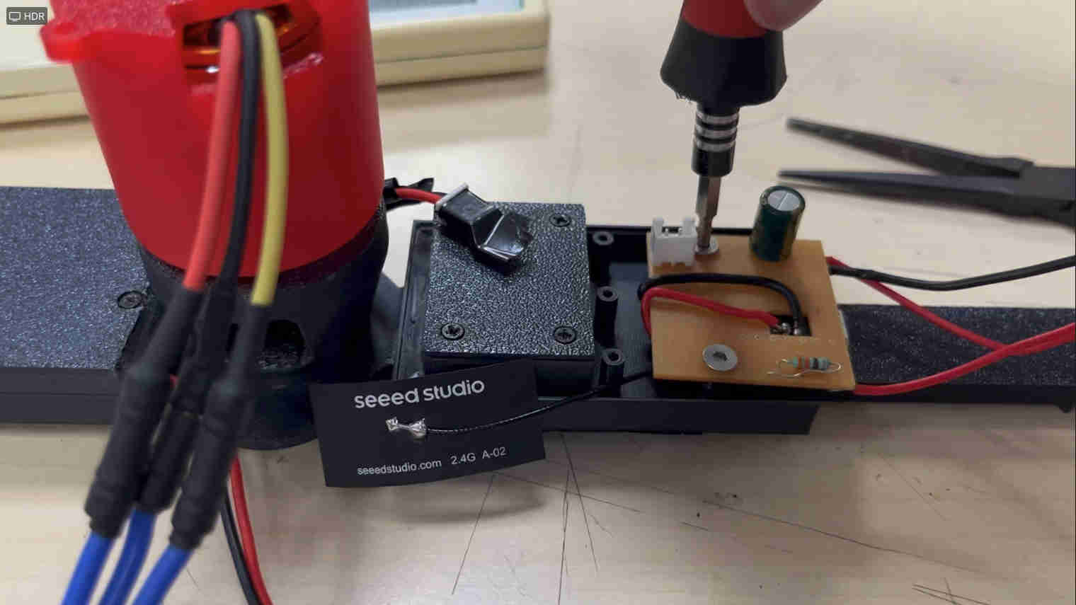
This is how the board fit onto the blade.
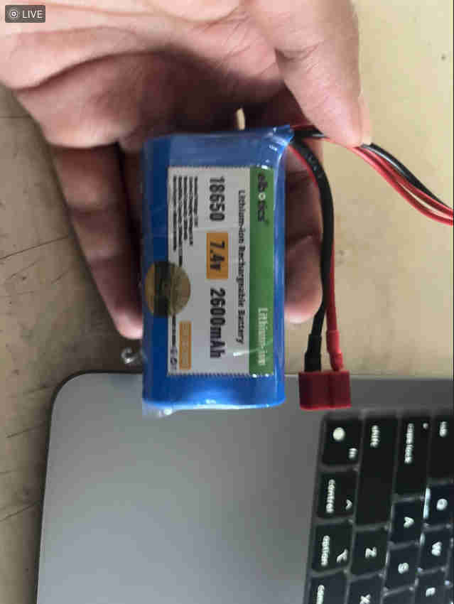
This is the power supply I used for the drone motor. Which lasted about 40 minutes of continuous running.
my actual plan was to have a pcb on the bas e with the esp32 sense camera module, and it shoots out to the
Interface Through Laptop
The entire interface and info related tohow the code works can be found in interface week here
FINAL DEMO
insane display but a camera just does not capture it well.
live feed to hologram worked brilliant with a plain bakcground and contrasting clothes and colours.
all in all a great project with tonnes of learnings and still the heart isnt satisfied
Learnings and Future Prospects
AND WITH THAT
Thankyou fab ❤️