Week 12 · Mechanical Design & Machine Design
A.k.a. we took apart a hoverboard and somehow ended up with a little green robot 🛹➡️🤖
🪛 Overview
This was a group week. The brief was to design a machine that includes mechanism + actuation + automation + application, build the mechanical parts and operate it manually, then actuate and automate it.
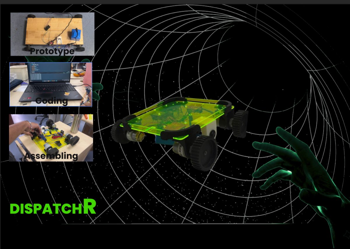
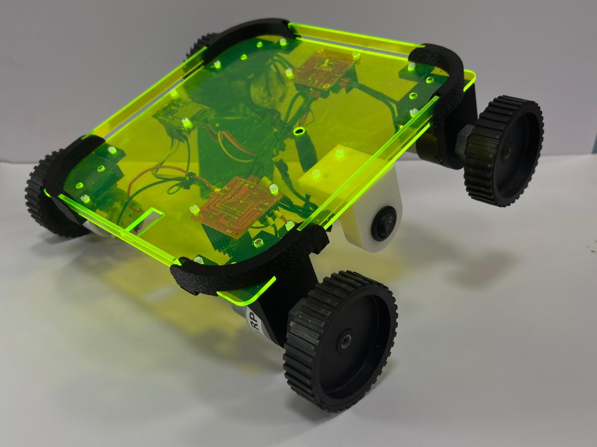
We started out planning to rebuild a hoverboard, and ended up with DispatchR, a wireless, remote-controlled drive robot: four geared DC motors, an L298N motor driver and an ESP32 on an acrylic chassis, driven over ESP-NOW from a handheld controller.
| Brief | Our machine |
|---|---|
| Mechanism | Four-wheel chassis with motor mounts and shaft couplings |
| Actuation | Geared DC motors driven by an L298N motor driver |
| Automation | ESP32 receiving commands and switching the motor driver |
| Application | Remote-controlled robot for point-to-point delivery indoors |
👥 Group Assignment
The full build is documented on the group page and on my teammates' pages:
🔗 Group Assignment: Machine Design
🔗 Vignesh Shetty: Week 12
🙋 My Contribution
| Area | What I did |
|---|---|
| ⚡ PCB | Designed the controller PCB in EasyEDA and milled it |
| 🗺️ Planning | Helped plan the build: teardown, redesign, and how the parts fit together |
| 🔧 Assembly | Helped assemble the frame, motors and electronics |
The rest of the team worked across the teardown, frame, wiring and programming. Tasks were rotated rather than fixed, so everyone touched most of the build.
🗺️ How the Project Evolved
 PART 1: Hoverboard          PART 2: Own drive system      FINAL: RC robot
 ┌──────────────────┐        ┌──────────────────────┐      ┌──────────────────────┐
 │ Tear down        │        │ DC motor (too weak)  │      │ 4 geared DC motors   │
 │ hoverboard       │  ───▶  │ → geared DC motors   │ ───▶ │ L298N + ESP32        │
 │ Reuse hub motor  │        │ L298N + ESP32        │      │ Acrylic chassis      │
 │ Wood + aluminium │        │ Wiring + mounts      │      │ ESP-NOW controller   │
 │ frame            │        │                      │      │ (my PCB)             │
 └──────────────────┘        └──────────────────────┘      └──────────────────────┘
| Problem | What we changed |
|---|---|
| The hoverboard's motors and sensors were tied to its own master control board, so we couldn't drive them on their own | Built our own drive system with a separate motor driver and microcontroller |
| A plain DC motor didn't have enough torque to carry the weight | Switched to geared DC motors |
| The heavy wooden base restricted the wheels | Replaced it with a lighter acrylic sheet |
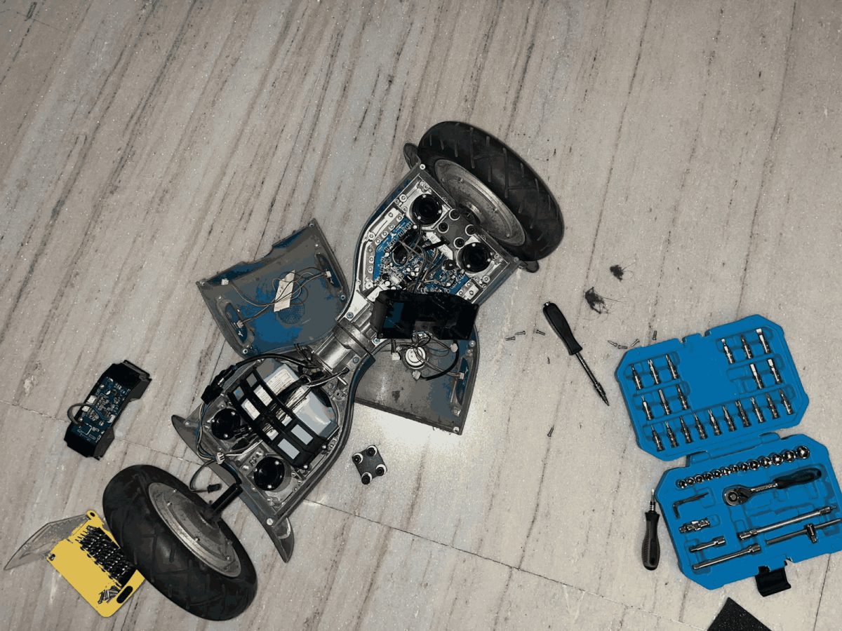
🛹 Part 1: Taking Apart the Hoverboard
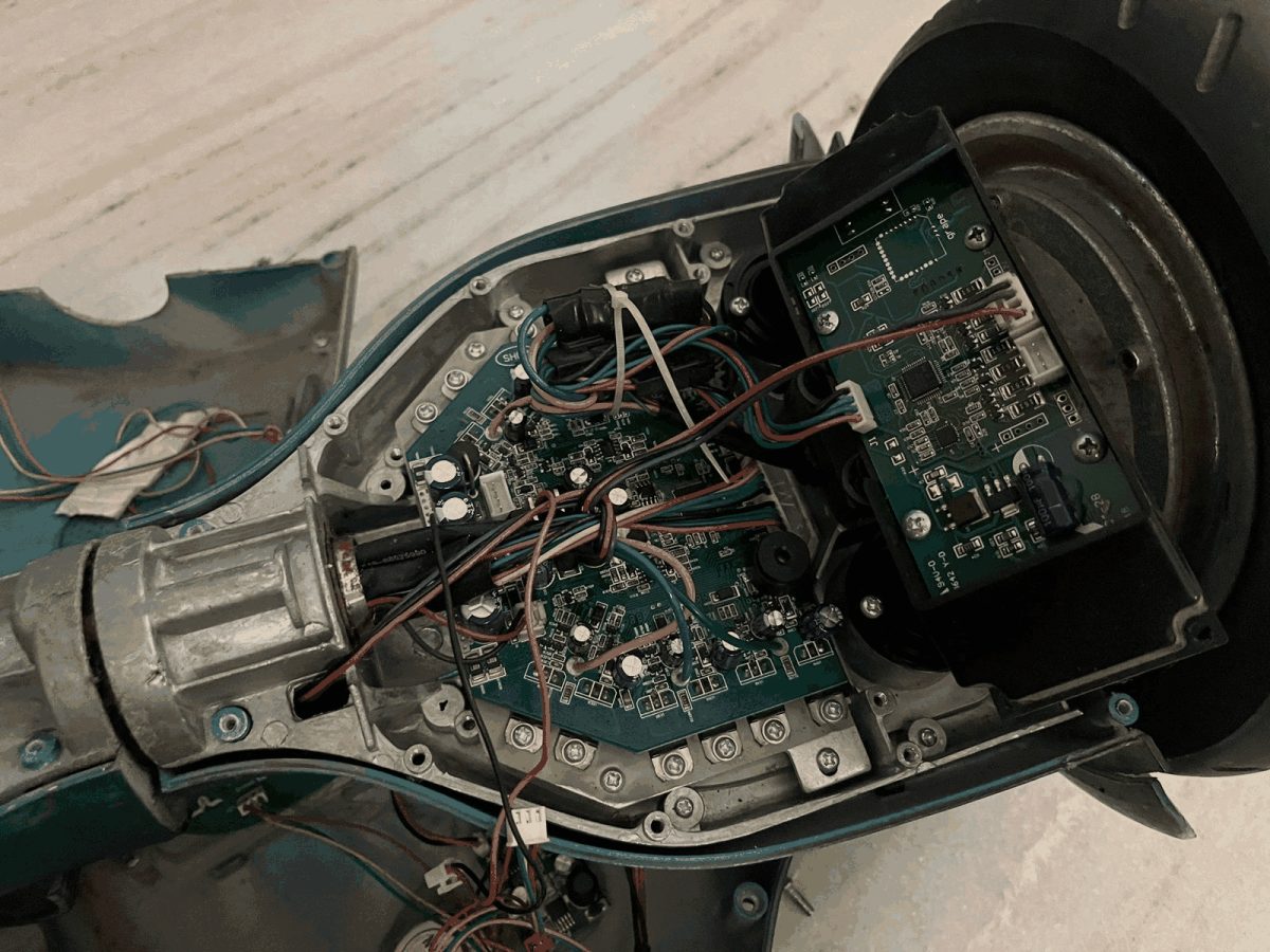
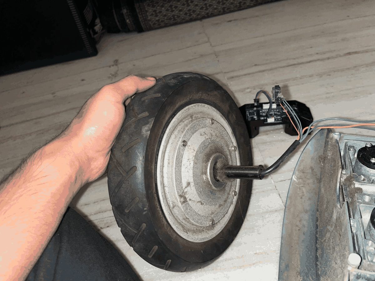
The plan was to reuse a hoverboard's hub motor (a motor built into the wheel), since sourcing one separately was hard. We opened it up to see what we were working with.
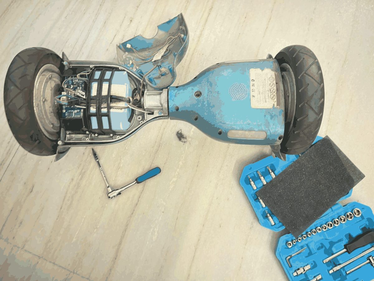
🔹 Planning
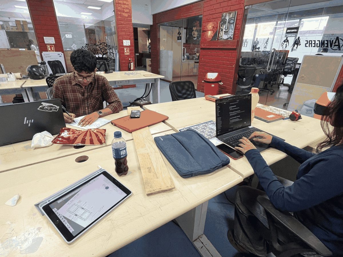
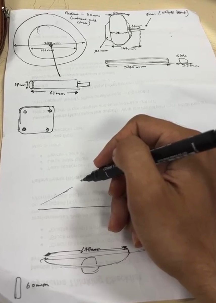
With the parts laid out, we sat down to plan how to turn them into a new machine: what to keep, how to mount the motor, and what size the frame should be. I worked on this planning stage with the team.
🔹 Testing and the first frame
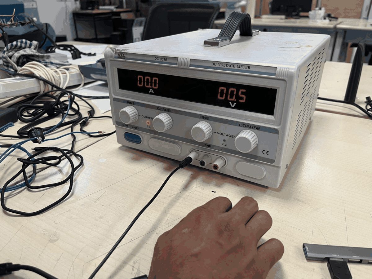
We bench-tested the hub motor on a DC power supply, then built a first frame out of aluminium extrusion and wood and test-fitted the motor.
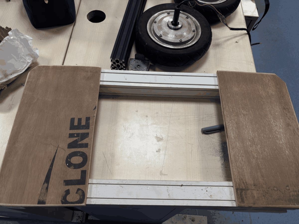
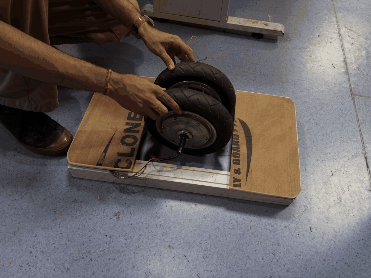
This is where we hit the wall: the hub motor couldn't be driven without the hoverboard's own control board. So we changed direction.
⚙️ Part 2: Our Own Drive System
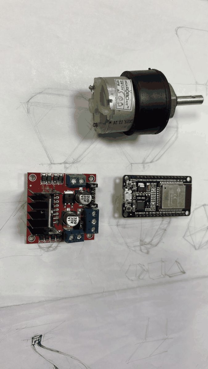
Instead of fighting the hoverboard electronics, we built a simple drive system we fully controlled:
 Controller (ESP32 + my PCB)
        │  ESP-NOW (wireless)
        ▼
 ESP32 on the robot ──GPIO──▶ L298N motor driver ──▶ geared DC motors ──▶ wheels
                                   ▲
                             12 V supply
| Component | Job |
|---|---|
| ESP32 (robot) | Receives commands over ESP-NOW and sets the driver's inputs |
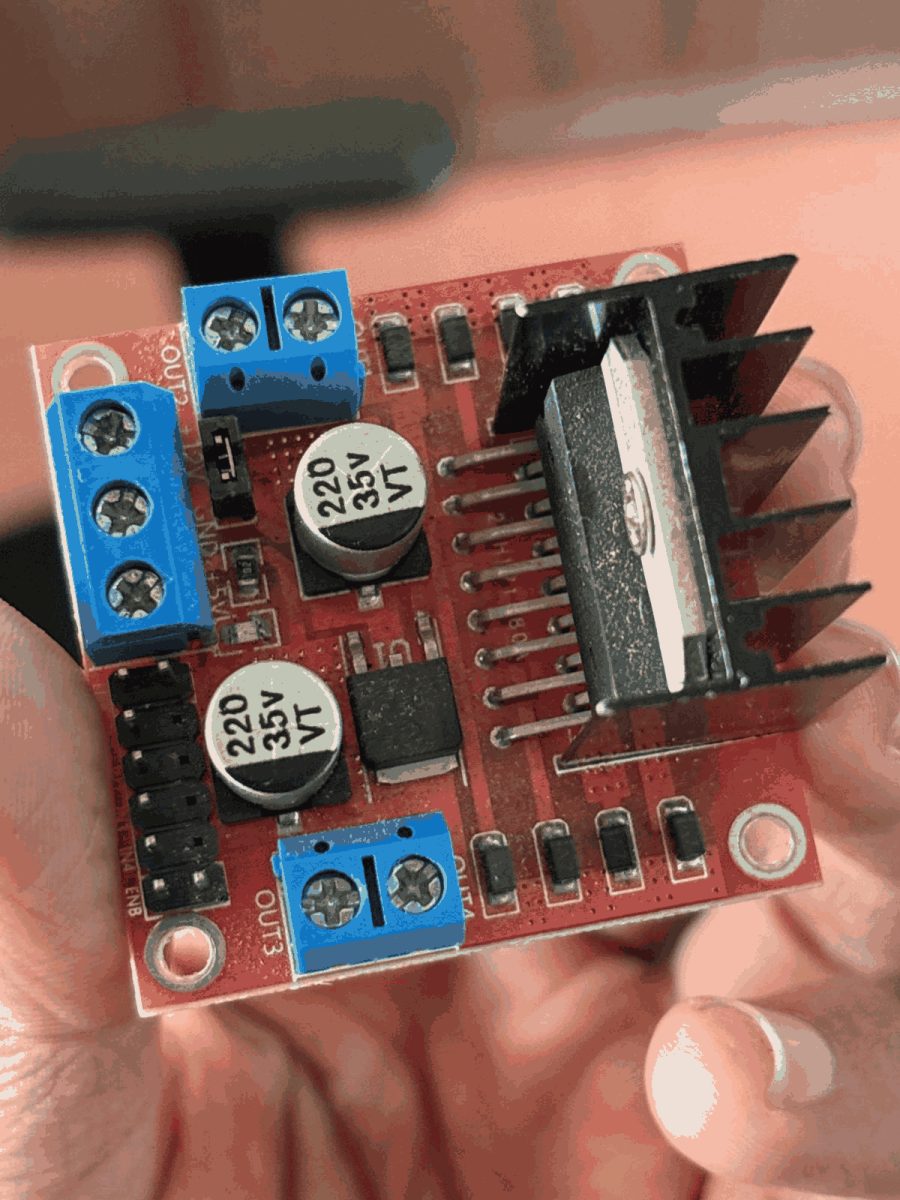
| L298N | Dual H-bridge: switches the motor current and direction (IN1–IN4) |
| Geared DC motors | Enough torque to move the robot's weight |
| ESP32 (controller) | Reads the buttons and sends commands to the robot |
The L298N's IN1–IN4 pins set the direction of each motor. We didn't use the ENA/ENB enable pins, because we weren't doing PWM speed control at this stage: the motors are either on or off in each direction.
⚡ The Controller PCB (My Part)
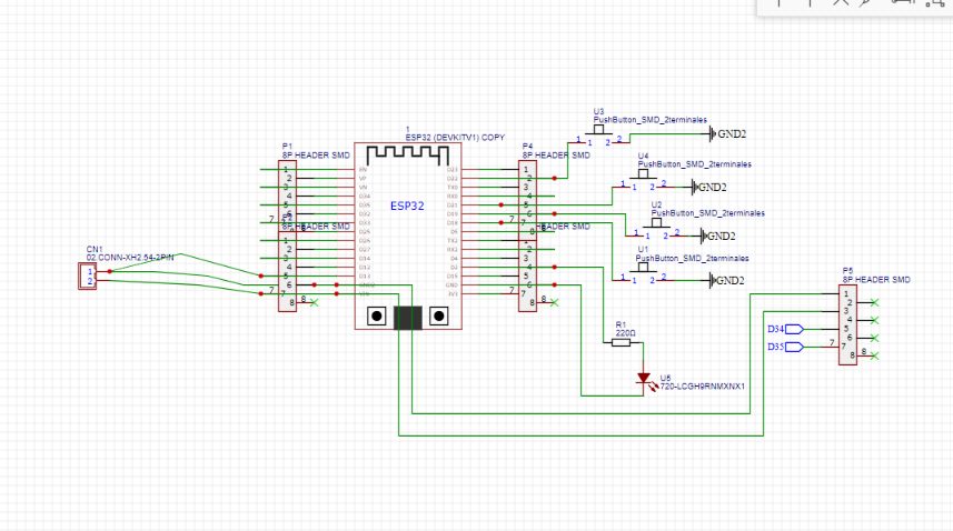
My main job was the controller board: the handheld side that sends commands to the robot. I designed it in EasyEDA and then milled it on the lab's PCB mill.
🔹 Version 1: first schematic
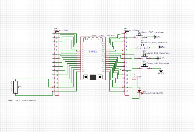
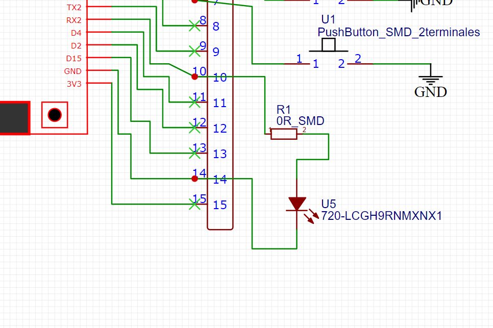
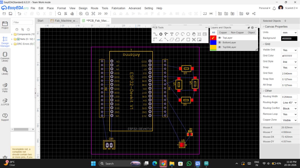
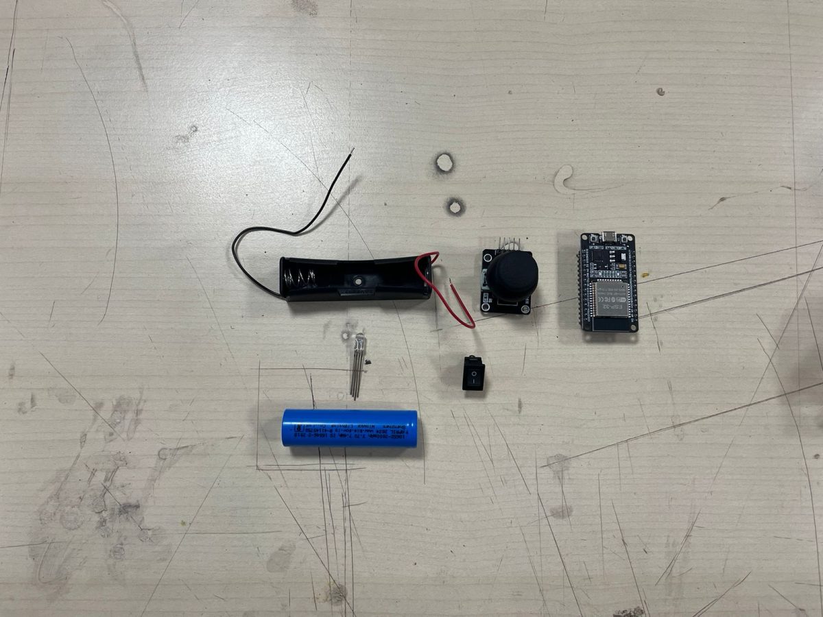
The first version put an ESP32 DevKit V1 between two 15-pin headers, with four push buttons, an LED and an 18650 Li-ion battery holder drawn straight onto the board so the controller could run on its own battery.
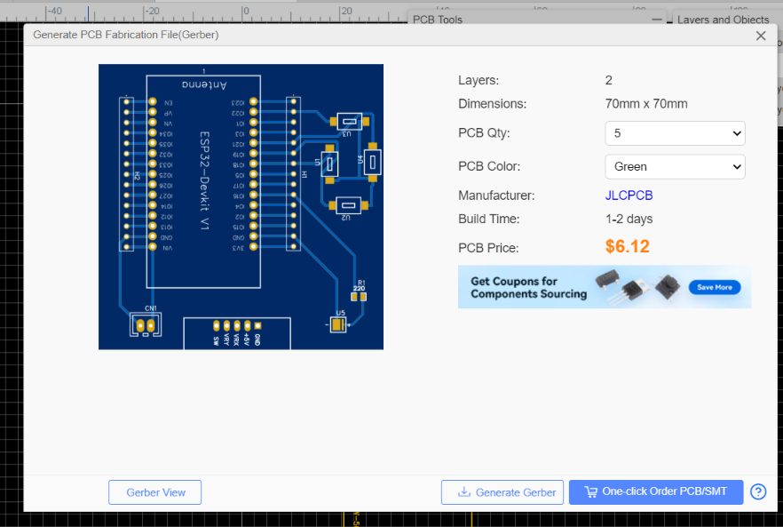
🔹 Version 2: final board
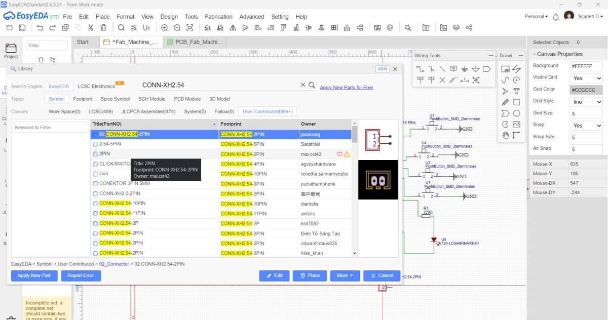
For the final version I moved the battery off the board (it plugs into a 2-pin connector instead), switched to 8-pin female headers so the ESP32 can be pulled out and reused, and added a header for a joystick.
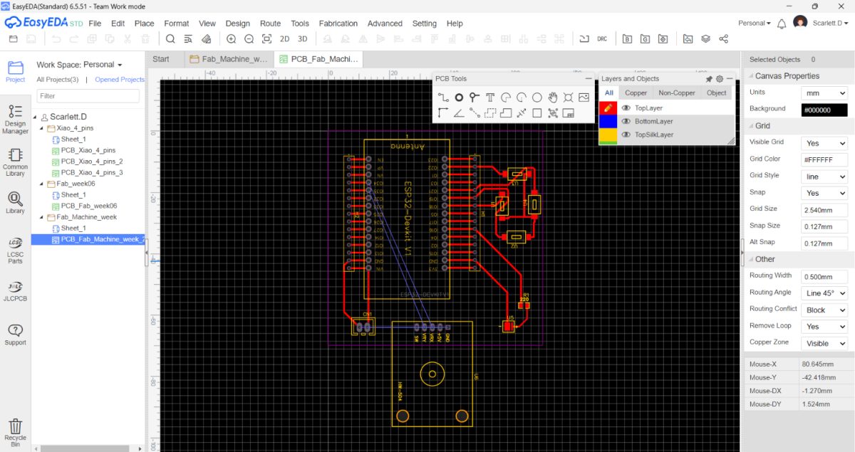
| Ref | Part | Purpose |
|---|---|---|
| P1–P4 | 8-pin female headers (2.54 mm) | Socket for the ESP32 DevKit V1 |
| U1–U4 | SMD push buttons | Four control inputs, each switching an ESP32 pin to GND |
| U5 + R1 | SMD LED + 220 Ω resistor | Status indicator |
| CN1 | XH 2.54 mm 2-pin connector | Battery / power input |
| Joystick header | 5 pins: SW, VRY, VRX, +5V, GND | Joystick module (two analog axes + push switch) |
| Version 1 | Version 2 | |
|---|---|---|
| ESP32 mounting | 15-pin headers | 4 × 8-pin female headers |
| Power | 18650 holder on the board | External battery via CN1 |
| Inputs | 4 buttons | 4 buttons + joystick header |
| LED resistor | 0 Ω placeholder | 220 Ω |
The buttons are wired between an ESP32 pin and ground, so the code can use the internal pull-up resistors. That means fewer parts on the board, and a button reads LOW when it's pressed.
🔹 Milling
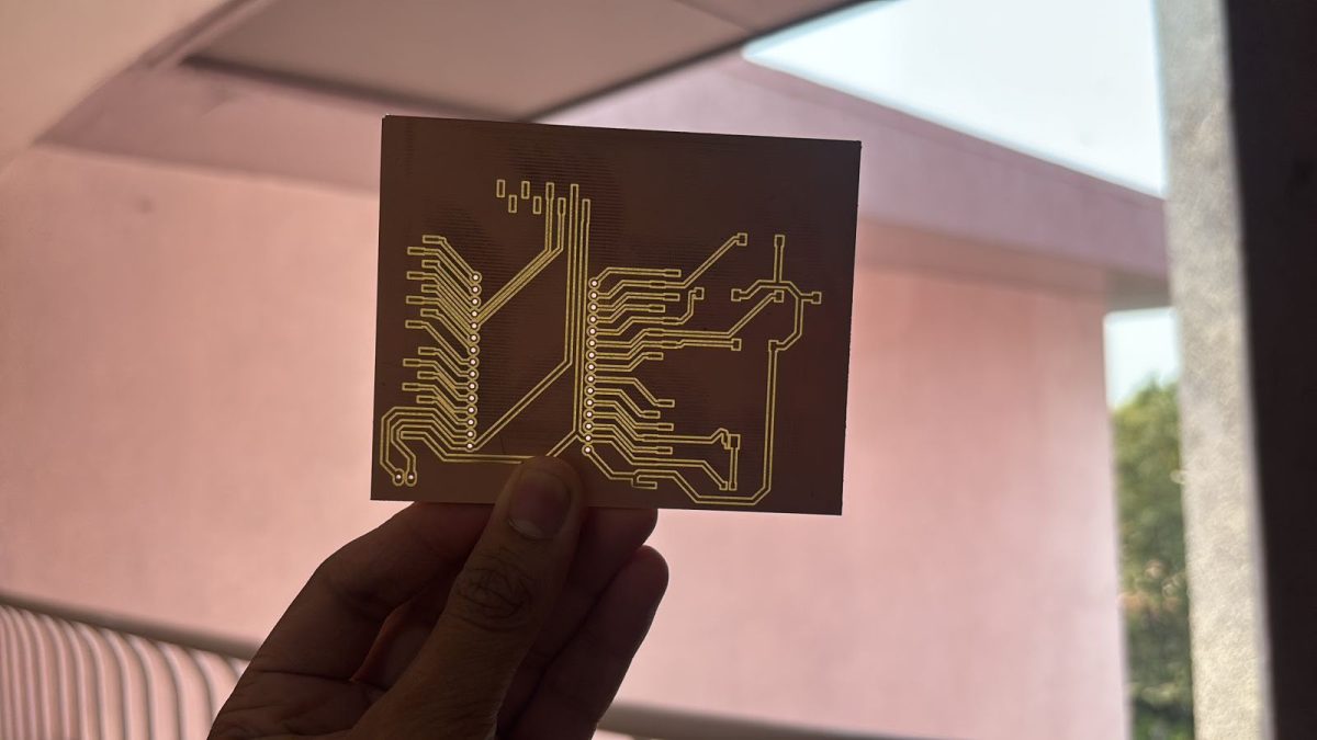
I exported the Gerbers from EasyEDA and milled the board on the lab's monoFab, using the same workflow as in Week 8: Electronics Production.
🔹 The controller
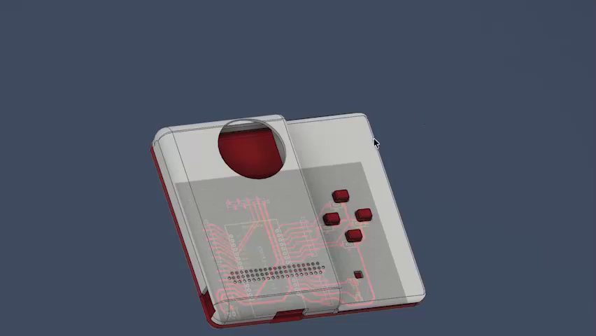
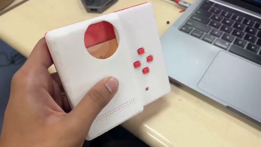
The board went into a 3D-printed handheld enclosure, with four red buttons and an opening for the joystick.
🔧 Assembly
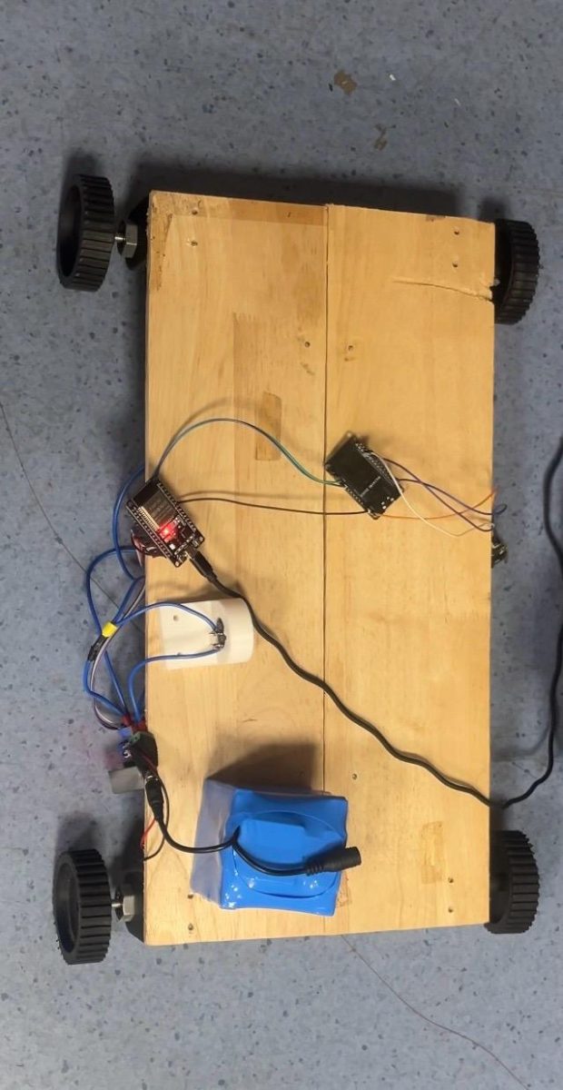
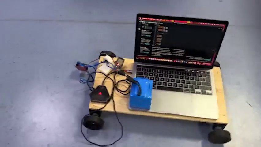
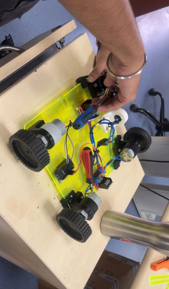
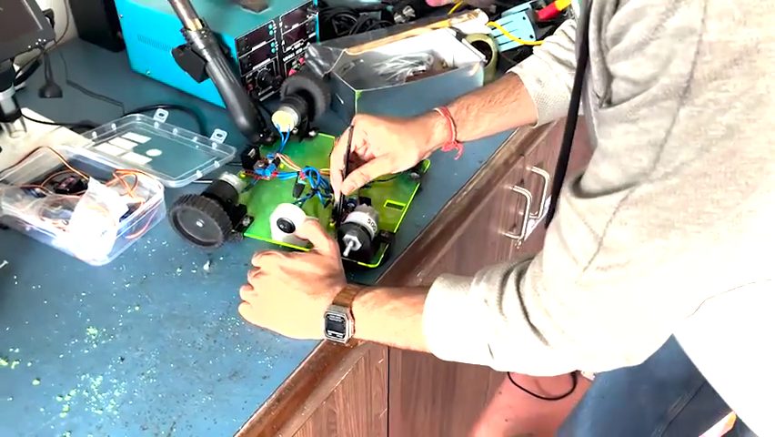
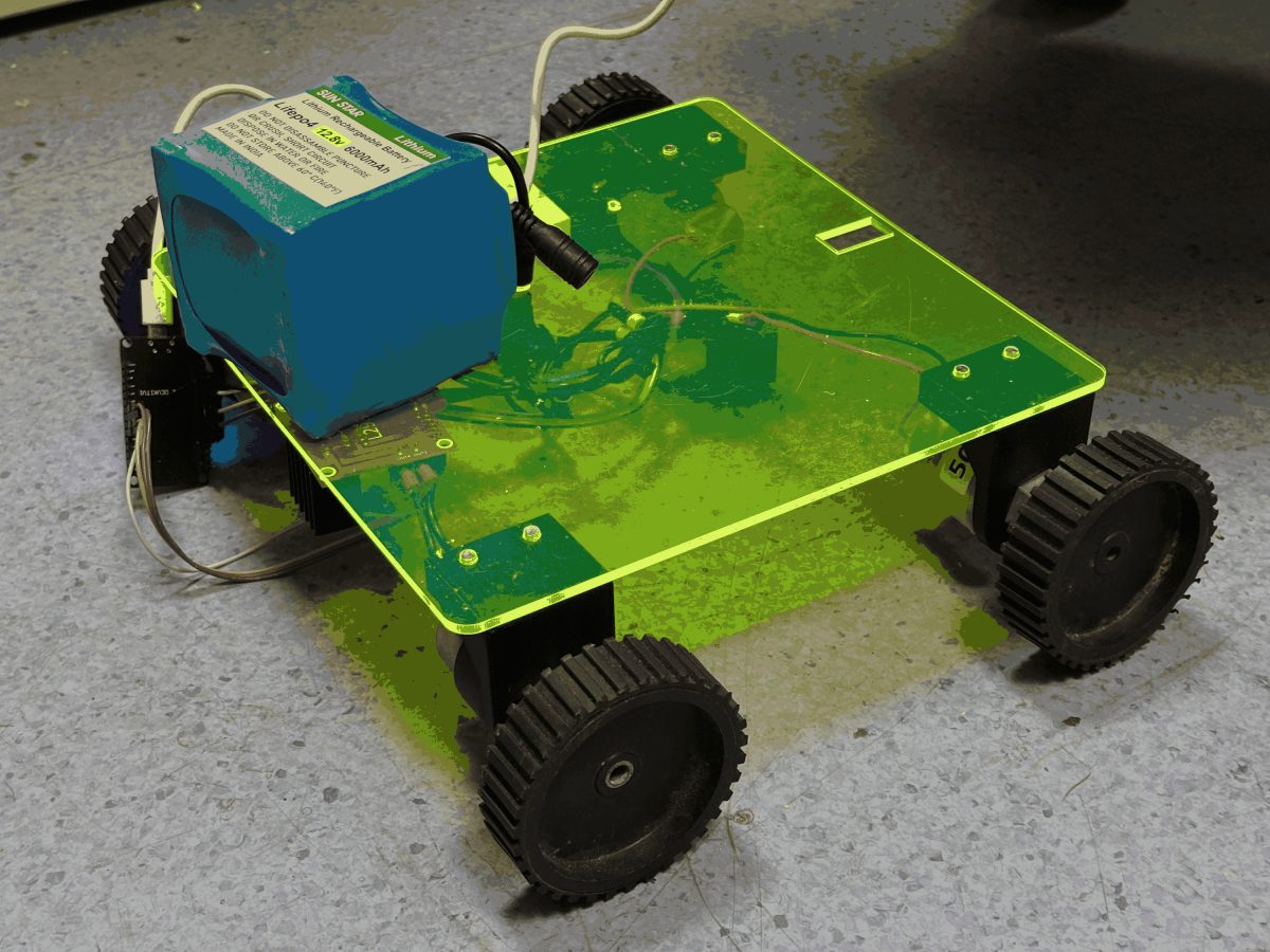
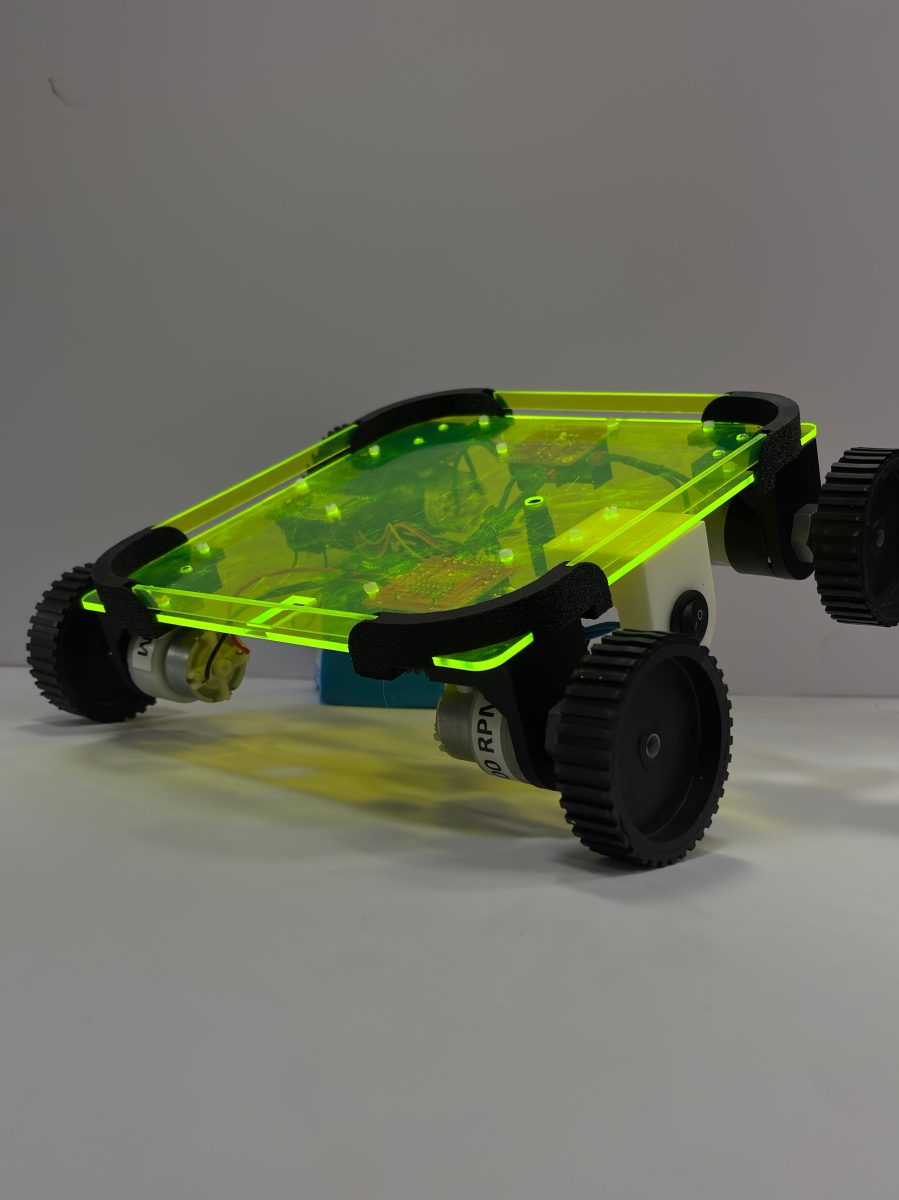
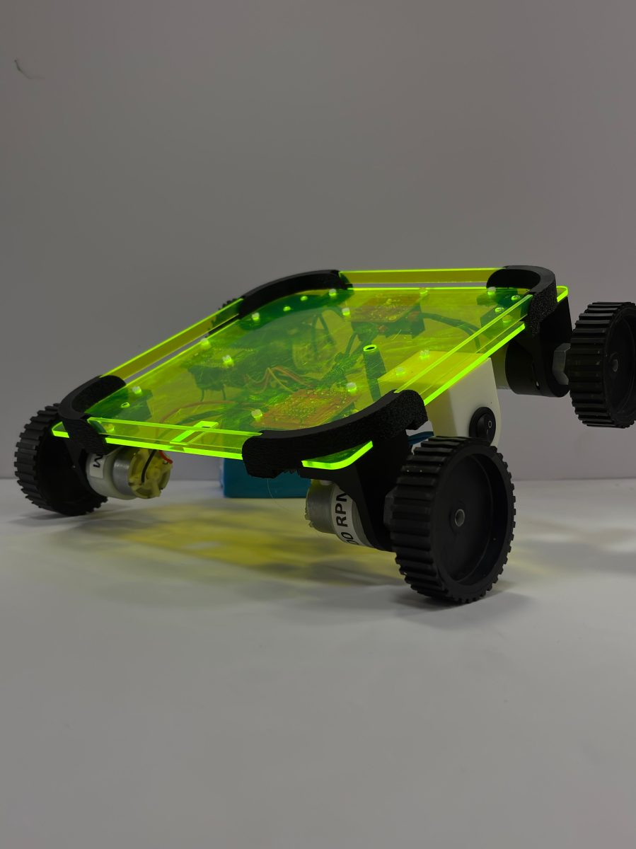
We first tested the drive system on a wooden base, coding and testing directions while it was still on the bench. The wooden base turned out to be too heavy and got in the way of the wheels, so it was replaced with a green acrylic sheet. The four motors and wheels were mounted underneath, with the electronics on top.
🔹 Assembly order
- • Solder wires onto the motor terminals, add heat shrink and crimp ferrules
- • Mount the motors and wheels on the chassis
- • Wire the motors to the L298N outputs
- • Connect the L298N's IN1–IN4 to the ESP32 and share the ground
- • Power up, test each direction, then pair the controller over ESP-NOW
🤖 Final Machine
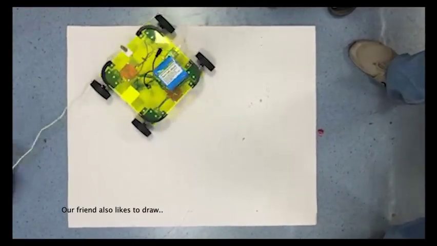
The finished DispatchR drives in all directions from the wireless controller. As a bonus, we attached a marker to it and let it draw on paper as it drove around 🖍️.
🎬 The DispatchR film
✨ What I Learned
- • Reusing consumer hardware sounds easy, but its parts are often locked to its own control board
- • Torque matters more than speed when a motor has to move real weight, which is why we used geared motors
- • Socketing the dev board on headers makes a PCB much easier to debug and reuse
- • Using internal pull-ups for buttons keeps the board simpler
- • A second PCB version is normal: moving the battery off the board and adding a joystick header made it far more flexible
- • Changing direction early (hoverboard → own drive system) saved us more time than forcing the first plan
- • In a group build, planning and clear interfaces (which board sends what, which pins go where) keep everyone in sync
📁 Design Files
Controller schematic, EasyEDA (.json)Controller PCB layout, EasyEDA (.json)
Controller PCB Gerbers (.zip)