Week 10: Output Devices
A.k.a. teaching tiny blue servos to pull strings 🧵🎭
🪛 Overview
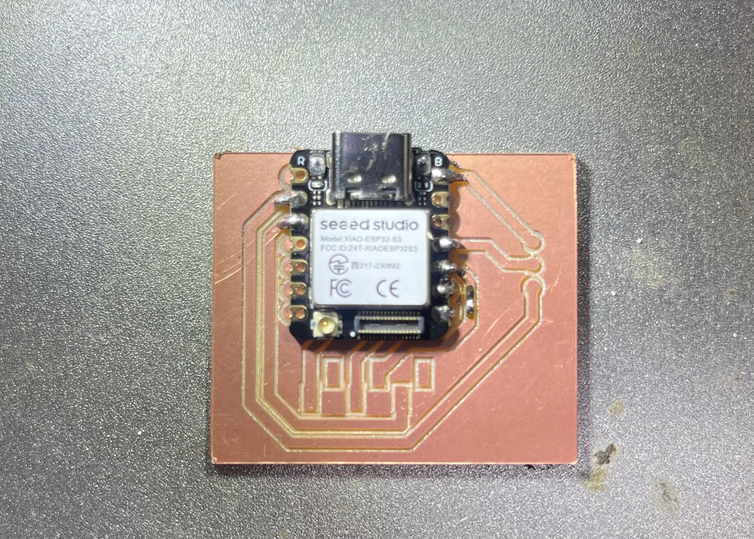
My output devices are SG90 micro servos, the motors that pull the strings of my final project puppet, Sandy. I started with one servo on an Arduino, moved to the ESP32, and ended up driving all the joints through a PCA9685 servo driver connected to my custom XIAO ESP32-S3 board.
- • Step 1: one servo on an Arduino, with "moods" sent over Serial
- • Step 2: one, then two servos straight from the ESP32
- • Step 3: all the joints through the PCA9685, from my own board
👥 Group Assignment
The group assignment was to measure the power consumption of an output device.
🔗 View Group Assignment Documentation
⚙️ How a Servo Works
A hobby servo has a small motor, a gearbox and a position sensor inside. You don't tell it to "spin"; you tell it which angle to go to. It listens for a pulse every 20 ms (50 Hz), and the width of that pulse sets the angle:
| Pulse width | Angle |
|---|---|
| ~0.5 ms | 0° |
| ~1.5 ms | 90° |
| ~2.5 ms | 180° |
The SG90 has 3 wires: brown (GND), red (+5V) and orange (signal).
1️⃣ One Servo, Three Moods
I started on an Arduino Uno with the Servo library. To explore how movement can show emotion
(which is the whole point of a puppet), I sent a mood over Serial and the servo acted it out:
- • CALM: slow sway between 70° and 110°
- • HAPPY: quick bounces between 60° and 120°
- • ANGRY: random, jerky jumps anywhere between 20° and 160°
else if (incomingData == "ANGRY") {
  for (int i = 0; i < 8; i++) {
    int randomPos = random(20, 160);
    myServo.write(randomPos);
    delay(random(50, 150));
  }
}
2️⃣ Moving to the ESP32
The ESP32 doesn't use the Arduino Servo library, so I generated the PWM signal myself. First with the ESP32's
LEDC PWM peripheral at 50 Hz with 8-bit resolution, where a duty value of 6, 19 and 32 gave left, centre and right:
const int servoPin = 18;

void setup() {
  ledcAttachChannel(servoPin, 50, 8, 0);   // 50 Hz, 8-bit
}

void loop() {
  ledcWrite(servoPin, 6);   delay(1000);   // LEFT
  ledcWrite(servoPin, 19);  delay(1000);   // CENTER
  ledcWrite(servoPin, 32);  delay(1000);   // RIGHT
}
Then two servos, by writing the pulses by hand: map the angle to 500–2500 µs, set the pin HIGH for that long, then LOW. I reused the calm / happy / angry idea with the two servos moving against each other.
void writeServo(int pin, int angle) {
  int pulseWidth = map(angle, 0, 180, 500, 2500);
  digitalWrite(pin, HIGH);
  delayMicroseconds(pulseWidth);
  digitalWrite(pin, LOW);
  delay(20);
}
3️⃣ All the Joints: PCA9685
Generating pulses by hand doesn't scale: the board is stuck waiting for each pulse. So for the final project I used a PCA9685, a 16-channel, 12-bit PWM driver. The XIAO just tells it the positions over I²C, and the PCA9685 keeps all the servo signals running by itself.
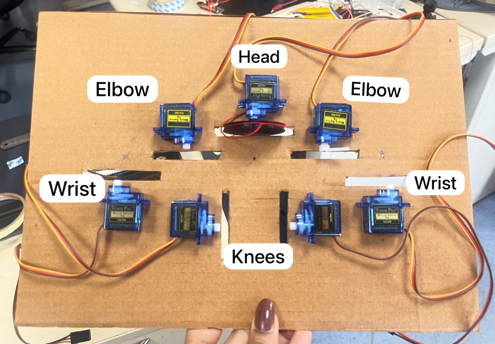
🔹 Wiring
| XIAO ESP32-S3 | PCA9685 |
|---|---|
| SDA (D4) | SDA |
| SCL (D5) | SCL |
| 3.3V | VCC (logic) |
| 5V | V+ (servo power) |
| GND | GND (shared) |
🔹 Channel map (final version)
| Joint | PCA9685 channel |
|---|---|
| Right wrist | CH2 |
| Left wrist | CH13 |
| Left knee | CH15 |
| Right knee | CH0 |
| Head | CH5 |
🔹 The code
The PCA9685 runs at 50 Hz, and each period is split into 4096 steps. A pulse of 150 steps is 0° and 600 steps is 180°,
so an angle is just mapped onto that range. smoothMove() then steps 1° at a time so the strings don't get yanked.
#define SERVO_FREQ      50
#define SERVO_MIN_PULSE 150   // 0°
#define SERVO_MAX_PULSE 600   // 180°

int angleToPulse(int angle) {
  return map(angle, 0, 180, SERVO_MIN_PULSE, SERVO_MAX_PULSE);
}

void setServo(int ch, int angle) {
  angle = constrain(angle, 0, 180);
  pca.setPWM(ch, 0, angleToPulse(angle));
  currentAngles[ch] = angle;
}

void smoothMove(int ch, int target, int stepDelay = 10) {
  int current = currentAngles[ch];
  int step = (target > current) ? 1 : -1;
  while (current != target) {
    current += step;
    setServo(ch, current);
    delay(stepDelay);
  }
}
Each joint uses three positions: limp (0°, string slack), neutral (90°) and full (180°, string pulled).
Poses like wave, bow, nod and dance are just sequences of smoothMove() calls.
🔋 Powering the Servos
Servos draw a lot more current than the microcontroller, especially when several move at once. So the servos get their own external 5V supply on the PCA9685's V+ pin, while the XIAO only powers the PCA9685's logic (3.3V on VCC). All grounds are shared so the signals have the same reference. The full power budget is in Week 15 · System Integration.
✨ What I Learned
- • A servo is controlled by pulse width, not by voltage or speed
- • The same motor can look calm, happy or angry depending only on timing and range
- • A dedicated driver like the PCA9685 frees the microcontroller to do other things (like run Wi-Fi)
- • Servos need their own power supply and a shared ground
- • Moving 1° at a time looks much more natural than jumping straight to the target
📁 Design Files
Arduino: one servo, three moods (.ino)ESP32: one servo with LEDC (.ino)
ESP32: two servos, manual pulses (.ino)
Final: PCA9685 puppet controller (.ino)