Week 4: Embedded Programming.
A.k.a. making two ESP32s gossip through buttons and LEDs ✨📡
🪛 Overview
This week focused on programming embedded systems and understanding how microcontrollers interact with inputs, outputs, and communication systems.
For this assignment, I created a bidirectional push-button interaction system using ESP32 boards. Pressing a button on one side triggered an LED response, creating a simple communication-based interaction between input and output devices.
👥 Group Assignment
As part of the group assignment, we explored embedded programming workflows, microcontroller architectures, and communication methods. The complete group documentation can be found here:
🔗 View Group Assignment Documentation
🛠️ Tools + Components Used
- • ESP32
- • Push Buttons
- • LEDs
- • Jumper Wires
- • Breadboard
- • Arduino IDE
📄 ESP32 Datasheet Exploration
Before programming, I explored parts of the ESP32 datasheet to understand:
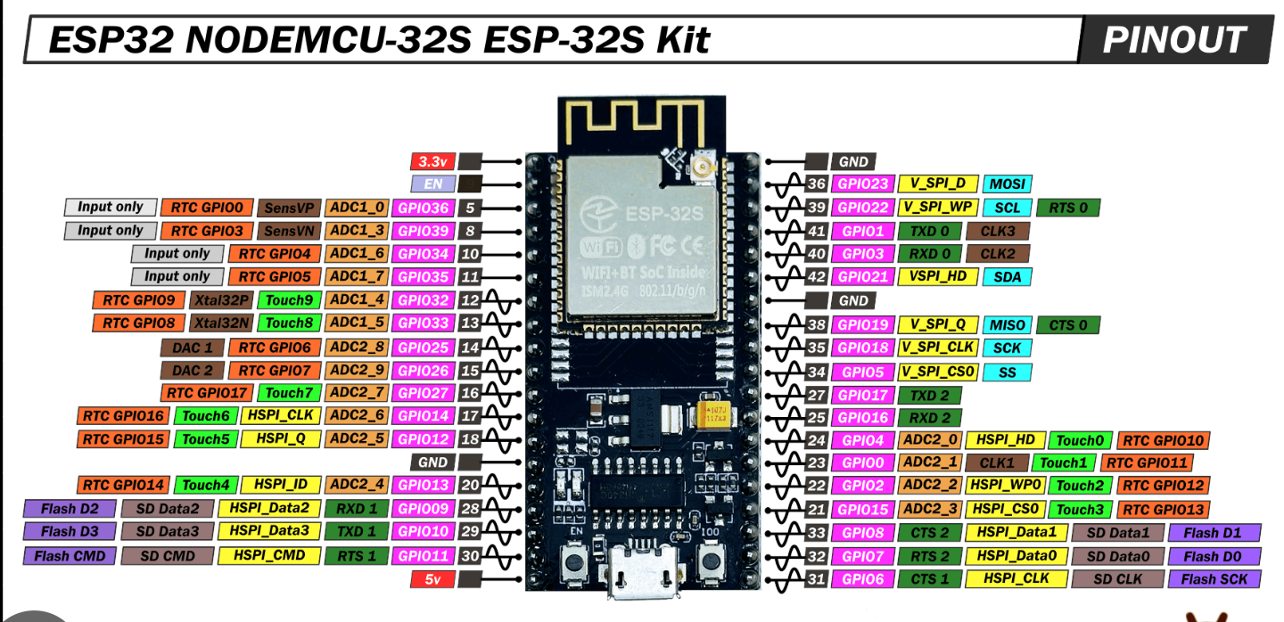
- • GPIO pins
- • Input/output functionality
- • Voltage levels
- • Communication protocols (e.g., I2C, SPI)
- • PWM capabilities
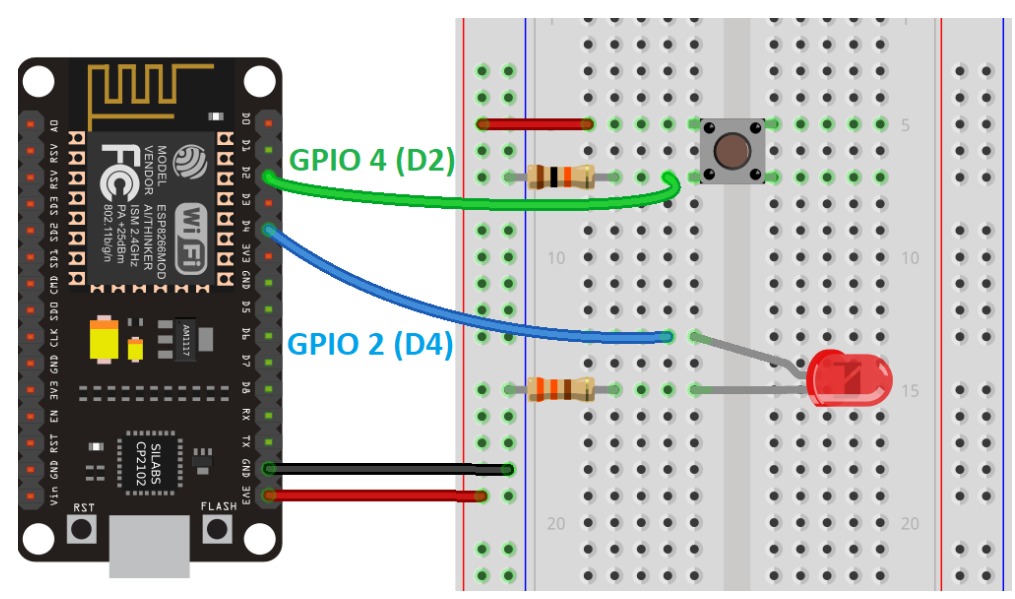
🔌 Building the Circuit
🔹 Input Device: Push Button
The push button was used to send a digital signal to the ESP32 whenever it was pressed.
🔹 Output Device: LED
The LED was used as a visual indicator to display the state of the system.
When the button is pressed, the ESP32 reads the input and changes the LED state accordingly.
- • Connected the push button to the ESP32
- • Connected the LED to an output pin
- • Configured GPIO pins in the Arduino IDE
- • Uploaded and tested the code
- • Verified the interaction through repeated testing
📡 Understanding ESP-NOW
Instead of connecting the boards using wires, I used ESP-NOW, a lightweight wireless communication protocol developed by Espressif.
ESP-NOW allows ESP boards to communicate directly without needing a WiFi router. This made it possible to send button states wirelessly between two boards.
The communication flow looked something like this:
Push Button → ESP32 → ESP-NOW → ESP32 → LED
In other words: wireless button gossip. ✨
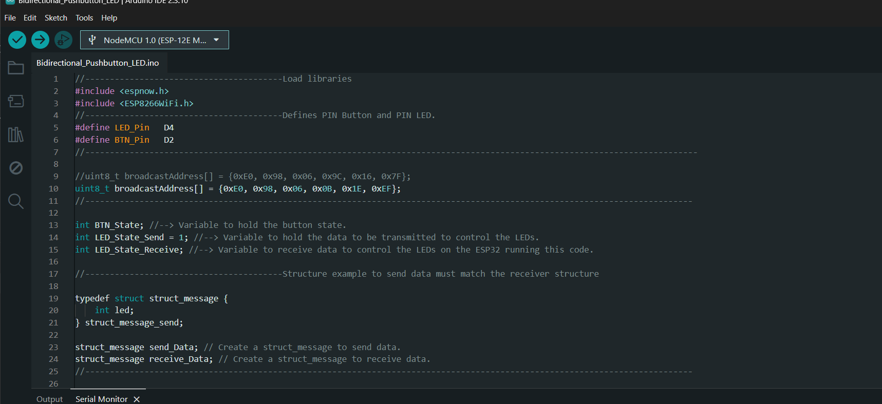
💻 Programming Logic
The program continuously monitors the state of the push button. Whenever the button is pressed, the ESP32 toggles the LED state and sends that value to the paired board using ESP-NOW.
The receiving board listens for incoming messages and updates its LED accordingly.
Key parts of the program:- Reading button input using GPIO pins
- Toggling LED states
- Sending data using ESP-NOW
- Receiving data through callback functions
- Updating outputs based on received messages

😭 Things That Went Wrong
- Incorrect MAC addresses prevented communication between boards.
- Wiring mistakes made debugging unnecessarily exciting.
- Sometimes the LED wasn't responding because of code issues.
- Sometimes it wasn't responding because the wires had decided to betray me.
The Serial Monitor became my best friend during debugging.
🎥 Final Demonstration
After configuring both boards and uploading the code, the system successfully transmitted button states wirelessly using ESP-NOW.
Pressing the button on one board triggered a response on the paired board, demonstrating communication between two embedded systems.
✨ What I Learned
- How wireless communication works between ESP boards.
- How to use GPIO pins for inputs and outputs.
- The importance of debugging both hardware and software.
- How callback functions are used in embedded systems.
- That a blinking LED can somehow consume several hours of your life. (╥﹏╥)
📂 Source Code
The complete Arduino code used for the project can be found below:
📂 Source Code