Week 11 · Networking & Communications
A.k.a. two boards, no wires between them, and a button that turns on someone else's light 📡💡
🪛 Overview
The assignment this week: design, build and connect wired or wireless node(s) with network or bus addresses, each with a local input and/or output device.
I built a two-node wireless network using two ESP8266 NodeMCU boards talking over ESP-NOW. Each node has a push button (input) and an LED (output). Pressing the button on one node toggles the LED on the other node, and it works both ways.
| Requirement | How I met it |
|---|---|
| Wireless nodes | 2 × ESP8266 NodeMCU, no wires between them |
| Network addresses | Each node is addressed by its unique Wi-Fi MAC address |
| Local input | Push button on D2 (GPIO4) |
| Local output | LED on D4 (GPIO2) |
👥 Group Assignment
The group assignment was to send a message between two projects.
🔗 View Group Assignment Documentation
📡 Why ESP-NOW?
ESP-NOW is a protocol from Espressif that lets ESP boards send small packets directly to each other using the Wi-Fi radio, but without a router or internet connection. Each board is identified by its MAC address, which works like a house number: you send the message to a specific address, and only that board picks it up.
| ESP-NOW | Regular Wi-Fi (HTTP / WebSocket) | Wired bus (I²C / UART) | |
|---|---|---|---|
| Needs a router? | ❌ No | ✅ Yes (or one board acts as access point) | ❌ No |
| Needs wires between boards? | ❌ No | ❌ No | ✅ Yes |
| Addressing | MAC address | IP address | Bus address / direct link |
| Setup effort | Low | Medium | Low, but boards must be close |
| Good for | Small, fast messages like button presses | Web apps, bigger data | Boards on the same PCB or very near |
Since I only needed to send a tiny on/off message, ESP-NOW was the simplest option. It's also the same family of radio I use for my final project, which runs over Wi-Fi from an ESP32 (see Week 14).
🧩 The Board: ESP8266 NodeMCU
Both nodes use the NodeMCU 1.0 (ESP-12E module). It has Wi-Fi built in, a USB port for programming, and labelled pins that fit straight into a breadboard.
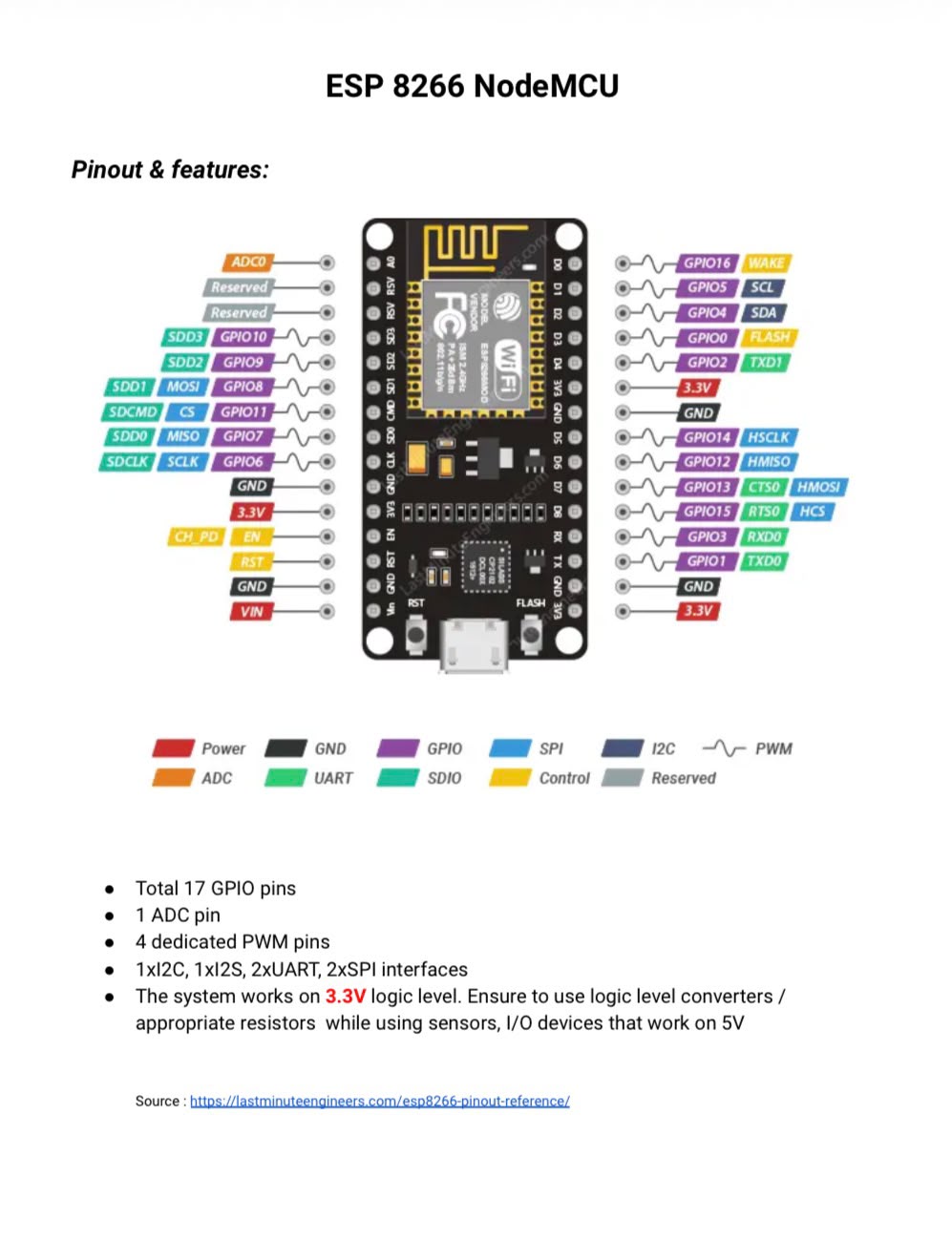
One thing to remember: the board runs at 3.3 V logic, so everything on the breadboard is powered from the 3V3 pin, not 5 V. The pin labels on the board (D2, D4) are not the same as the GPIO numbers the chip uses (GPIO4, GPIO2), so I kept the pinout open while wiring.
🔌 Wiring Each Node
Both nodes are wired the same way, so the same code runs on both. Only the address of the other board changes.
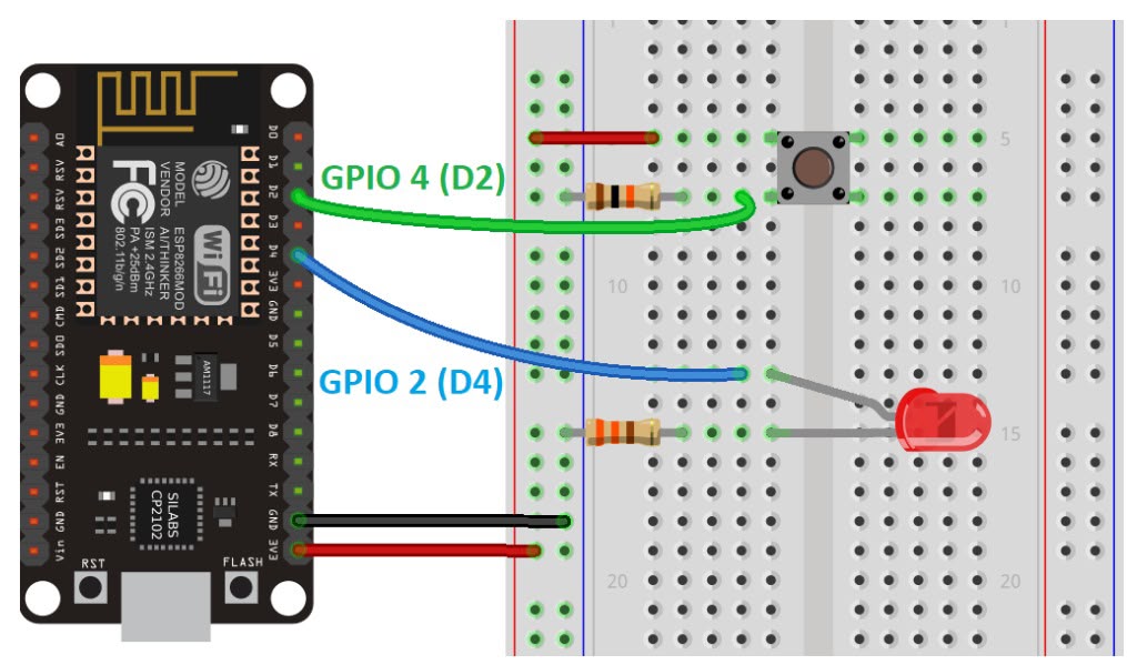
| Component | NodeMCU pin | GPIO | Role |
|---|---|---|---|
| Push button | D2 | GPIO4 | Input |
| LED (+ resistor) | D4 | GPIO2 | Output |
| Power rail | 3V3 | - | 3.3 V supply |
| Ground rail | GND | - | Common ground |
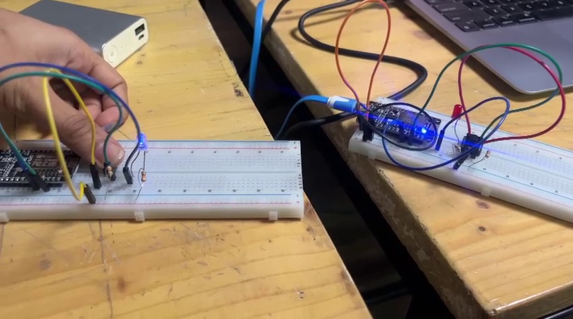
D4 (GPIO2) is also connected to the NodeMCU's small built-in blue LED, so the board itself lights up along with the breadboard LED. That's the blue glow you can see on the boards in the video below.
🏷️ Finding the Addresses
Before two boards can talk, each one needs to know the other's address. I uploaded a tiny sketch that just prints the board's MAC address to the Serial Monitor:
#include <ESP8266WiFi.h>
void setup(){
   Serial.begin(115200);
   delay(500);
   Serial.println();
   Serial.print("MAC: ");
   Serial.println(WiFi.macAddress());
}
void loop(){}
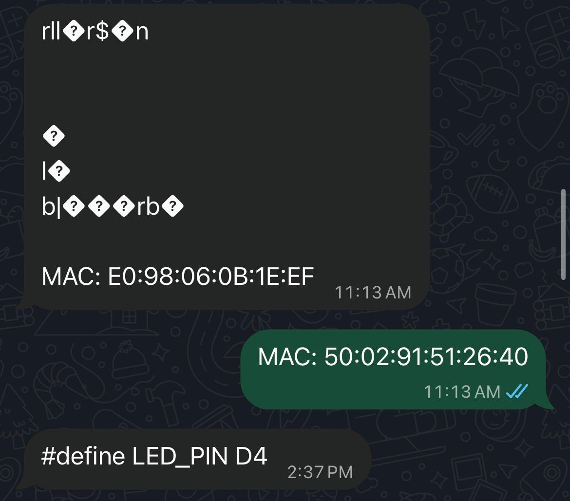
We ran it on both boards and swapped the results over chat. The scrambled characters at the top are normal: the ESP8266 prints boot messages at a different baud rate when it starts up, and the Serial Monitor shows them as junk.
| Node | MAC address | Sends to |
|---|---|---|
| Node A (my board) | 50:02:91:51:26:40 | Node B |
| Node B | E0:98:06:0B:1E:EF | Node A |
Each board's code gets the other board's MAC address as its peer. In my sketch that's Node B:
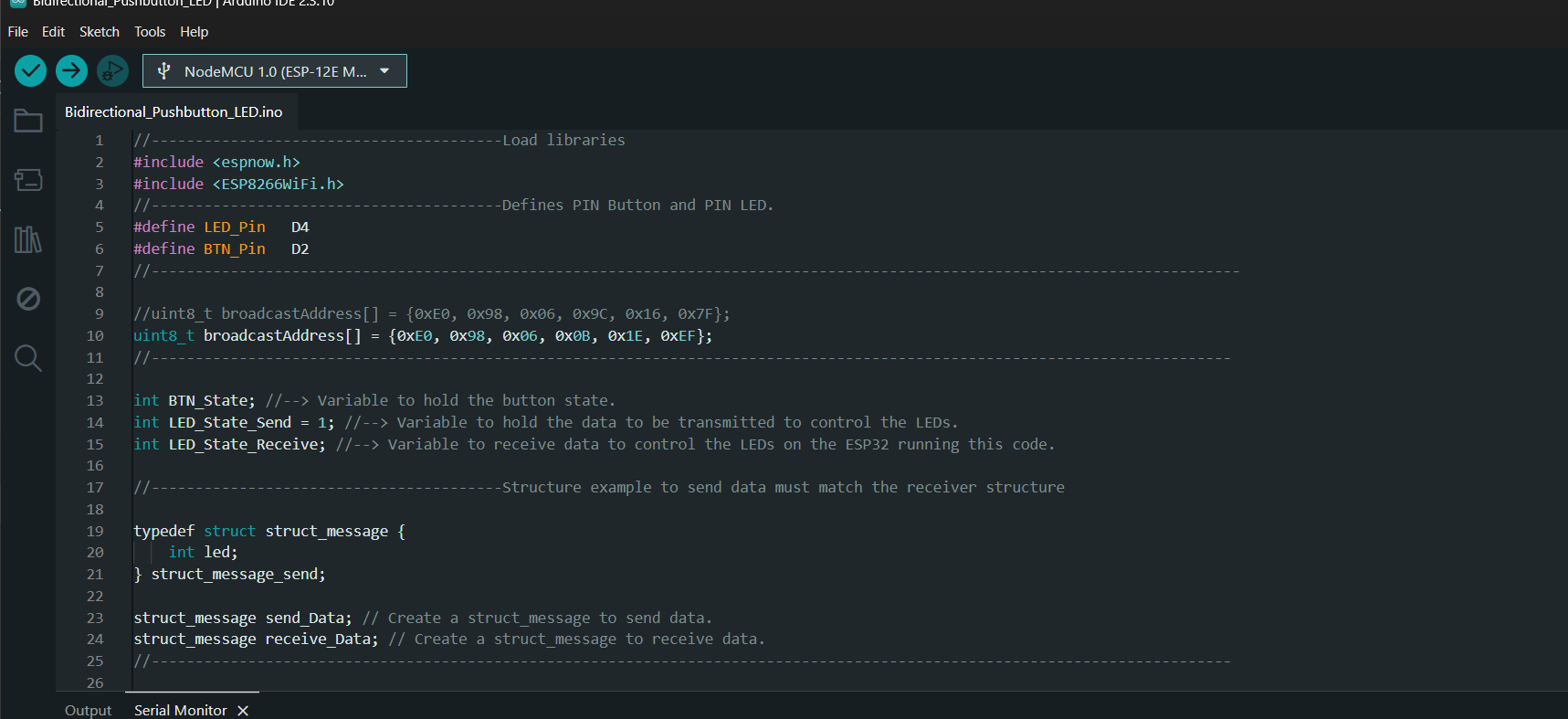
uint8_t broadcastAddress[] = {0xE0, 0x98, 0x06, 0x0B, 0x1E, 0xEF};
💻 The Code
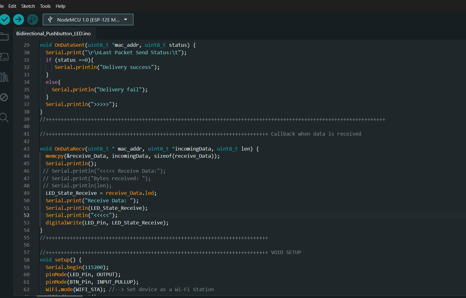
Both nodes run the same sketch, Bidirectional_Pushbutton_LED.ino, with the peer address swapped.
Each node is set to the COMBO role, which means it can both send and receive.
🔹 The message
The packet is tiny: a struct with a single integer, led, which is either 1 (on) or 0 (off).
Both boards must use the exact same struct, or the receiver reads the bytes wrong.
typedef struct struct_message {
    int led;
} struct_message_send;
🔹 Setup
- • Set the Wi-Fi mode to station (
WIFI_STA) and disconnect from any network - • Start ESP-NOW with
esp_now_init() - • Register two callbacks:
OnDataSent(did it arrive?) andOnDataRecv(something came in) - • Set the role to
ESP_NOW_ROLE_COMBOand add the other board as a peer
🔹 Sending (button pressed)
if(BTN_State == 0) {
  LED_State_Send = !LED_State_Send;   // toggle
  send_Data.led = LED_State_Send;
  esp_now_send(broadcastAddress, (uint8_t *) &send_Data, sizeof(send_Data));
  while(BTN_State == 0) {             // wait for release
    BTN_State = digitalRead(BTN_Pin);
    delay(10);
  }
}
The button uses INPUT_PULLUP, so it reads 0 when pressed. Each press flips the state and sends it.
The while loop waits until the button is released, so holding it down sends only one message.
🔹 Receiving
void OnDataRecv(uint8_t * mac_addr, uint8_t *incomingData, uint8_t len) {
  memcpy(&receive_Data, incomingData, sizeof(receive_Data));
  LED_State_Receive = receive_Data.led;
  digitalWrite(LED_Pin, LED_State_Receive);
}
When a packet arrives, the board copies the bytes into its struct and writes the value straight to the LED.
🔁 How a Message Travels
 NODE A  50:02:91:51:26:40                    NODE B  E0:98:06:0B:1E:EF
 ┌──────────────────────┐                     ┌──────────────────────┐
 │ button (D2) pressed  │                     │                      │
 │ led = !led  → 1      │                     │                      │
 │ esp_now_send(B, {1}) │ ─── ESP-NOW ──────▶ │ OnDataRecv()         │
 │                      │    {led: 1}         │ digitalWrite(D4, 1)  │
 │ OnDataSent():        │ ◀── ack ─────────── │ 💡 LED ON            │
 │ "Delivery success"   │                     │                      │
 └──────────────────────┘                     └──────────────────────┘

        ...and the same thing in reverse when Node B's button is pressed
| Serial Monitor message | Meaning |
|---|---|
Peer added successfully !! | The other board's MAC was registered |
>>>>> Send data | The button was pressed and a packet went out |
Delivery success | The other board confirmed it received the packet |
Delivery fail | No confirmation: wrong MAC, out of range, or the other board is off |
Receive Data: 1 | A packet arrived and the LED was set to that value |
🎬 It Works!
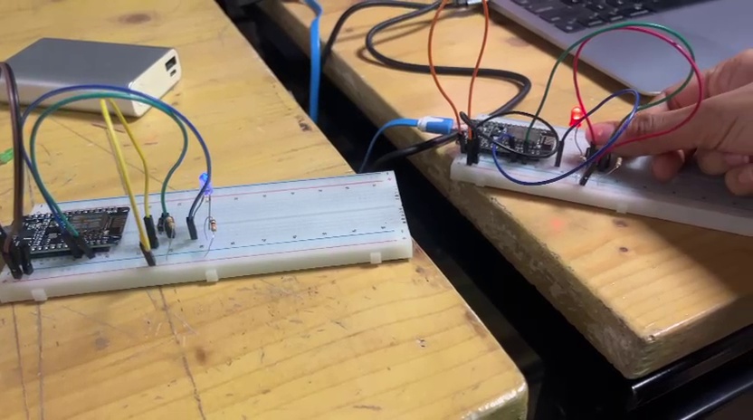
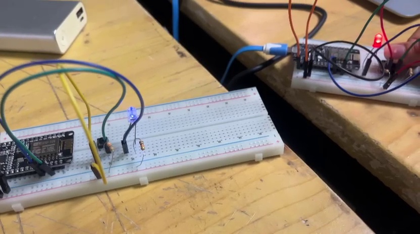
Here are the two nodes on separate breadboards, each powered on its own, with nothing connecting them. Pressing the button on one board switches the LED on the other.
⚠️ Things to Watch Out For
| Issue | Why it happens | What to do |
|---|---|---|
| Junk characters in the Serial Monitor on startup | The ESP8266 boot messages use a different baud rate | Ignore them; the real output starts after boot |
| Messages not arriving | The peer address has to be the other board's MAC, not your own | Print both MACs first, then swap them into each sketch |
| Mixing up pin names | D-labels on the board ≠ GPIO numbers | Use D2 / D4 in code, with the NodeMCU board selected |
| One press sending many messages | The loop reads the button many times while it's held | Wait for the button to be released before sending again |
✨ What I Learned
- • A network address can be as simple as a MAC address: every ESP board already has a unique one
- • ESP-NOW is great for small messages between boards without any router
- • Sender and receiver must agree on the exact message format (the struct)
- • Delivery callbacks are really useful for debugging: you know straight away if the other board heard you
- • Writing one sketch for both nodes, with only the address changing, keeps things simple
📁 Files
Bidirectional_Pushbutton_LED.inoGet_MacAddress.ino