Week 12 Machine Design
- Opening the Hoverboard
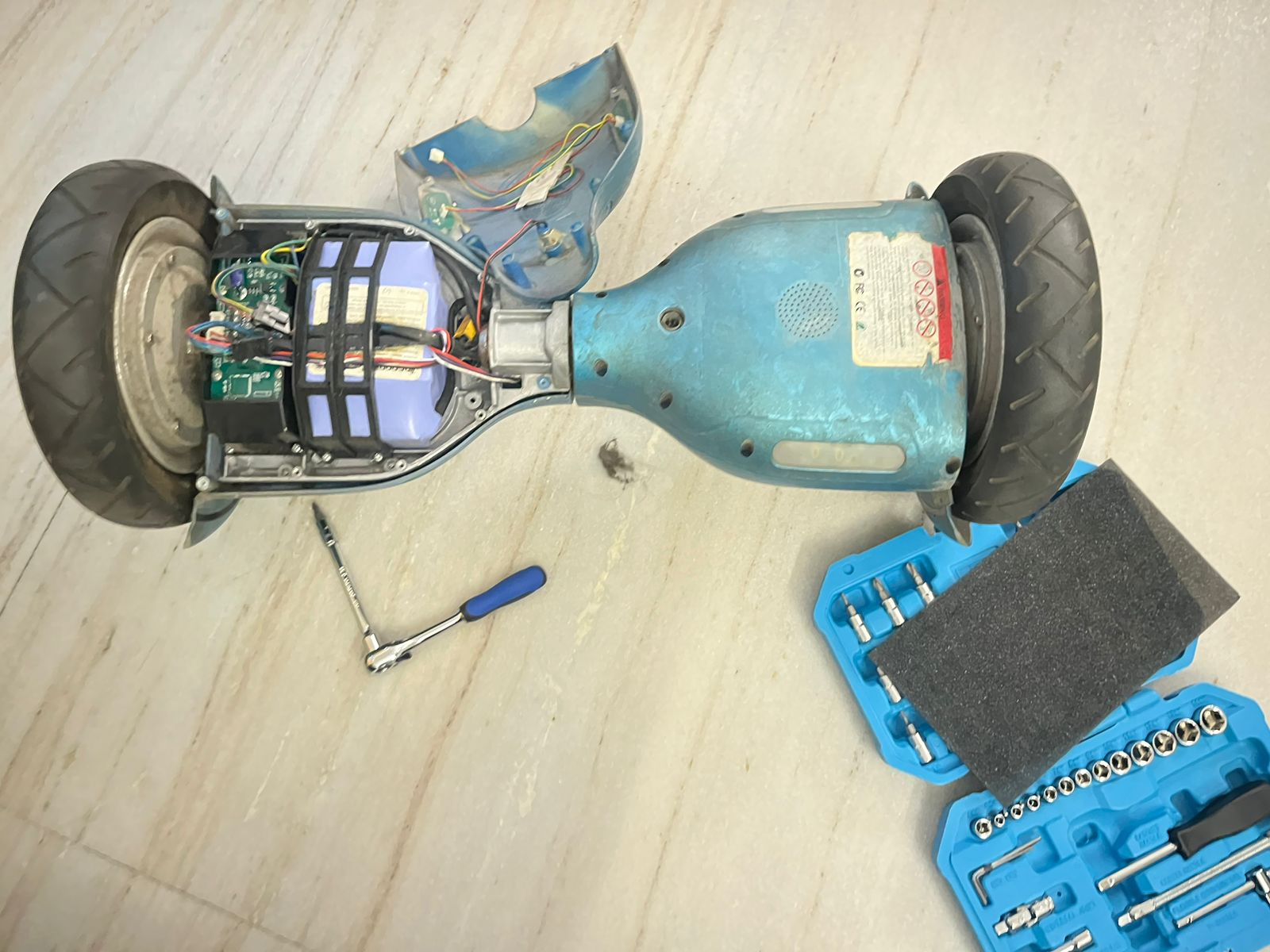
The process started by carefully opening the hoverboard using basic tools to access the internal components. Screws were removed and the outer casing was separated without damaging the wiring. This step helped expose the battery pack, control boards, and internal connections. Observing the layout gave a clear idea of how compactly everything is arranged. It also highlighted how both sides are symmetrically designed. This formed the base for further exploration and modification.
- Understanding Internal Electronics
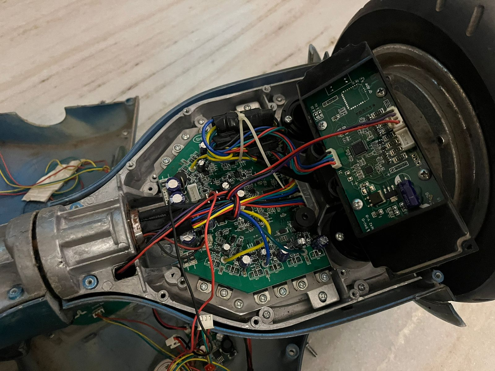
Once opened, the internal circuitry and wiring connections were closely examined. The main control board, connectors, and power distribution layout were identified. Each wire routing was studied to understand signal and power flow. Special attention was given to how the motor, battery, and sensors are interconnected. This step was crucial to avoid wrong disconnections later. It built a clear mental map of the system architecture.
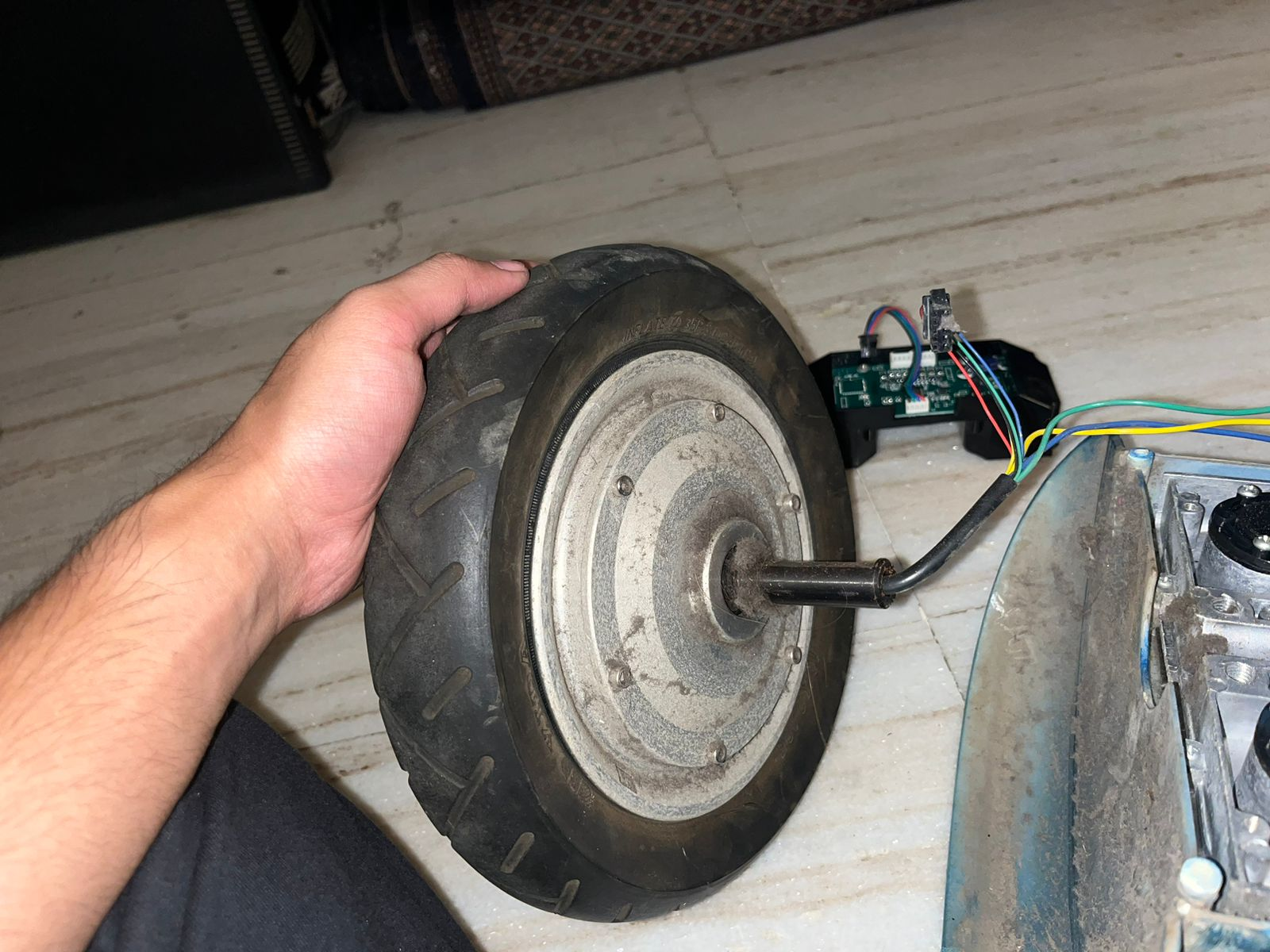
- Extracting the Hub Motor
The hub motor was carefully detached from the body since sourcing it separately was difficult. Mechanical fasteners and electrical connections were removed step by step. The motor structure, axle, and embedded wiring were examined. This gave insight into how compact and integrated the motor design is. Handling it separately made it easier to understand its working. This step was key for repurposing the motor in the new design.
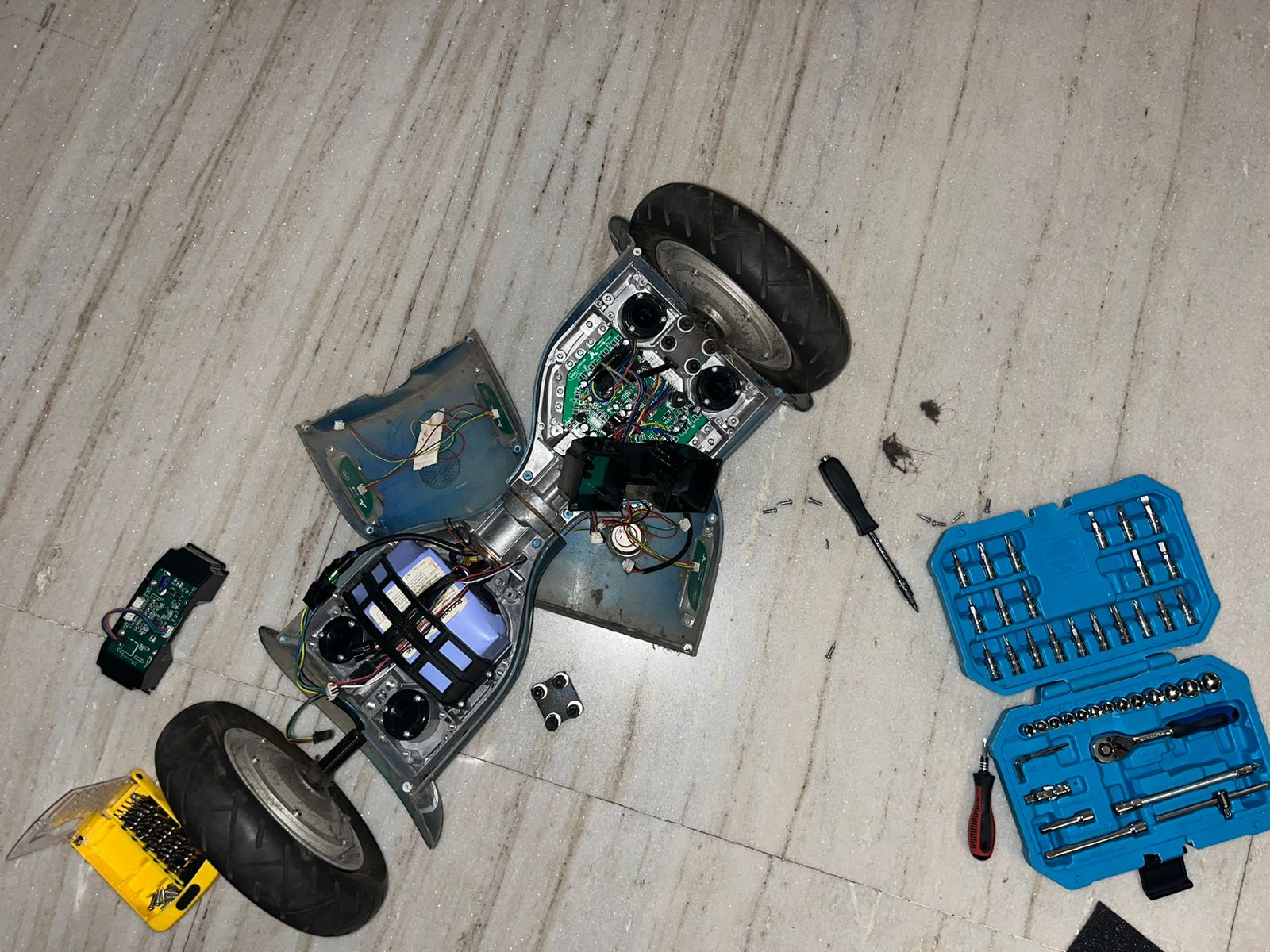
- Complete Disassembly
The entire hoverboard was dismantled to isolate all usable components. Both wheels, control boards, sensors, and casing parts were separated. This allowed a full inspection of each component individually. It also helped identify what can be reused and what can be discarded. The disassembly clarified the overall system construction. This stage ensured nothing critical was overlooked.
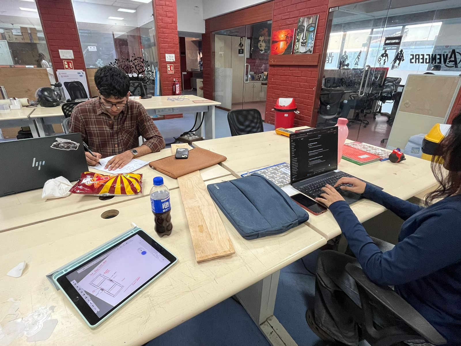
- Research and Planning
Parallel to the hardware teardown, research and planning were carried out. References were studied while sketching ideas and workflows. Discussions helped in deciding how to redesign the system into a single-wheel setup. This phase connected theoretical understanding with practical observations. It ensured that the next steps were not random but well thought out. Planning reduced trial-and-error during building.
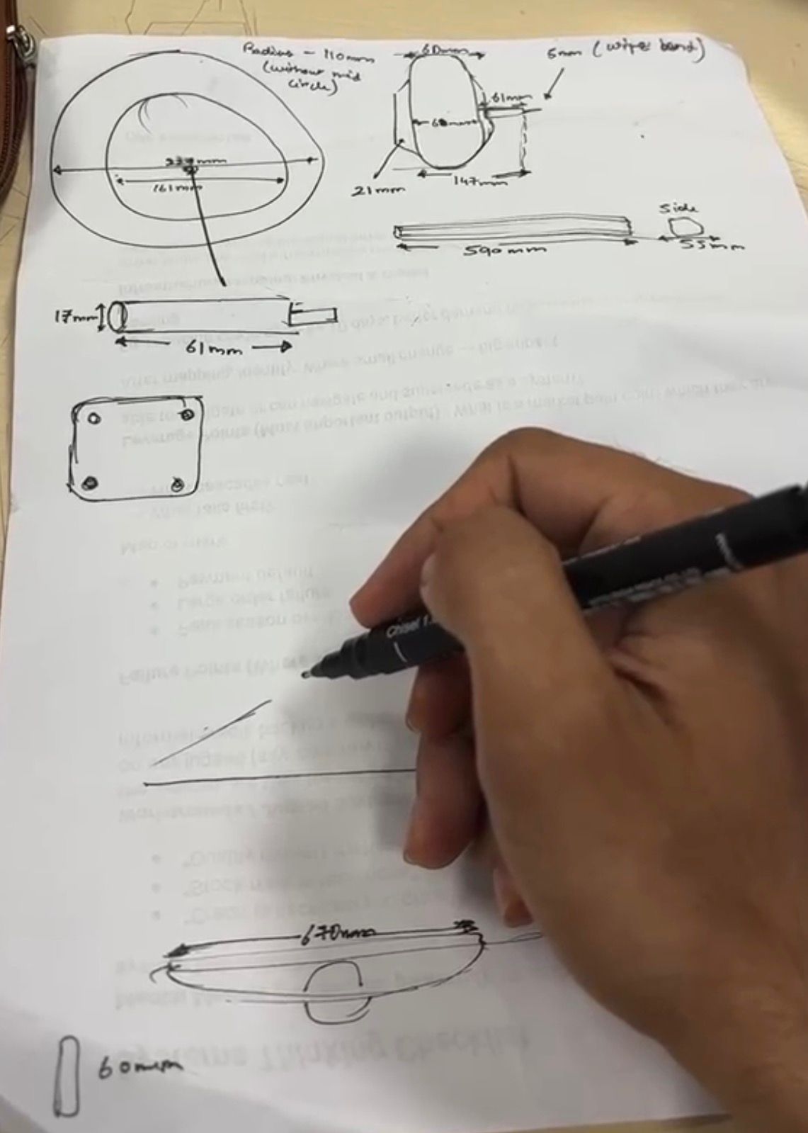
- Sketching and Dimensioning
Detailed sketches were made to define dimensions and component placement. Measurements of the footrest, motor space, and structural layout were noted. Different design options were explored on paper before fabrication. This step helped visualize proportions and ergonomics. It also ensured that all components would fit properly. Sketching acted as a bridge between idea and physical build.
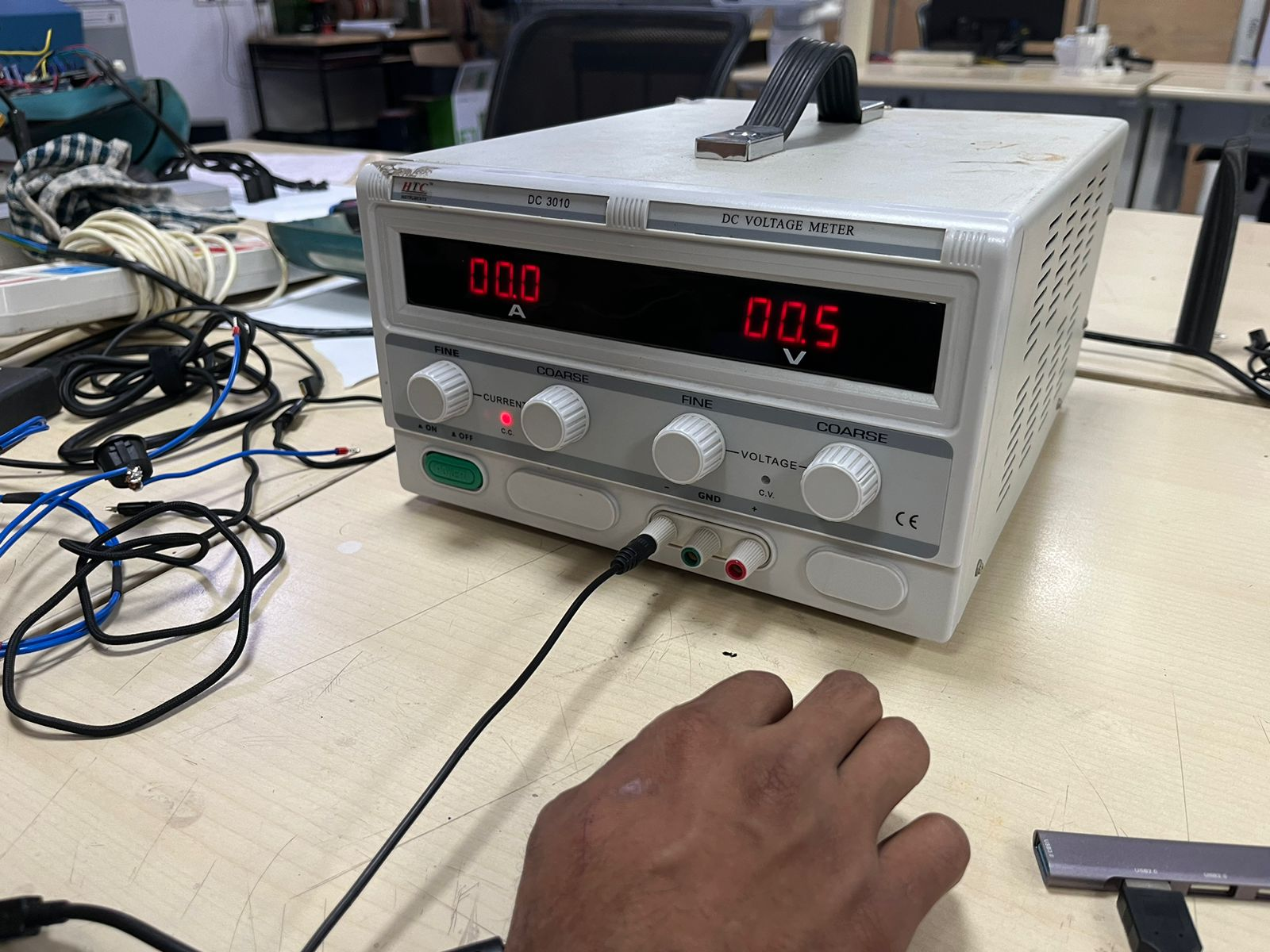
- Testing the Motor (Power Supply)
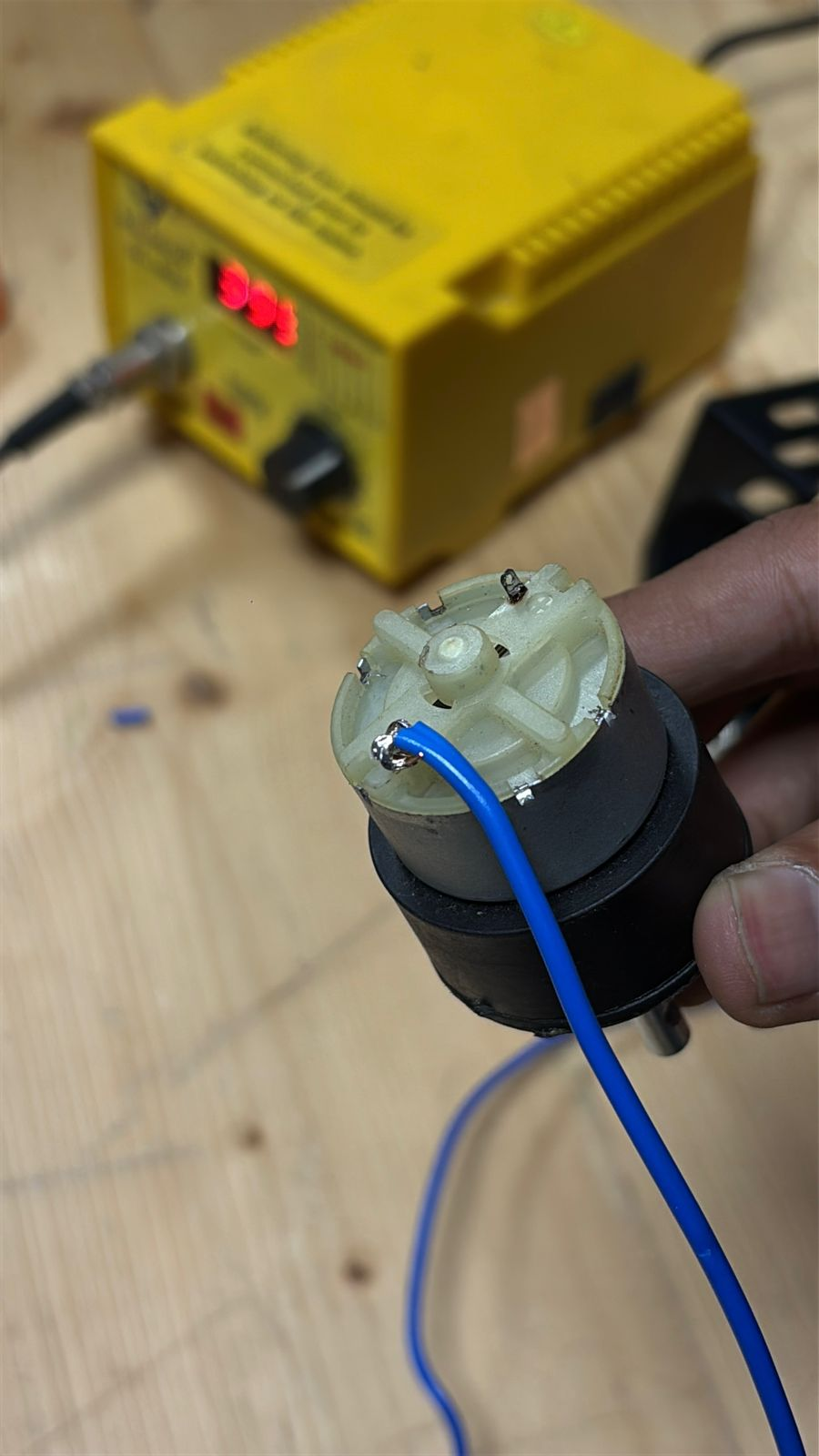
The extracted motor was tested using a DC power supply to understand its behavior. Voltage was gradually increased while observing response and rotation. This helped verify whether the motor was functioning properly. It also gave an idea of power requirements and control sensitivity. Testing reduced the risk of integrating a faulty component. This step validated the core driving element.
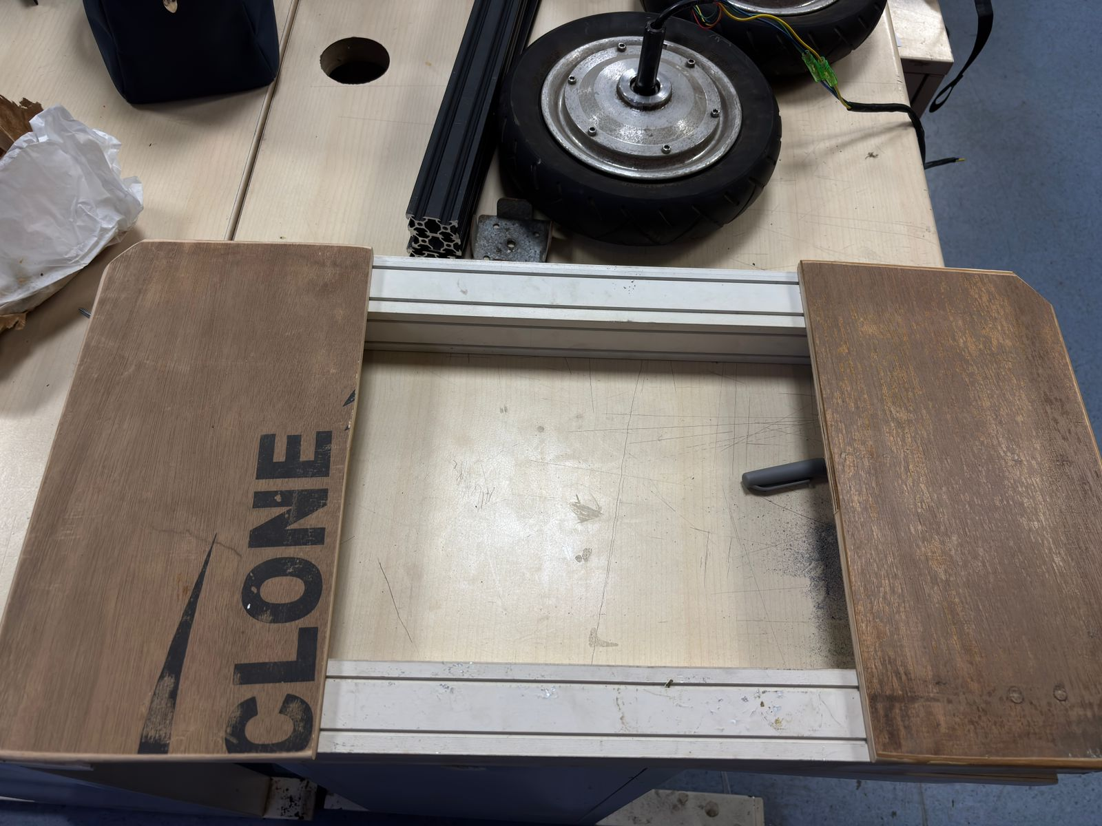
- Building the Structural Frame
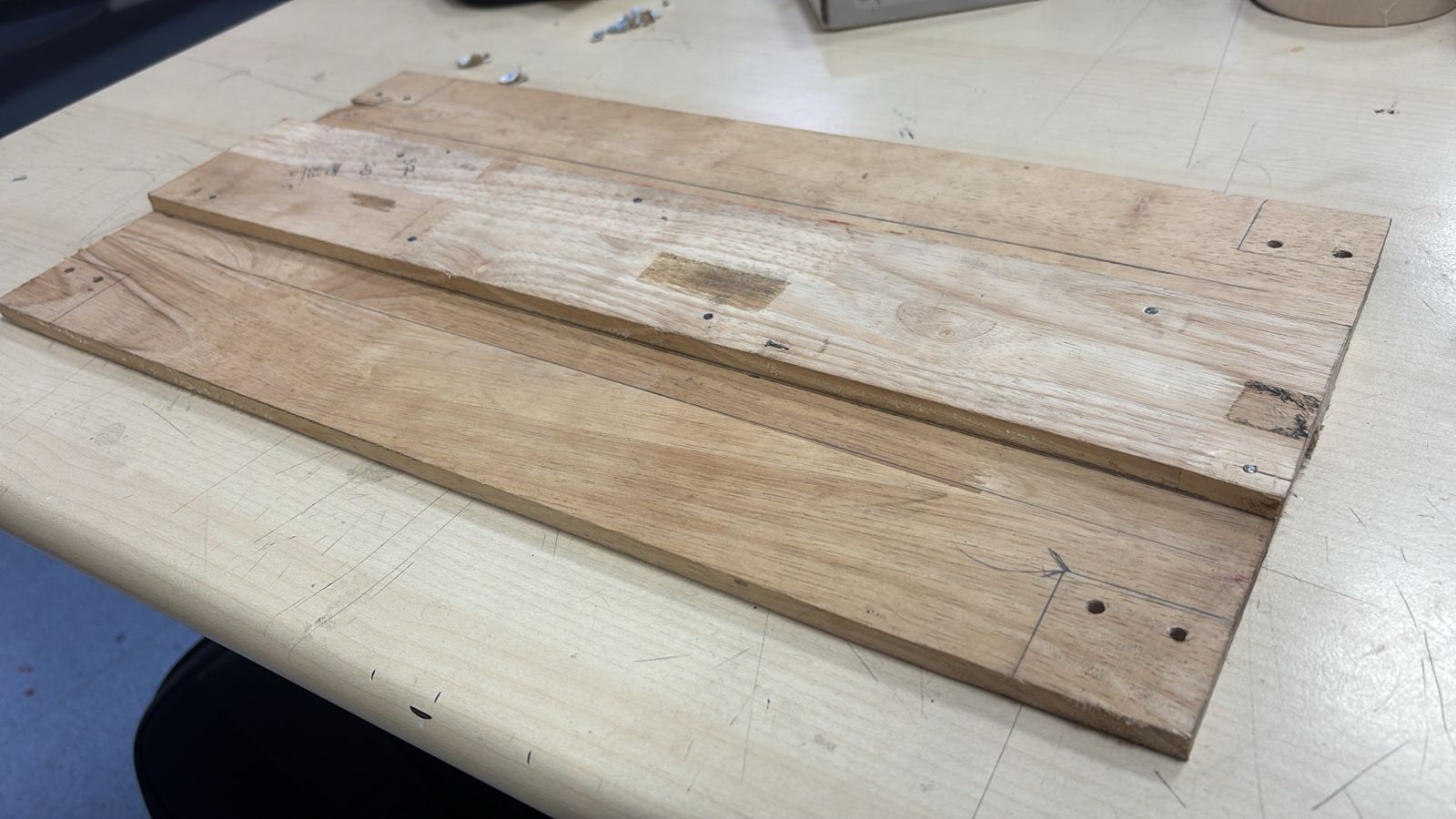
A basic structural frame was created using wooden panels and aluminum profiles. The design was based on earlier measurements and sketches. The frame defines the foot placement and motor positioning. Alignment and spacing were carefully maintained for stability. This stage transformed the concept into a physical form. It acted as the foundation for mounting all components.
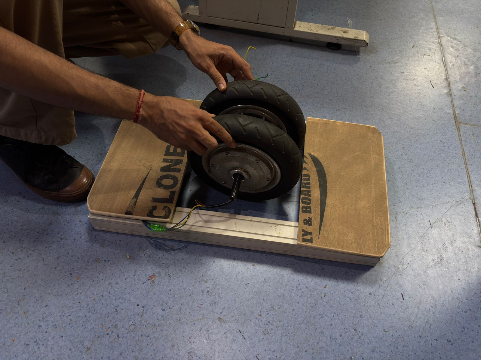
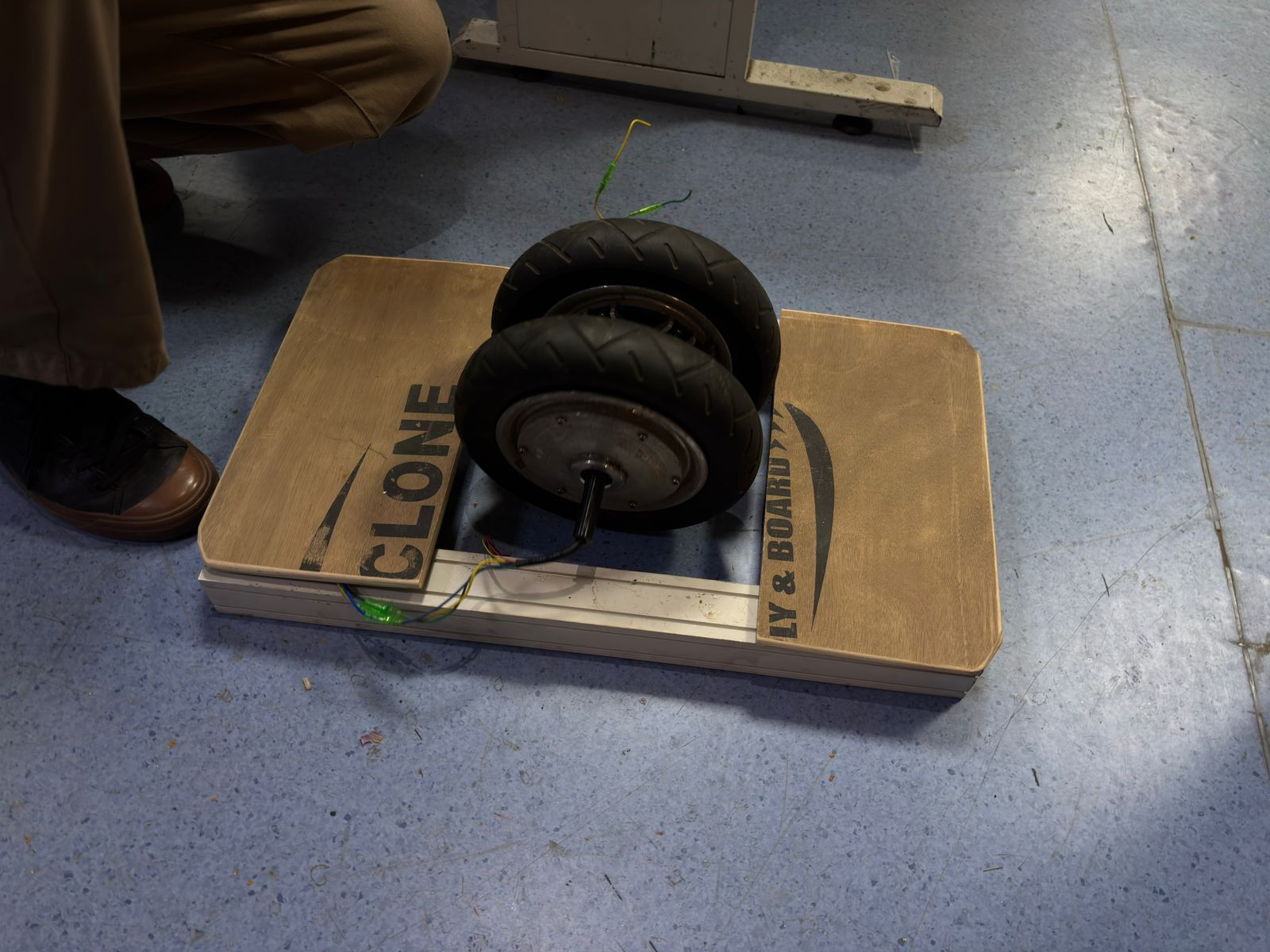
- Initial Assembly and Fit Check
The hub motor was placed into the newly built structure to check fit and alignment. Positioning was adjusted to ensure balance and usability. Wiring clearance and mounting feasibility were observed. This step helped identify practical issues in the design. Minor corrections could be made before final assembly. It confirmed that the design direction was workable.
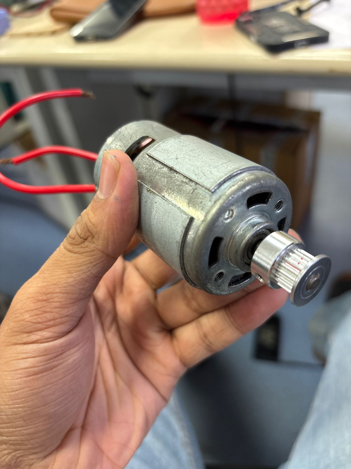
- DC Motor (Initial Attempt)
This is a standard DC motor that was initially considered for the setup. However, since most of the original hoverboard motors and sensors were tightly integrated with the master control board, it wasn’t feasible to reuse them directly. So an alternative motor was tested separately. While it worked electrically, it lacked the required torque to handle body weight. This made it unsuitable for load-bearing applications like the board. This step helped identify the limitations early.
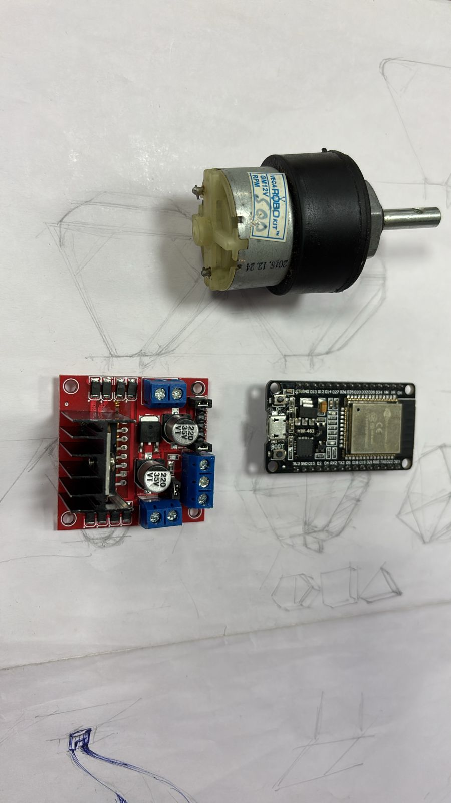
- Motor + Driver + ESP32 (Component Selection)
At this stage, the core components were finalized — a geared motor, L298N motor driver, and ESP32 WROOM dev kit. These were chosen to build an independent control system instead of relying on the original hoverboard electronics. The selection was based on availability, ease of control, and compatibility. This setup allows better flexibility in programming and testing. It marked the shift from reverse engineering to building a custom system.
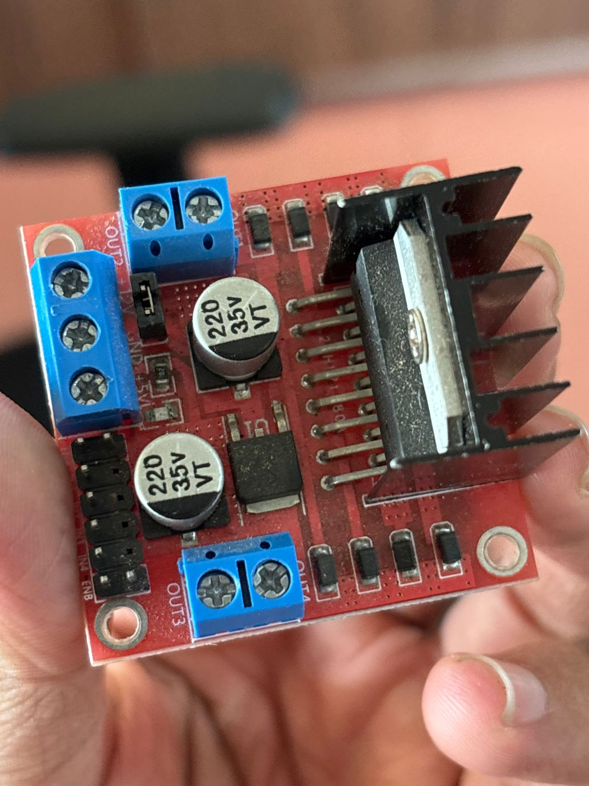
- L298N Motor Driver (Close-up)
The motor driver module was examined in detail to understand pin configuration and connections. Power inputs, motor outputs, and control pins were identified. Heat sink and current handling capability were also considered. This step ensured correct wiring with the ESP32 and motor. Understanding this module was critical for safe motor control. It acts as the bridge between logic signals and high-power motor operation.
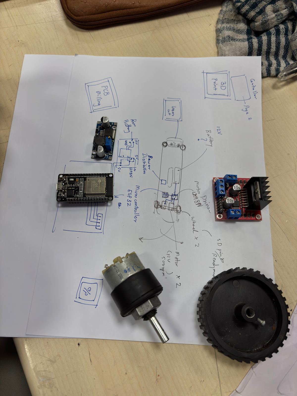
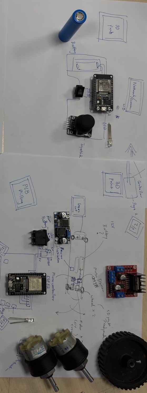
- System Layout Planning
All components were placed over a sketched layout to visualize connections and placement. Wiring paths, power distribution, and control flow were mapped out. This helped avoid confusion during actual assembly. The sketch also ensured that spacing and mounting positions were practical. It served as a blueprint before physical integration. This step reduced errors during wiring.
- Control Components Setup
The control side was explored using ESP32, joystick module, battery, and switches. This setup defines how the user will interact with the system. The joystick acts as the input interface for movement control. Power switching and LED indicators were also considered. This stage focused on interaction rather than mechanics. It ensured that the system is controllable and responsive.
- Component Arrangement Iteration
Multiple components including motors, drivers, and wheels were arranged together to validate system configuration. Different placement options were tested for balance and wiring convenience. This step helped refine the architecture of the system. It ensured that all components could coexist without interference. Iteration here avoided redesign later. It was a trial-fit stage before fixing anything permanently.
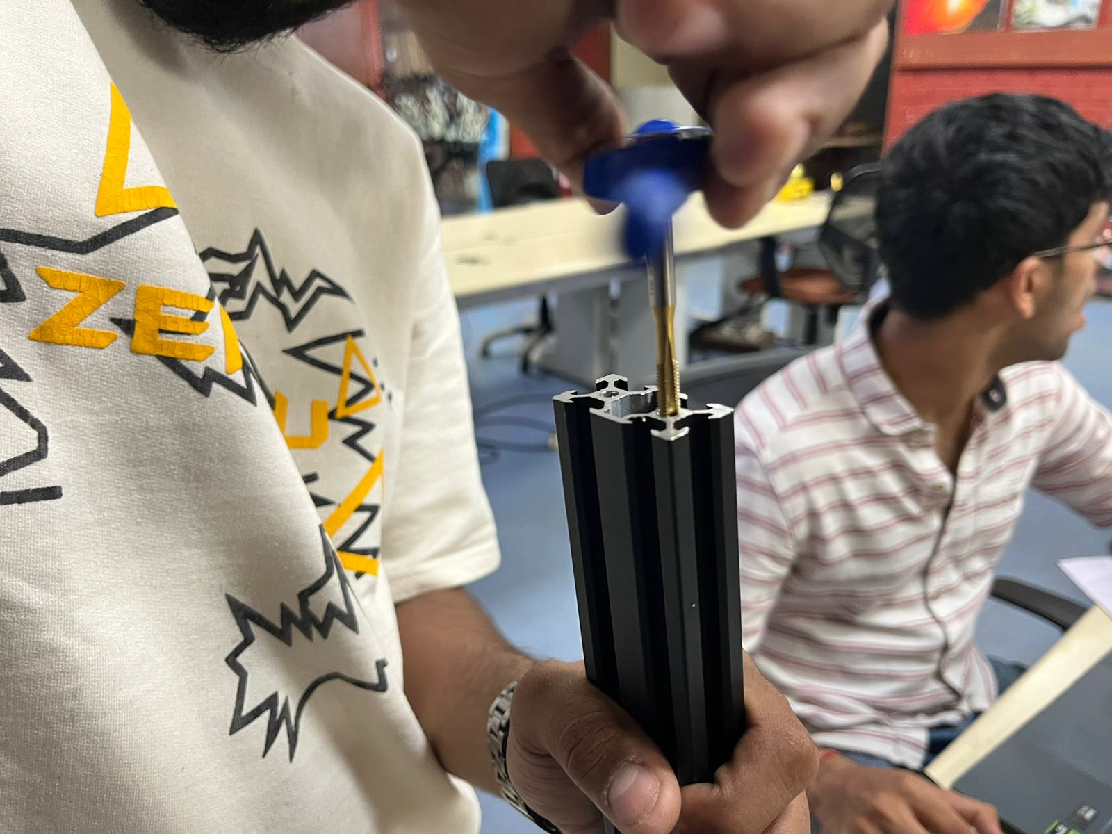
- Threading the Metal Frame The aluminum extrusion frame was prepared by adding threads using a tap tool. This allowed secure mounting of components using screws. Proper threading ensures structural strength and repeatability. It also makes the system modular and adjustable. This step converted raw material into a usable frame. It was essential for stable assembly.
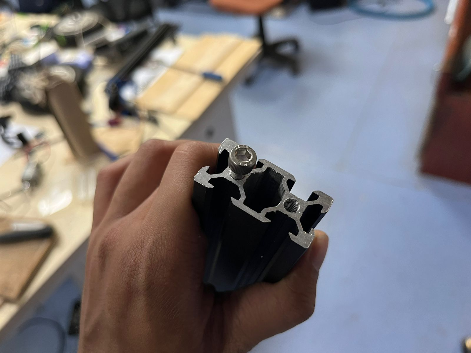
- Fastening and Mount Preparation After threading, screws and fasteners were tested within the frame slots. This ensured proper fit and alignment. The internal channel system of the extrusion was utilized effectively. Mounting points were finalized for different components. This step confirmed that the structure can hold mechanical loads. It prepared the frame for final assembly.
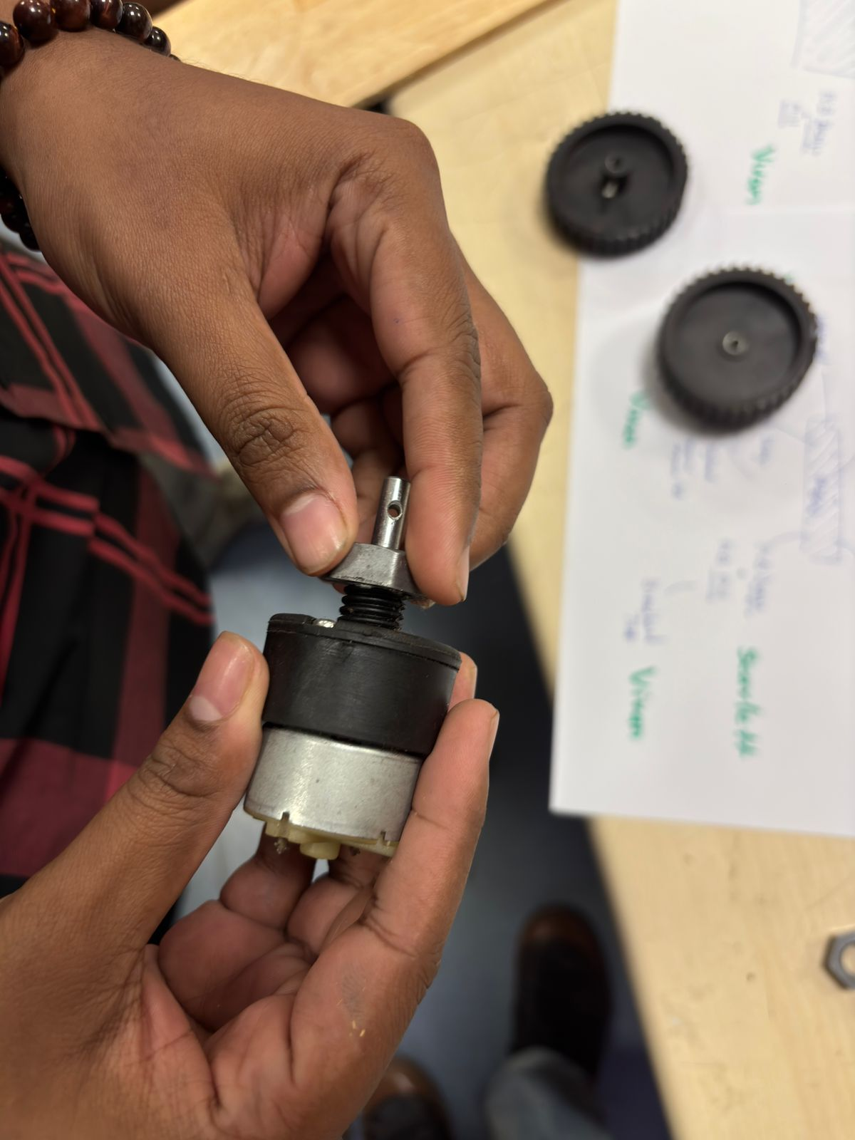
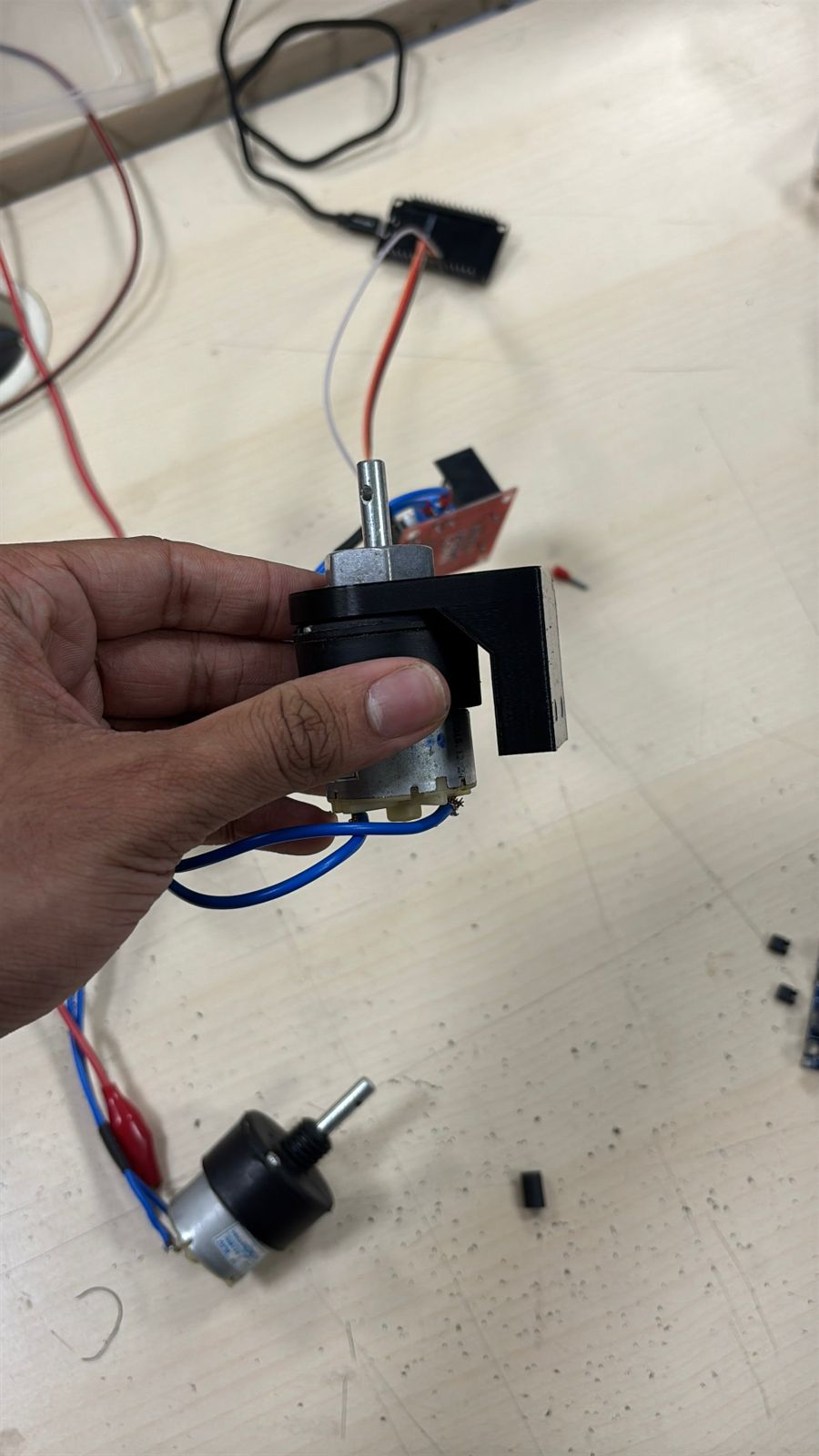
- Shaft Coupling and Motor Interface The motor shaft and coupling mechanism were examined to connect with the wheel. Proper alignment and fit were critical to avoid wobbling. This step ensured efficient transfer of rotational motion. Mechanical compatibility between motor and wheel was verified. Any mismatch here would cause instability. It was a key mechanical integration step.
1. We first desoldered the existing terminal points on the DC motor and removed the old connections. After that, we stripped a copper wire and soldered it directly onto the motor terminals to establish a fresh electrical connection. Care was taken to ensure proper wetting of solder so the joint is mechanically strong and electrically reliable.
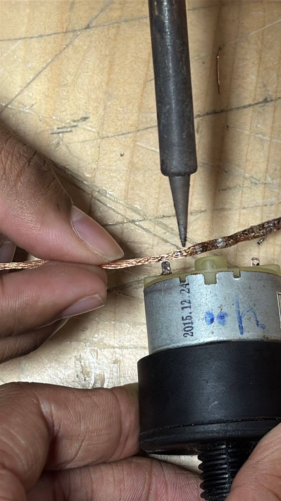
2. Once the wire was soldered, we checked the terminals and ensured there were no cold joints or loose connections. This step is important because poor soldering can cause intermittent motor behavior or voltage drops during operation.
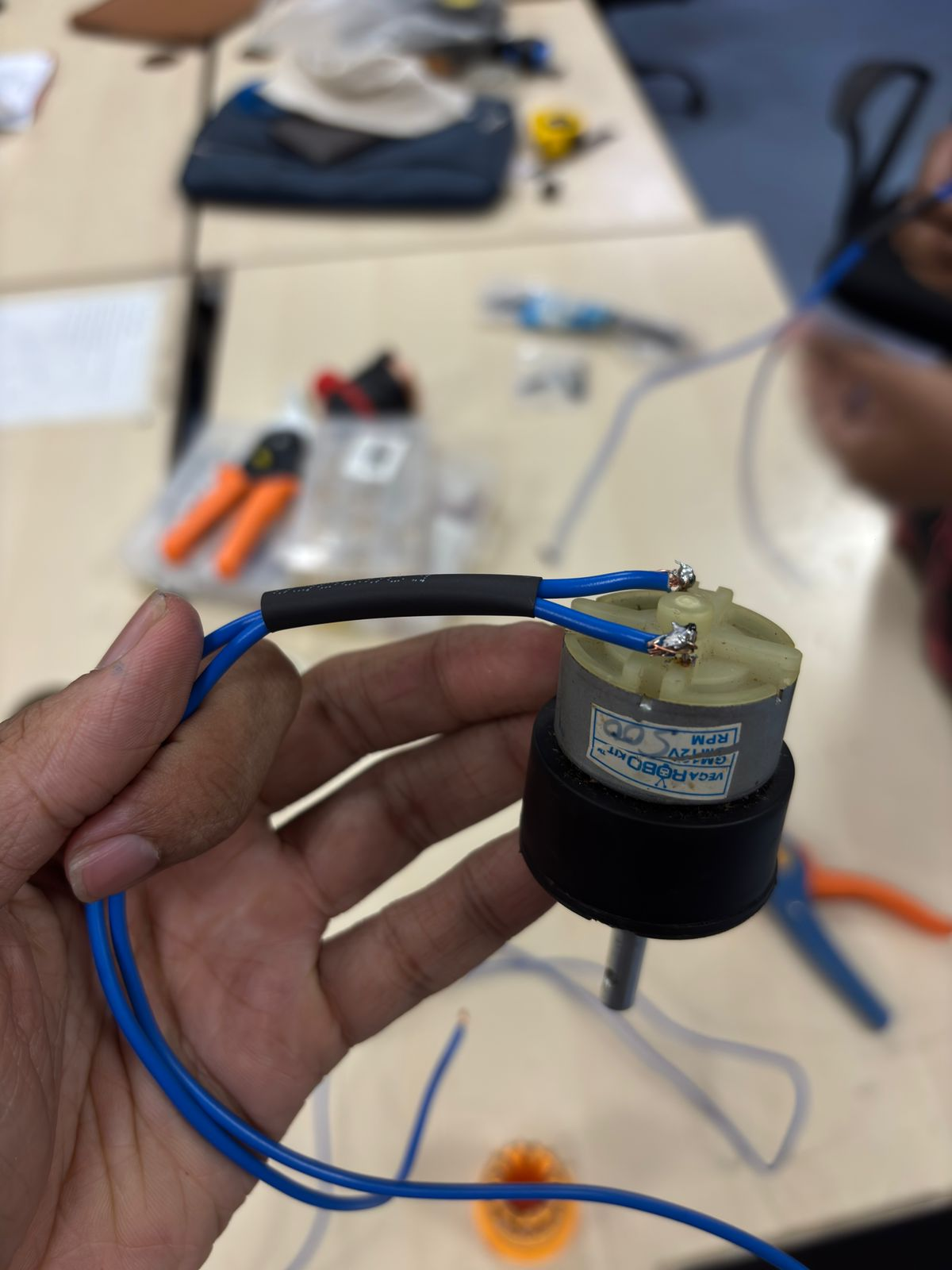
3. After confirming the connection, we applied a heat shrink tube (the black strip) over the joint. This provides electrical insulation, prevents short circuits, and also adds mechanical strain relief so the wire doesn’t break at the solder point.
 4.
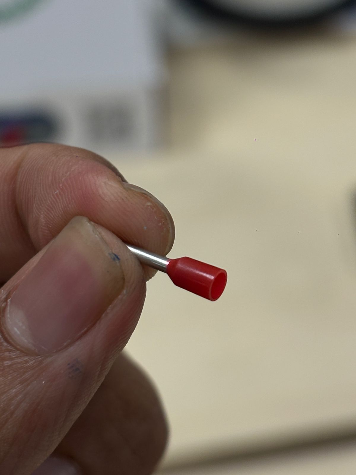
We then explored different wire end connectors and selected bootlace ferrules (wire end ferrules). These are used to neatly terminate stranded wires, making them suitable for insertion into screw terminals without fraying.
4.
We then explored different wire end connectors and selected bootlace ferrules (wire end ferrules). These are used to neatly terminate stranded wires, making them suitable for insertion into screw terminals without fraying.
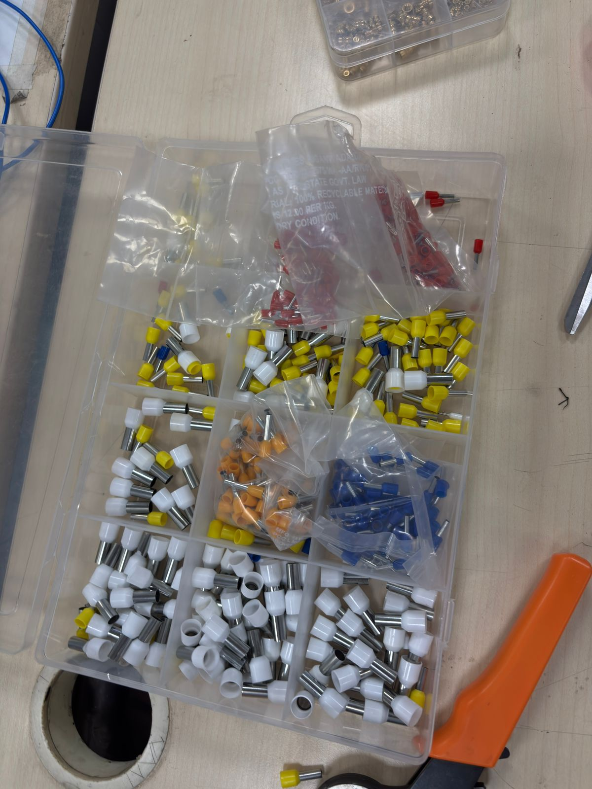
5. A ferrule was inserted onto the stripped wire end, ensuring all copper strands were inside. This improves conductivity and ensures a firm and clean connection.
 6.
Using a crimping tool, we crimped the ferrule onto the wire. Crimping compresses the metal sleeve tightly around the strands, creating a low-resistance and vibration-resistant connection.
6.
Using a crimping tool, we crimped the ferrule onto the wire. Crimping compresses the metal sleeve tightly around the strands, creating a low-resistance and vibration-resistant connection.
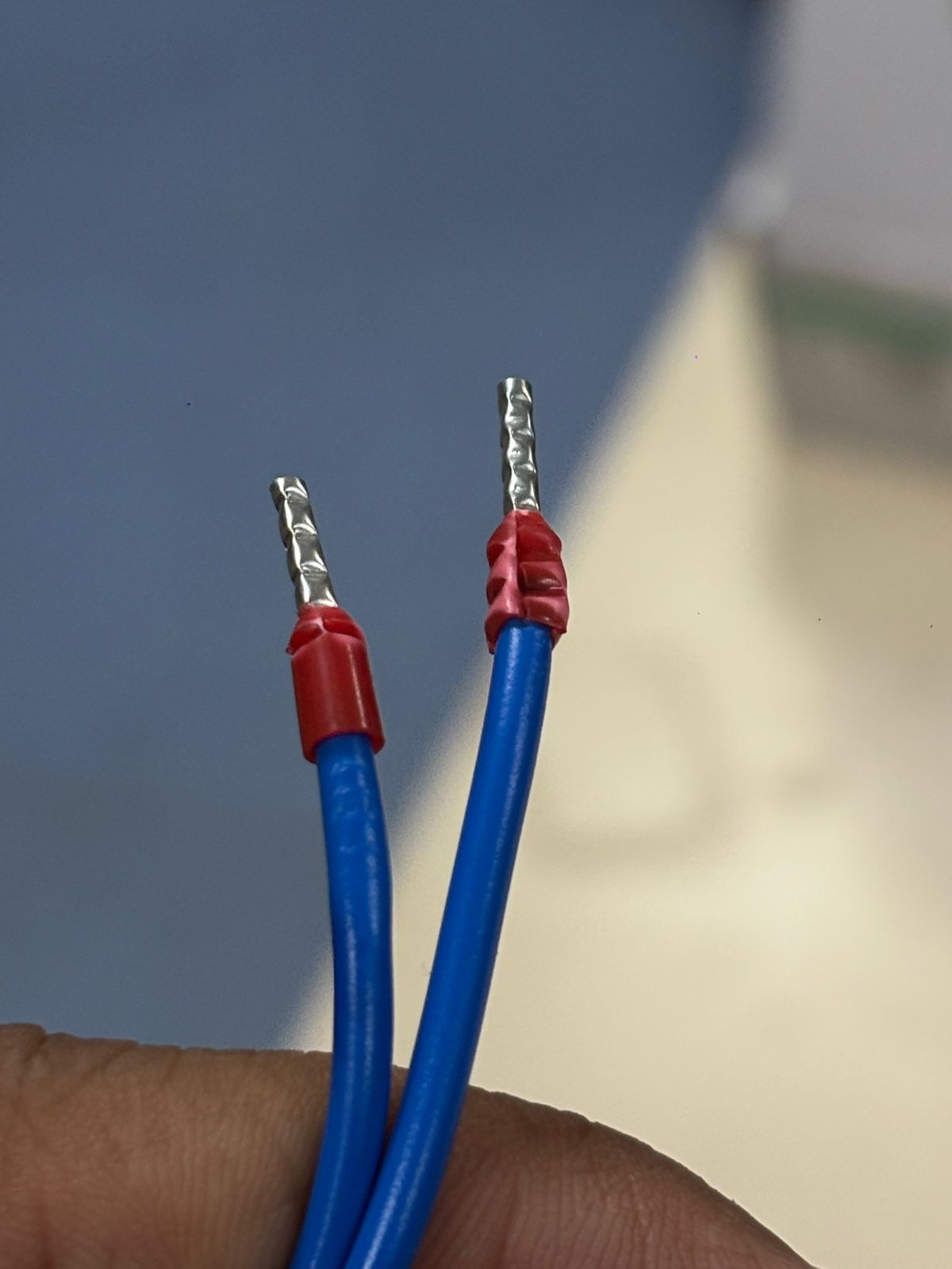 7.
Both wires were prepared similarly with ferrules, ensuring uniform and professional wiring. This step is especially important when connecting to motor drivers or terminal blocks.
7.
Both wires were prepared similarly with ferrules, ensuring uniform and professional wiring. This step is especially important when connecting to motor drivers or terminal blocks.
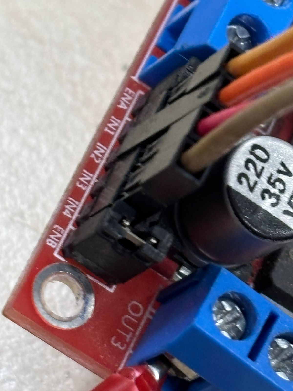
8. We then connected the wires to the motor driver module (L298N). Only the four middle pins (IN1, IN2, IN3, IN4) were used for control. The outer pins (ENA, ENB) were not used because we were not implementing speed control using PWM at this stage.
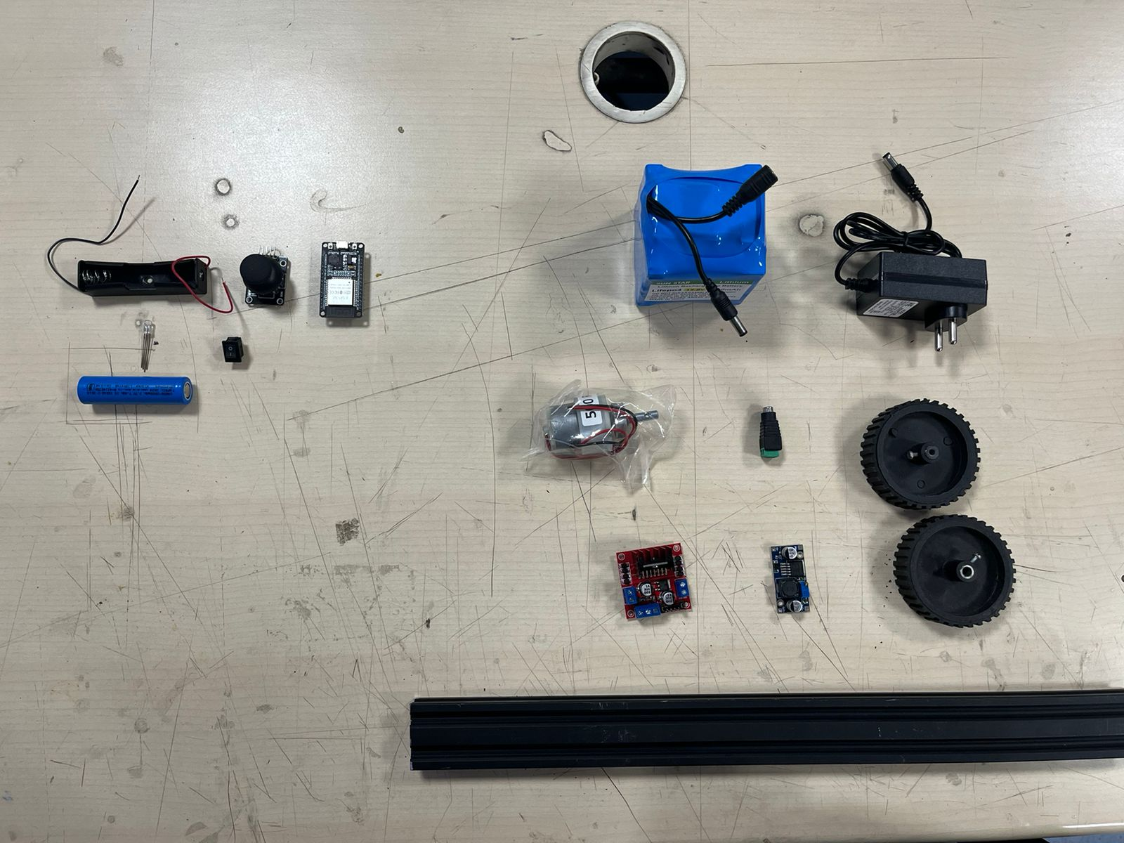
- Component Inventory All required components were laid out systematically including battery, motors, drivers, wheels, and frame parts. This helped ensure nothing was missing before assembly. It also gave a clear overview of the system scale. Organizing components improved workflow efficiency. This step acted like a checklist before building. It reduced interruptions during assembly.
Separate Section – Wooden Structure Optimization Initially, a heavier wooden base was used, but it restricted wheel movement due to excess load. This made the system inefficient and hard to drive. To solve this, the wooden structure was redesigned and reduced in weight. Material was optimized while maintaining strength. This significantly improved motor performance. It highlights the importance of weight balance in mobility systems.
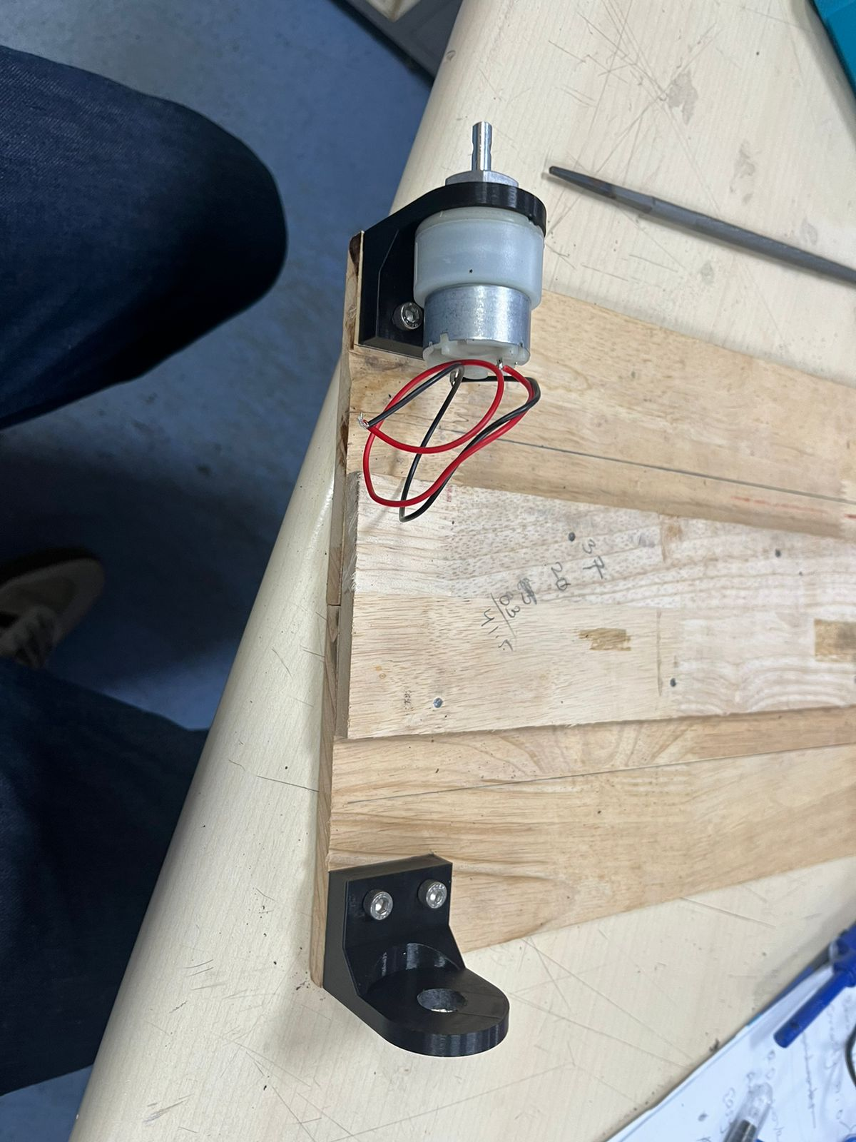
- Motor Mounting on Frame The motor was mounted onto the wooden base using a custom bracket. Alignment was carefully maintained to ensure proper rotation. The mounting ensured that the motor stays rigid under load. This step connected mechanical design with real hardware. It was crucial for stability during operation. The base structure started taking functional shape here.
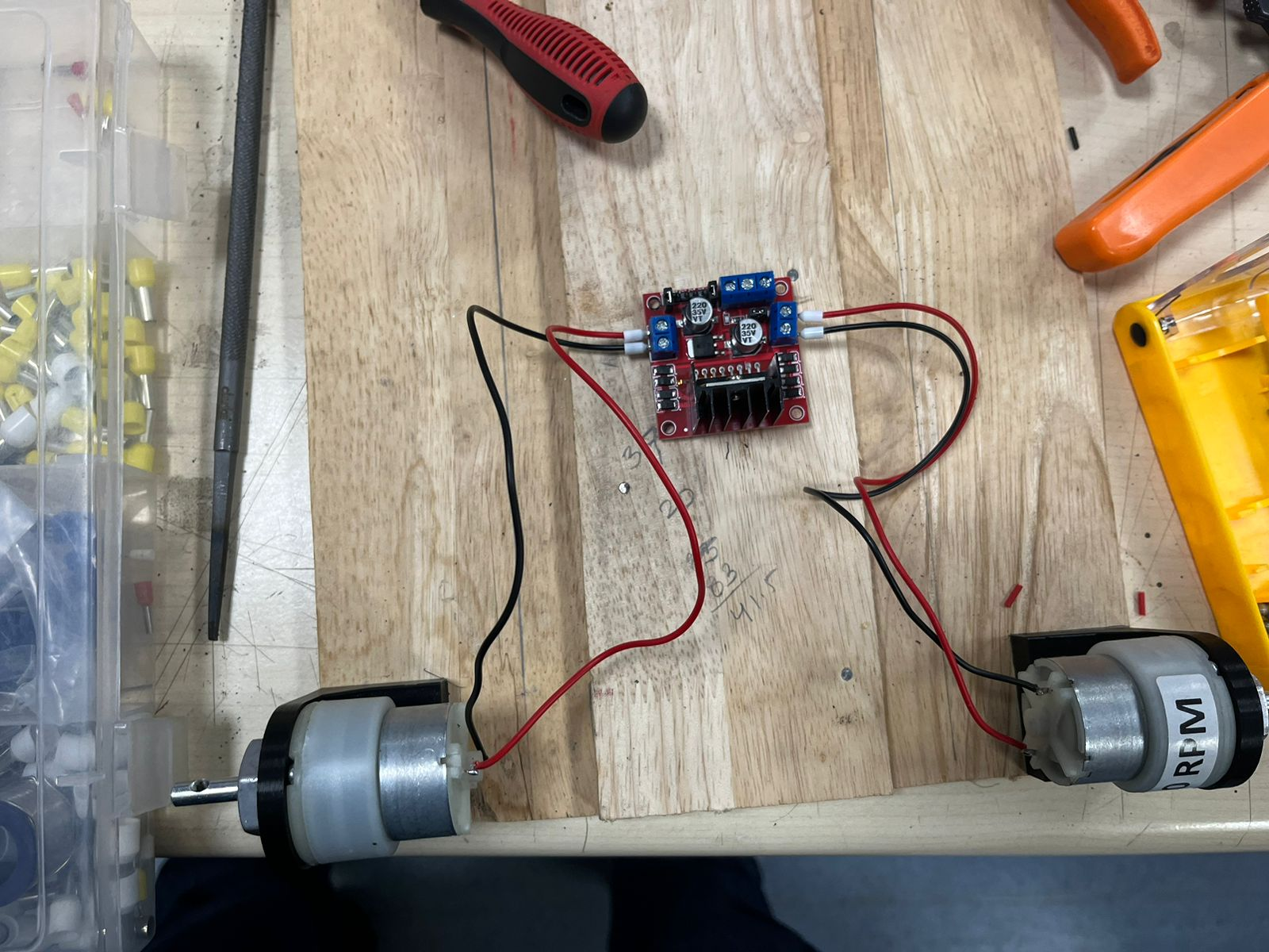
- Motor Driver Wiring Both motors were connected to the L298N driver to test simultaneous operation. Proper polarity and connections were verified. This setup demonstrated how motors will be controlled via the driver. It also helped test direction control and response. Early testing reduced chances of wiring errors later. This was the first functional electronics integration.
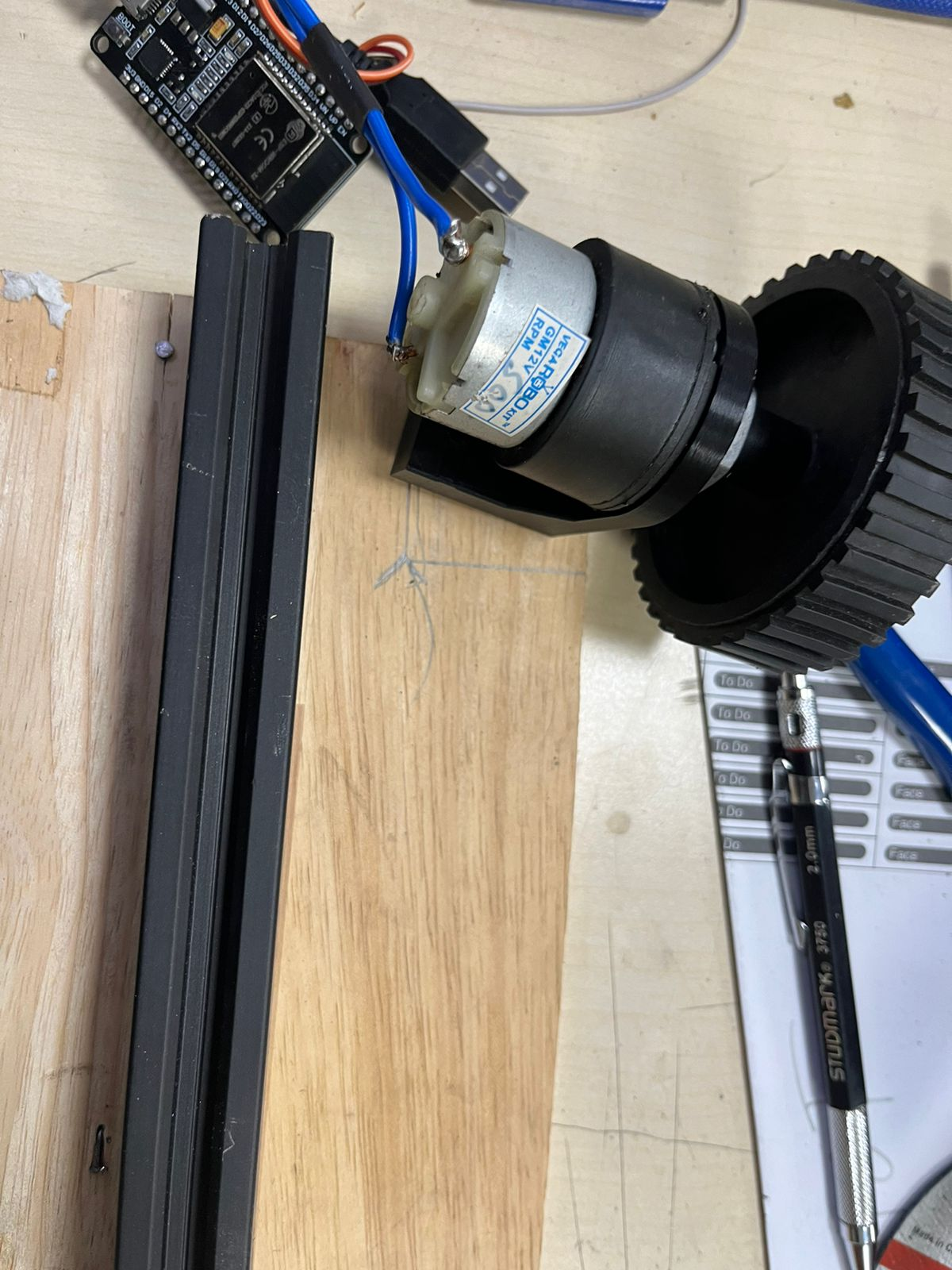
- Final Motor + Wheel Integration The motor was integrated with the wheel and mounted onto the frame. The ESP32 was connected for control signals. This marked the transition from isolated components to a working system. Mechanical and electronic systems were now combined. Alignment, wiring, and control were tested together. This step brought the prototype close to functional testing.
We mounted the motor securely using a custom L-bracket, ensuring proper shaft alignment for wheel attachment. This improves mechanical stability and reduces vibration during operation.
Both motors were wired to the motor driver and ESP32, completing the basic drivetrain setup. Power and signal lines were organized to avoid loose connections and interference.
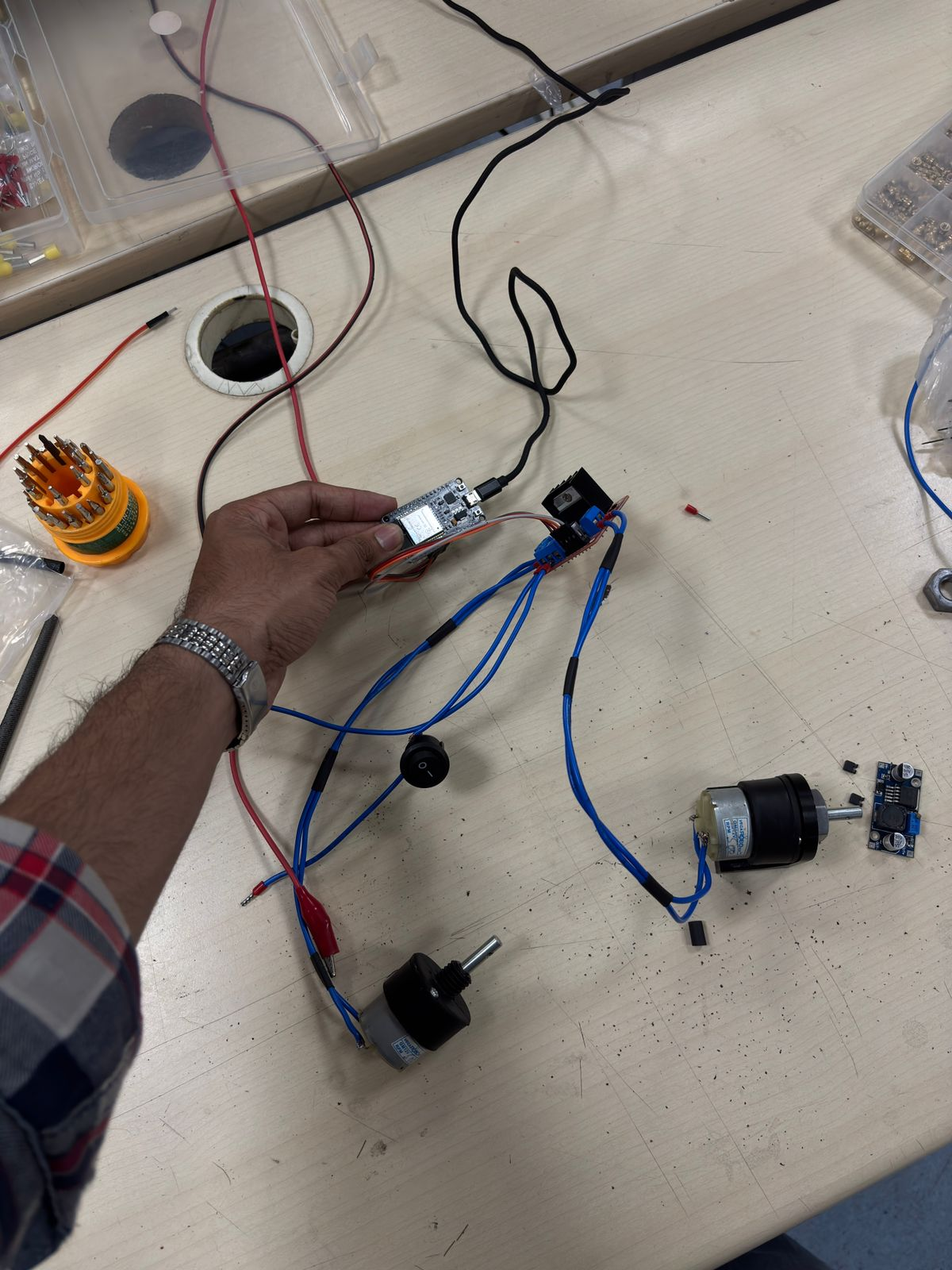
The ESP32 was connected via header pins and jumper wires to the motor driver module. Each control pin (IN1–IN4) was mapped to GPIO pins to control motor direction programmatically.The full system was tested using a regulated DC power supply. Voltage (~12V) was provided to the motor driver, while the ESP32 handled logic control. This step verified motor response and wiring correctness.
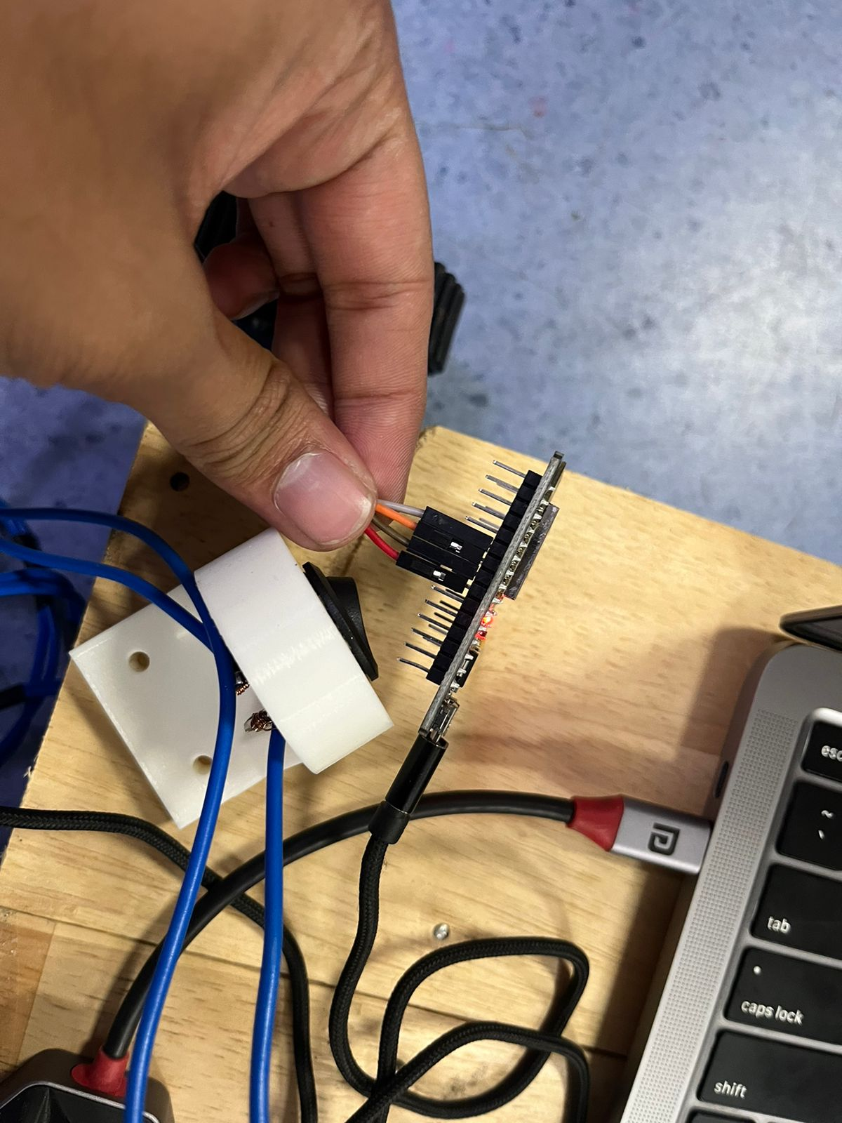
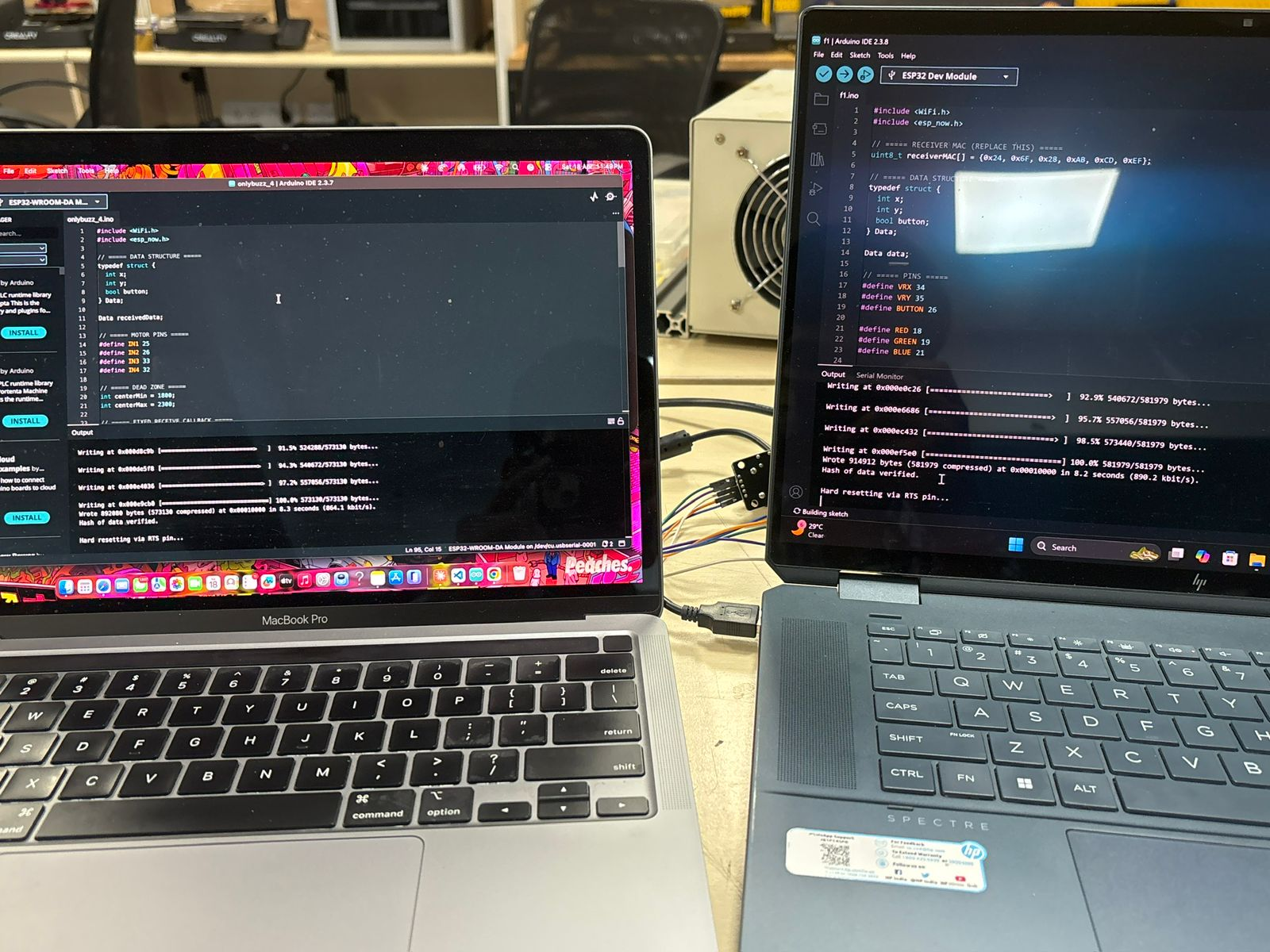
Two ESP32 boards were programmed—one as a transmitter (remote) and the other as a receiver (robot). Communication was established using ESP-NOW protocol, a peer-to-peer wireless system that works without Wi-Fi routers.
The transmitter reads joystick/button inputs Packs data (e.g., forward, backward, left, right) into a structure Sends it using MAC address of the receiver The receiver decodes it and triggers motor control accordingly
This allows real-time low-latency control.
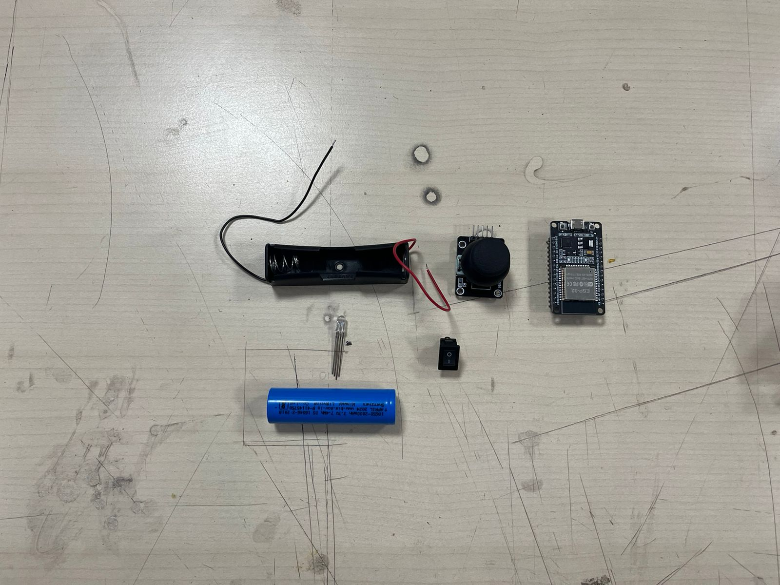
All components required for the controller were arranged: battery holder, joystick module, ESP32, switch, and indicator LEDs. LEDs were assigned to indicate movement directions (forward, backward, left, right).
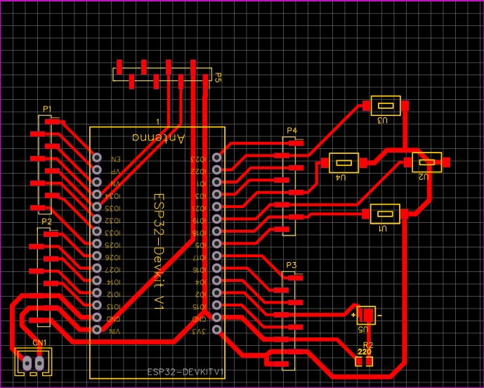
The controller circuit was designed in EasyEDA, including proper routing of signal lines, power traces, and LED indicators. This ensured a compact and reliable custom PCB design.
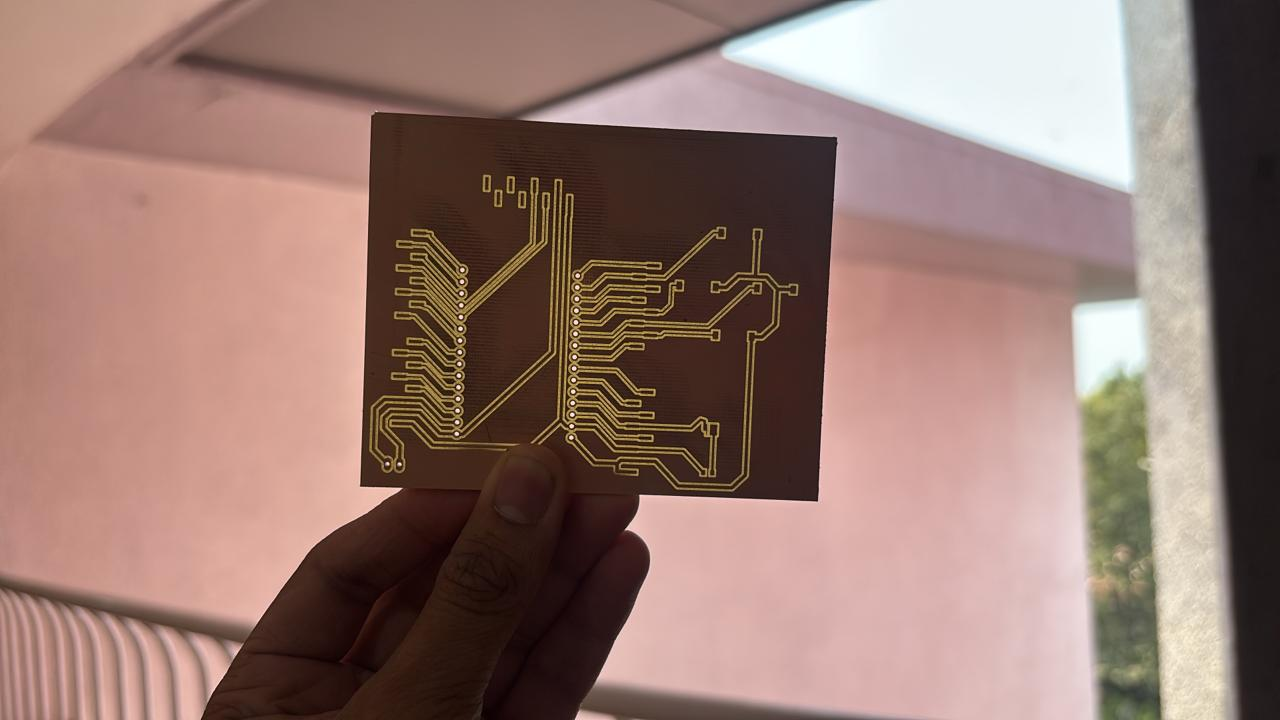
The PCB was then milled, producing a physical board from the design file. This replaced loose wiring with a cleaner and more robust circuit layout.
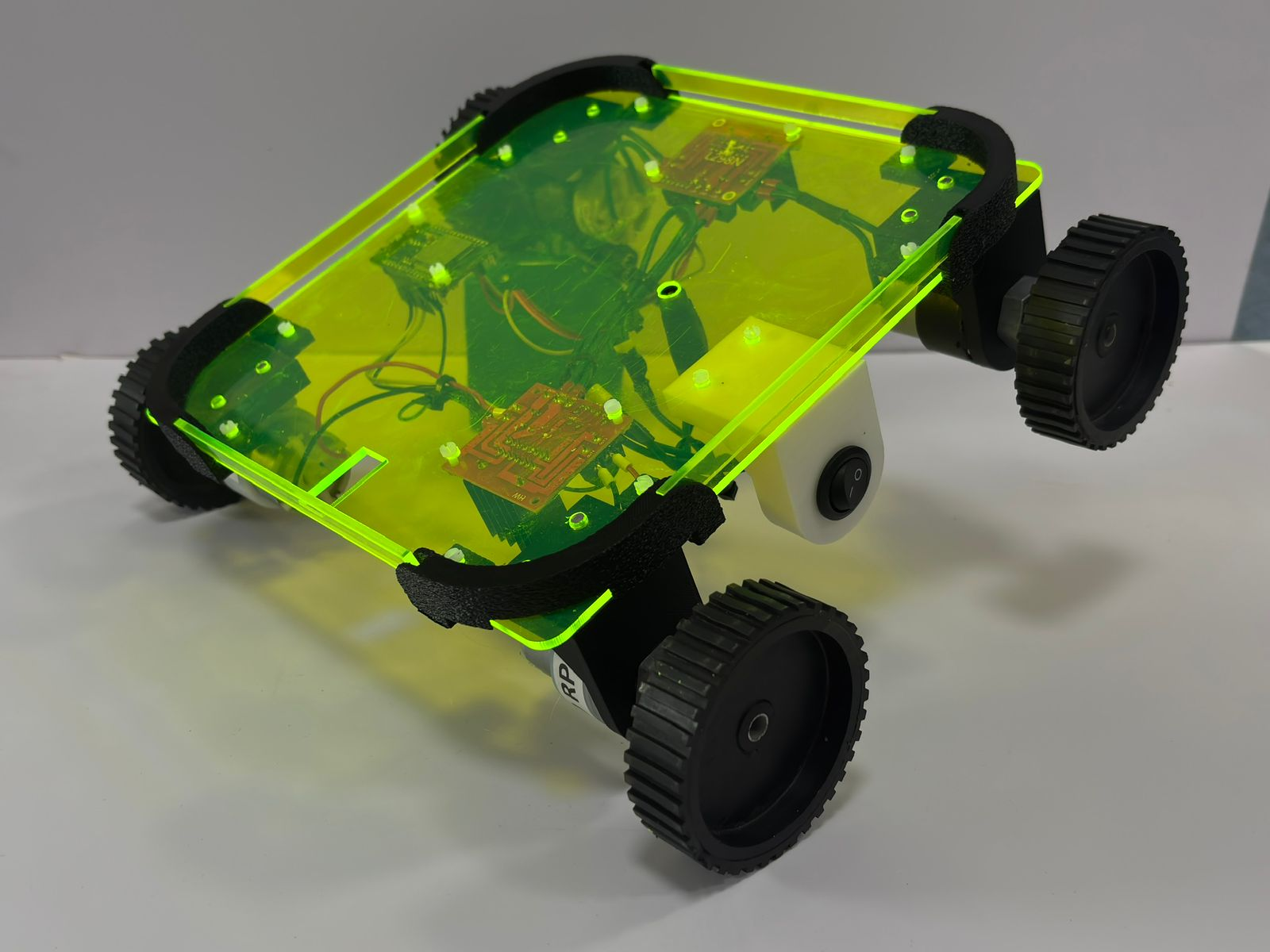
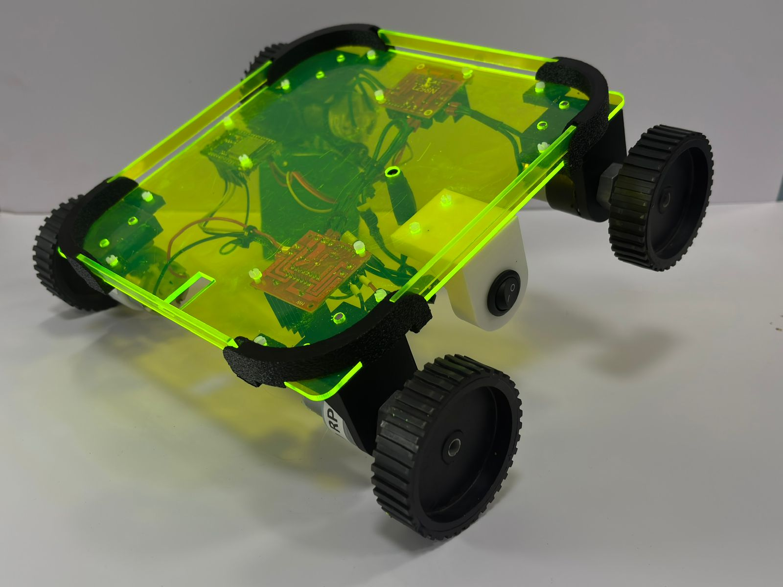
Initially, the base was made of wood, but due to excess weight affecting motor efficiency and battery load, it was replaced with an acrylic sheet, significantly reducing overall mass and improving movement.
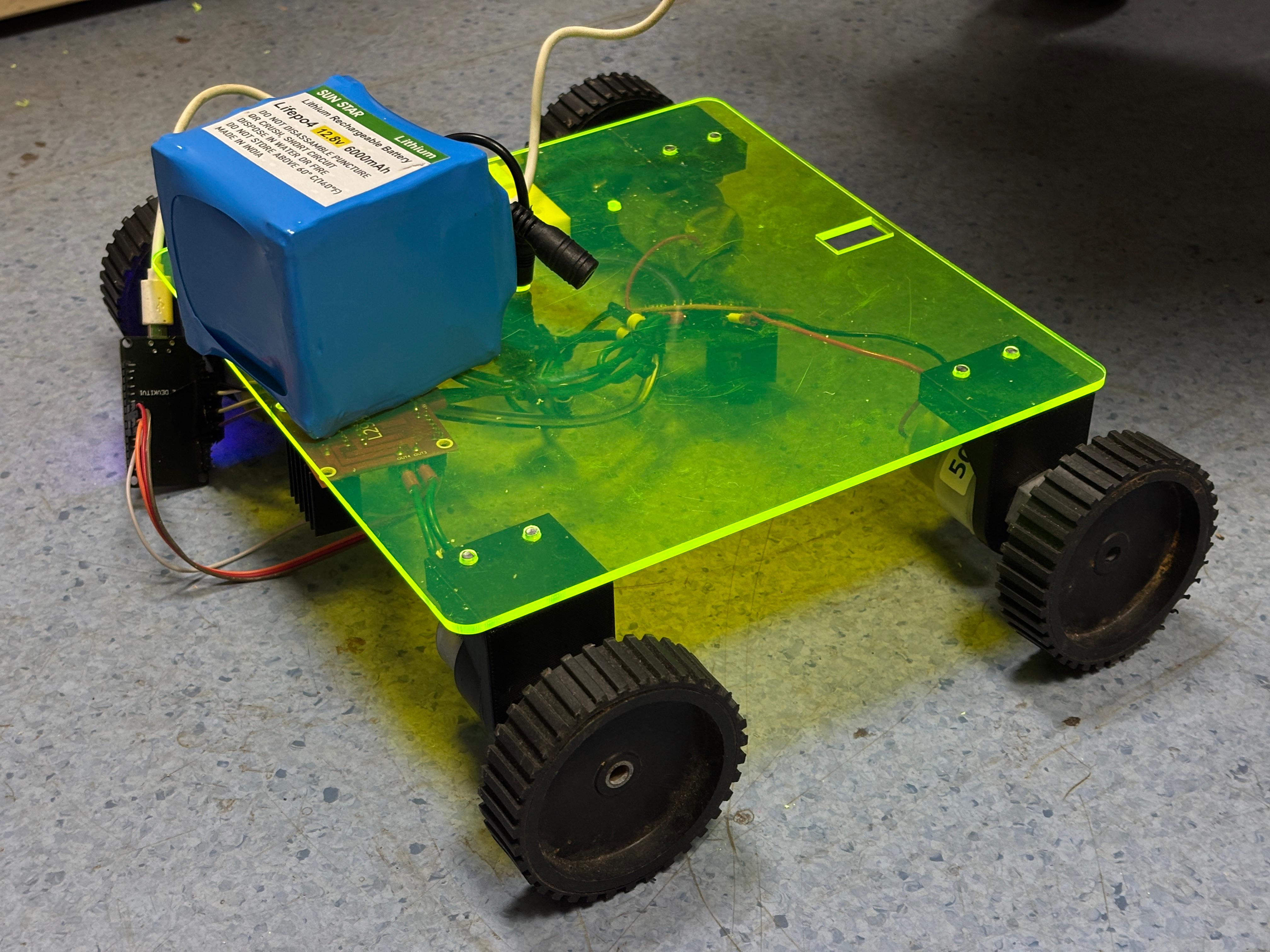
All four wheels were mounted onto the acrylic chassis, completing the mechanical assembly. With reduced weight and proper motor alignment, the system achieved smoother motion.
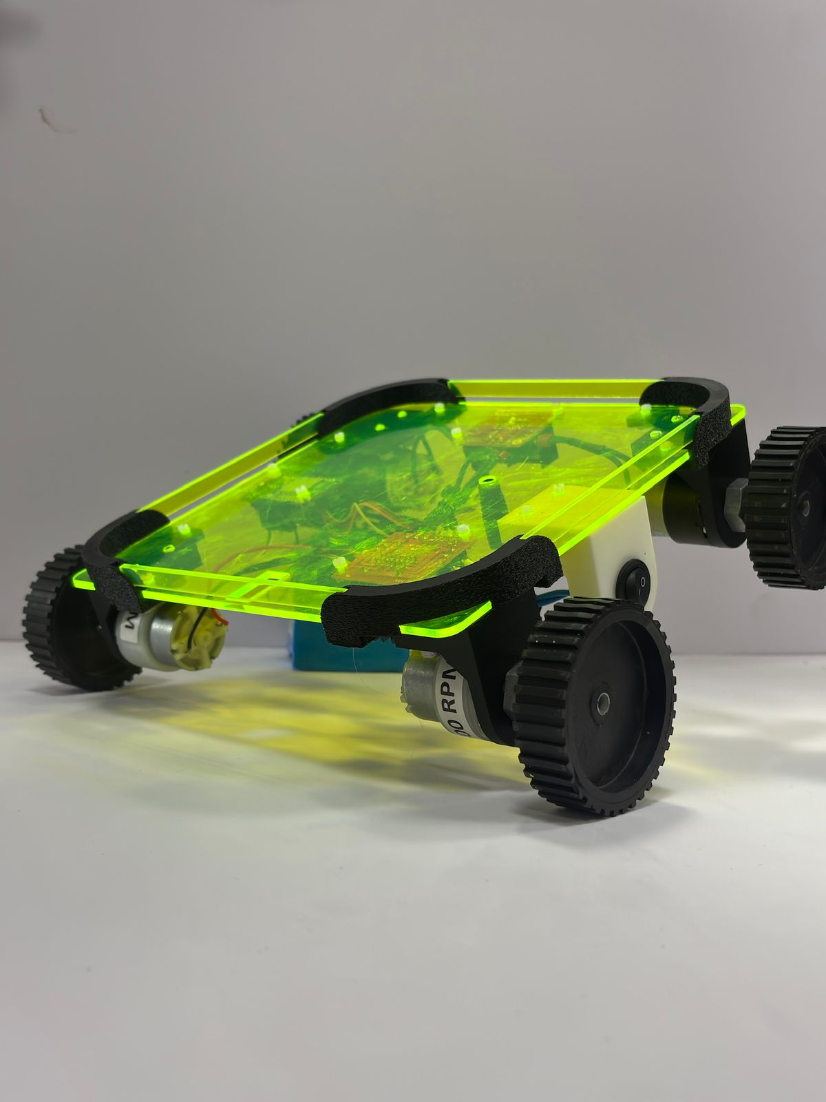
(Final Output)
The final robot integrates ESP32-based wireless control, motor driver, custom PCB, and lightweight chassis. It can now move in all directions via remote input and is suitable for applications like point-to-point delivery within indoor environments (e.g., offices or labs).