Week 13 Molding and Casting
CAD Modelling
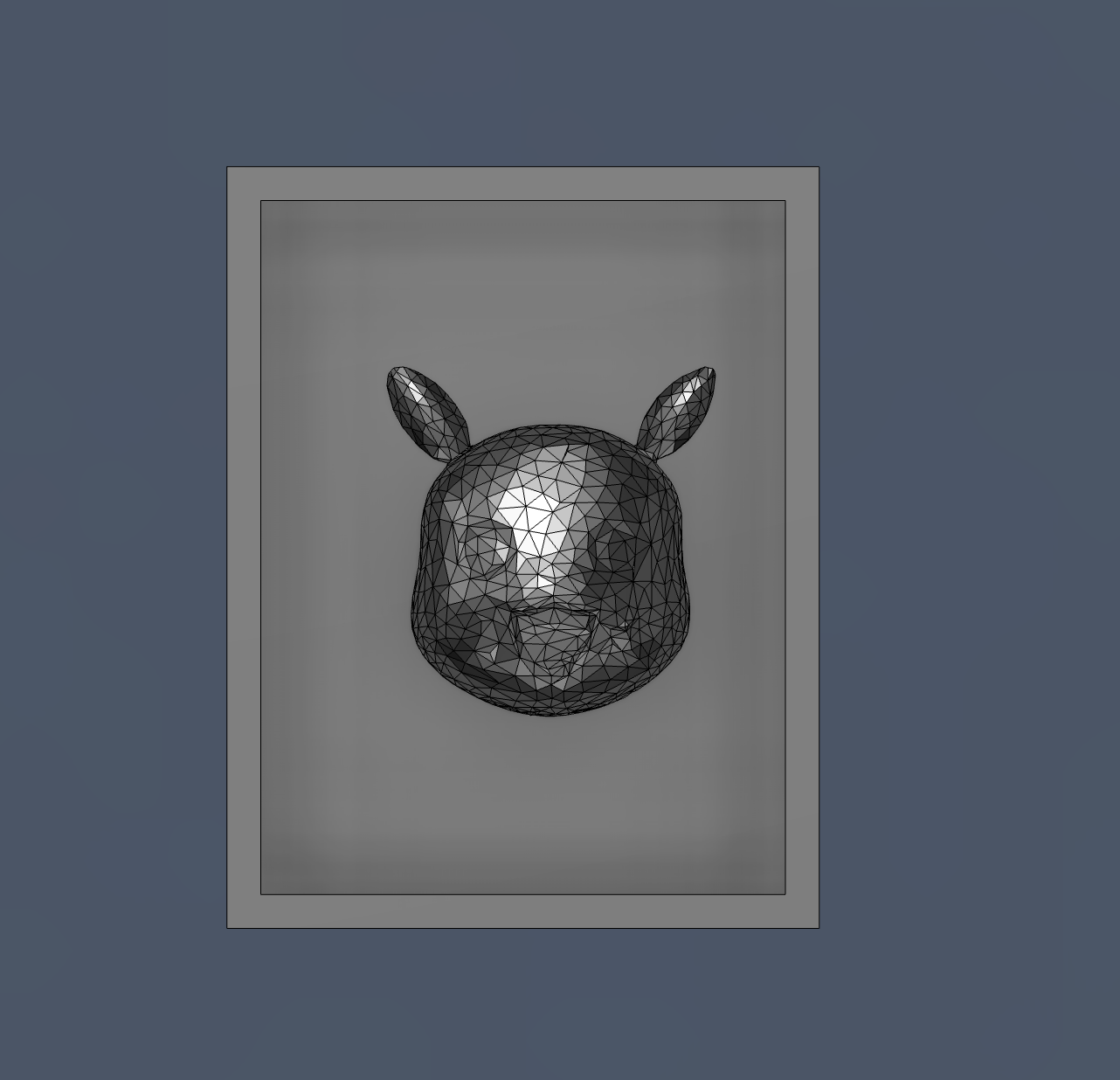
The process began with creating a 3D CAD model of the Pikachu form. The geometry was initially developed as a smooth solid body to capture the overall shape and proportions. At this stage, the focus was on achieving correct form, symmetry, and depth suitable for molding. The boundary frame around the model was also designed to define the mold limits and ensure proper containment of casting material later
 !
!
The solid CAD model was converted into a mesh format (triangulated surface). This step is essential for CAM processing, as most milling toolpath generators work better with mesh geometries. The mesh density determines how accurately the original shape is preserved. A finer mesh results in better surface quality but increases computation time and file size.
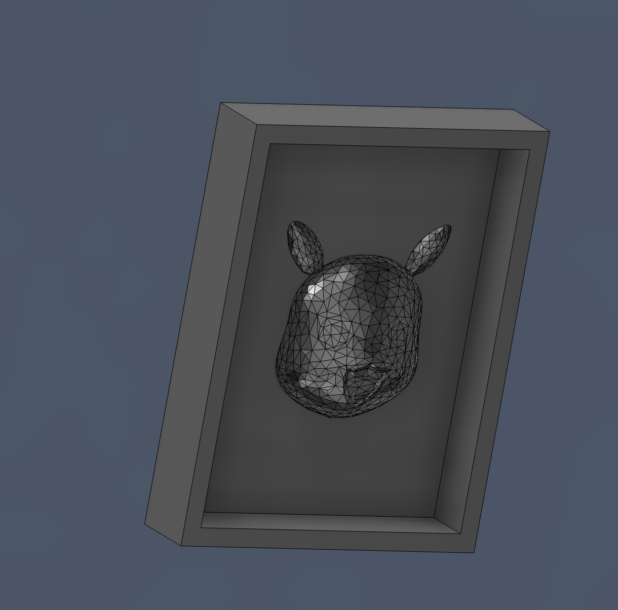
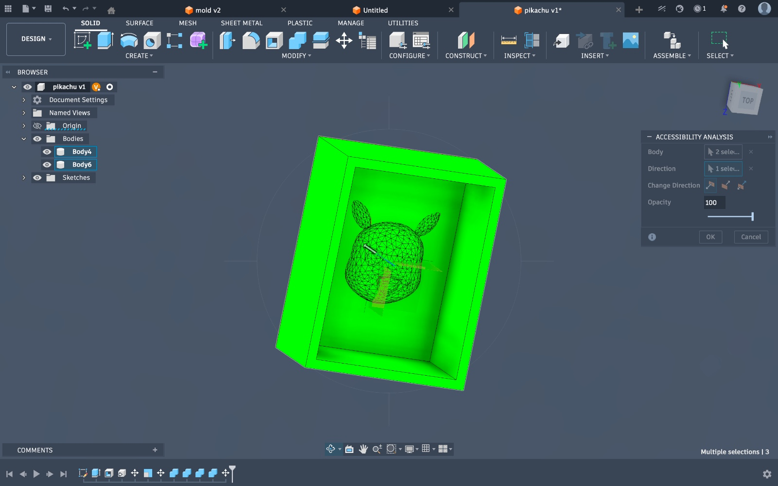
Image 3 – Assembly and Undercut Analysis
The model was placed within an assembly environment to analyze manufacturability, especially undercuts. During this step, it was observed that certain regions of the model extended beyond what a 3-axis CNC machine could reach. Undercuts are problematic because the tool cannot access those areas from a single vertical direction.
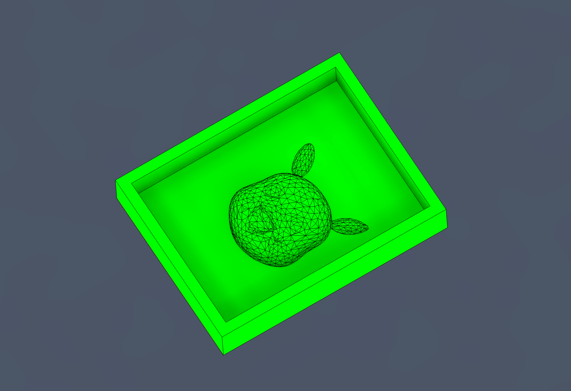
4 – Model Adjustment
Based on the undercut analysis, the lower portion of the model was modified to remove inaccessible geometries. This involved flattening or reducing overhanging features to ensure that all surfaces could be machined from a single direction. This step is critical to avoid tool collisions and incomplete cuts during milling.
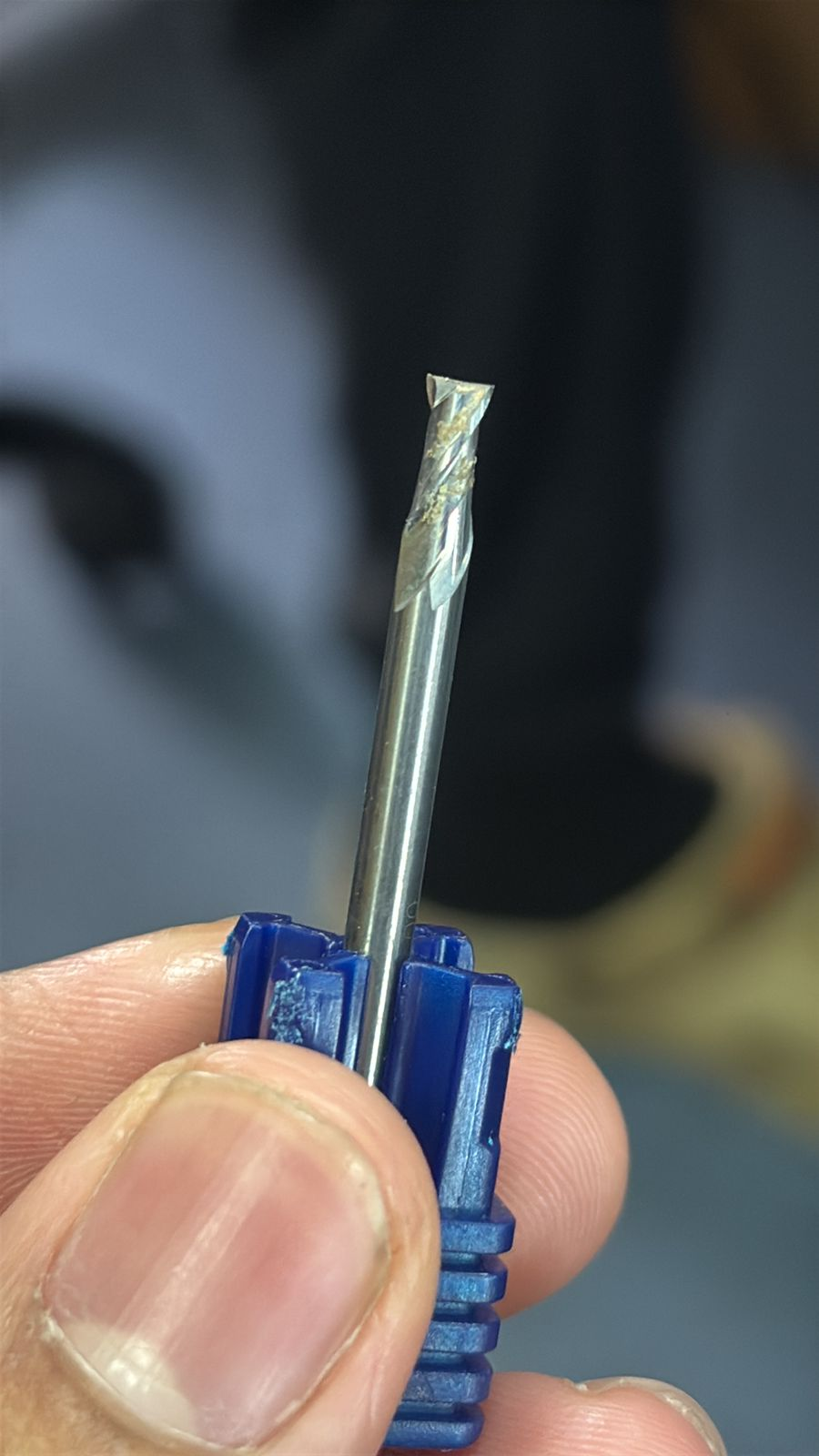
5 – Cutting Bit
The cutting bit shown is a flat end mill, typically used for roughing operations. It is designed to remove bulk material efficiently and create flat surfaces. However, due to its geometry, it cannot produce fine curved details, making it suitable only for the initial stages of machining
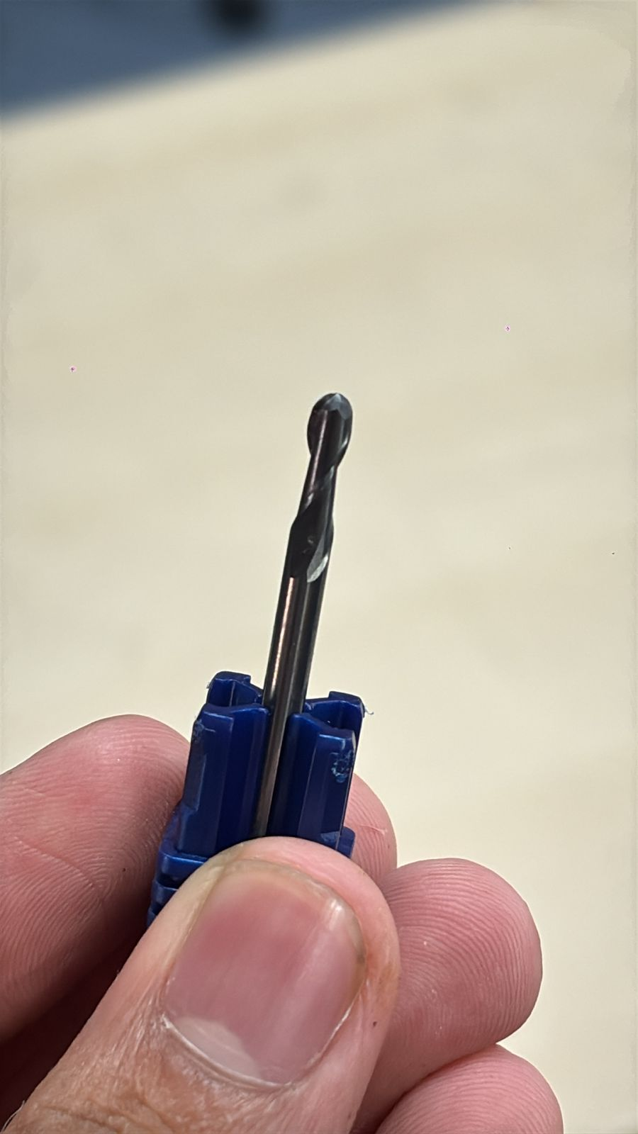
6 – Milling Bit
The milling bit shown here is a ball nose end mill. This tool is specifically used for finishing operations, especially for organic and curved surfaces like the Pikachu model. Its rounded tip allows smooth surface transitions and better detail reproduction compared to flat end mills.
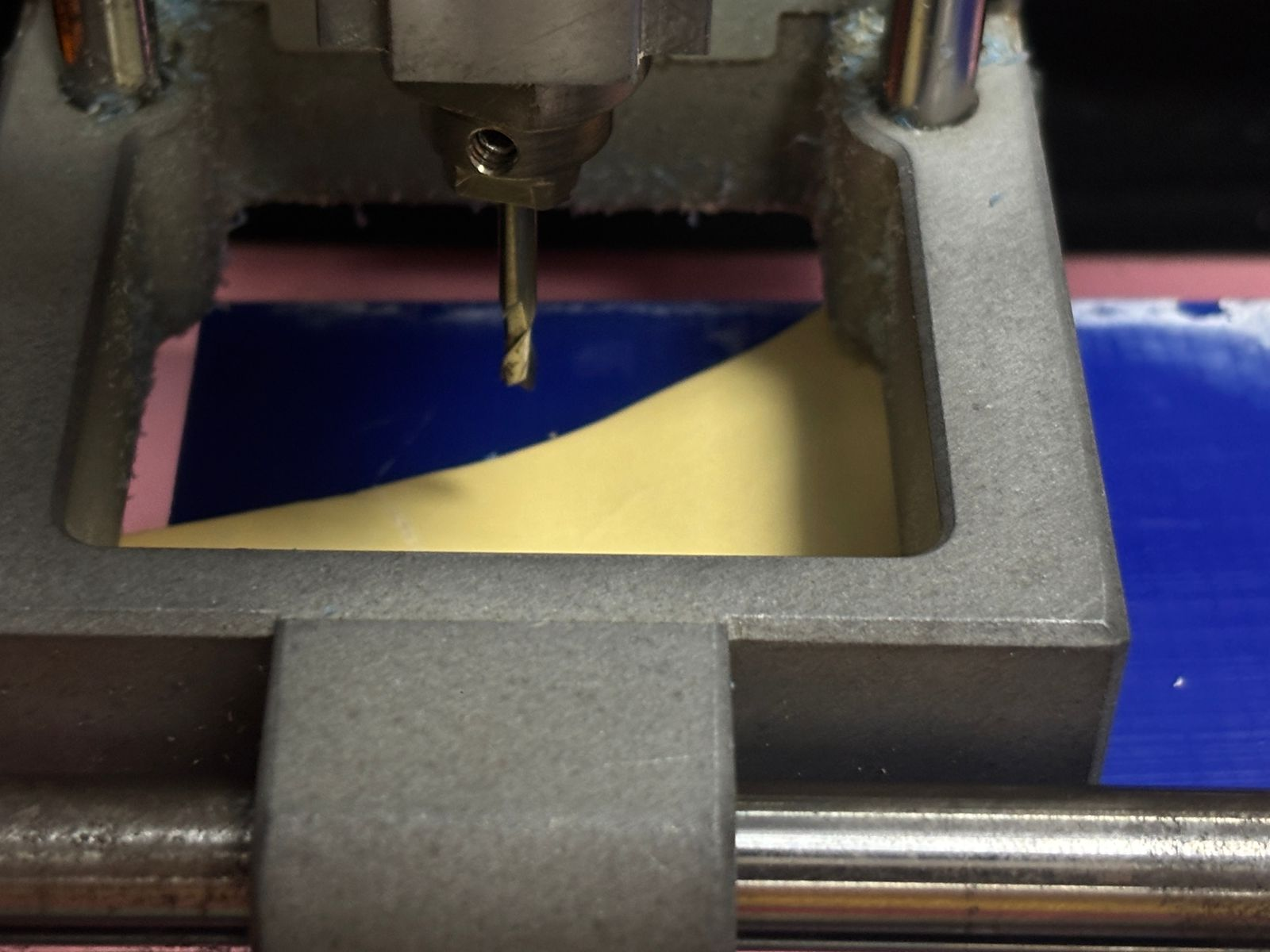
7- Cutting Process
The machining process was carried out using a CNC milling machine. The tool moves along predefined toolpaths to remove material layer by layer. The workpiece, in this case modeling wax, is gradually shaped into the negative mold of the design. Proper clamping and tool calibration are essential to ensure accuracy and avoid vibrations.
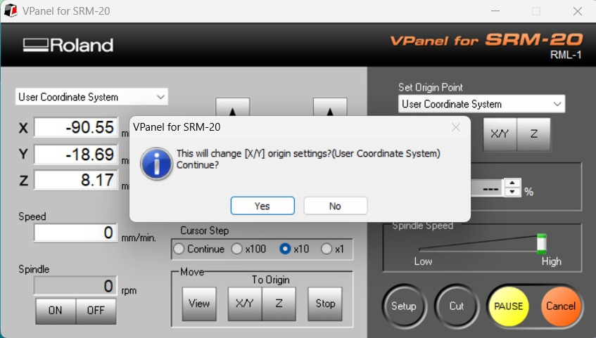
8 – Setting Origin (X, Y, Z)
The origin point of the machine was set using the control panel interface. The X and Y axes define the horizontal position, while the Z-axis defines the vertical reference (usually the top surface of the material). Accurate origin setting ensures that the toolpath aligns perfectly with the physical workpiece.
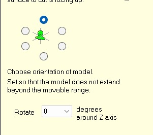
9 – View Orientation
The model orientation interface allows selection of the top surface and viewing angle before generating toolpaths. This ensures that the correct face of the model is machined first. Proper orientation prevents errors such as inverted cuts or incorrect depth machining.
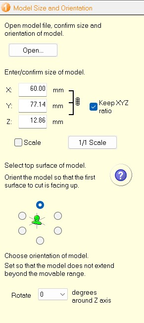
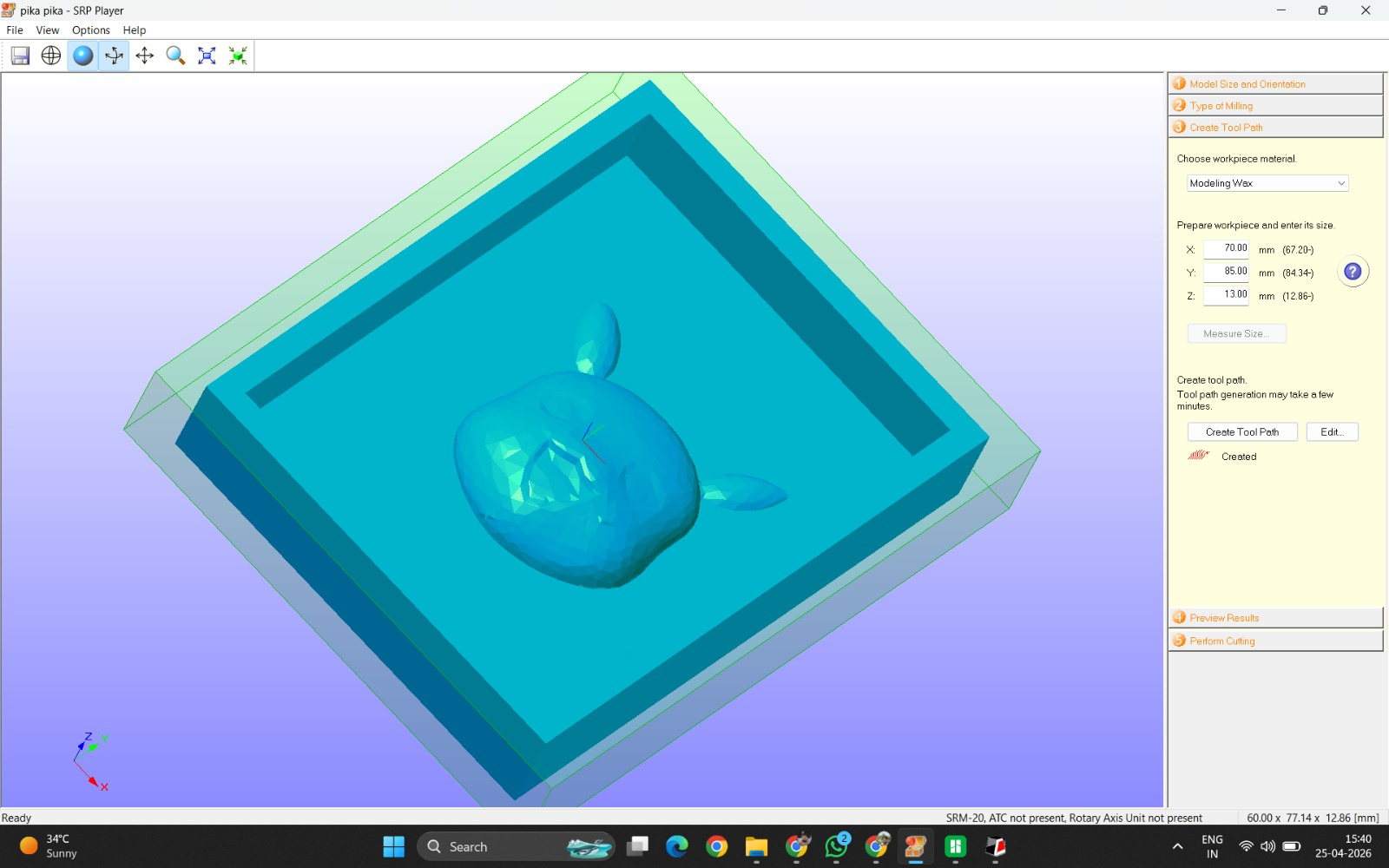
10 – Model Size and Orientation
This step involves confirming the dimensions (X, Y, Z) of the model and ensuring it fits within the machining area. Maintaining scale (1:1) is important to preserve design accuracy. The model is also aligned so that the most critical surface is facing upward for machining.
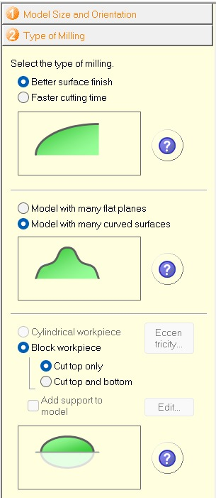
11 – Type of Milling (Options Explanation)
This interface provides multiple options for machining strategy. The “better surface finish” option prioritizes quality over speed, resulting in finer toolpaths. The selection between flat and curved surface models helps optimize tool movement. Choosing “block workpiece” defines the stock geometry, while options like “cut top only” ensure material is removed only from one side. These settings directly impact machining time and output quality.
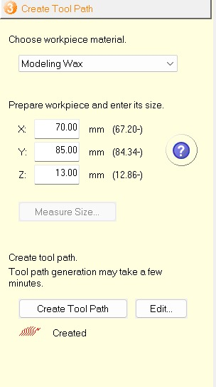
12 – Material Selection and Size
The material selected is modeling wax, which is commonly used for mold making due to its ease of machining and smooth finish. The stock dimensions (X, Y, Z) are defined slightly larger than the model to provide machining allowance. This extra margin ensures complete cutting without risking damage to the tool or incomplete geometry.
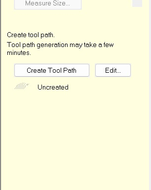
13 – Editing Tool Path
In this step, the toolpath settings were accessed by clicking on the “Edit” option. This allows modification of machining strategies such as tool selection, cutting parameters, and operation type. Editing the toolpath is essential to control how the machine removes material, ensuring both efficiency and surface quality.
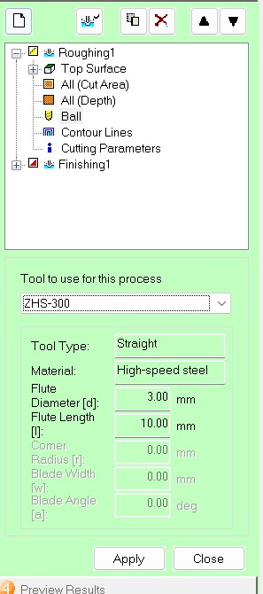
14 – Toolpath Structure (Roughing + Finishing)
The software displays a hierarchical toolpath structure consisting of Roughing and Finishing operations. Roughing removes bulk material using larger step sizes, while finishing refines the geometry. Parameters such as top surface, cut area, depth, contour lines, and cutting conditions are defined here to guide the machining process.

15 – Tool Selection (Flat End Mill for Roughing)
For the initial cutting phase, a straight (flat) end mill tool was selected (ZHS-300). This tool is made of high-speed steel and has a diameter of 3 mm. It is used for roughing because it can efficiently remove large amounts of material quickly, though it does not provide a smooth surface finish.
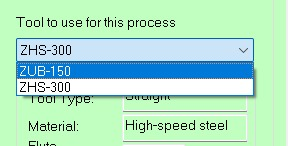
16 – Tool Library Options
The available tool options (such as ZUB-150 and ZHS-300) were reviewed. These represent different tool geometries and sizes. Selecting the correct tool is critical because it directly affects cutting accuracy, surface finish, and machining time.
17 – Confirming Roughing Tool Parameters
The selected tool parameters, including diameter, flute length, and material, were confirmed. These values determine how deep and how aggressively the tool can cut. Proper configuration prevents tool breakage and ensures stable machining.
18 – Toolpath Preview
After generating the toolpath, a simulation preview was displayed. This shows how the tool will move across the material and remove layers. It helps verify that there are no collisions, missed regions, or incorrect depths before actual machining begins.
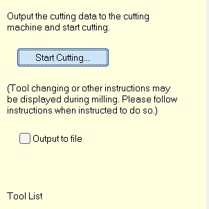
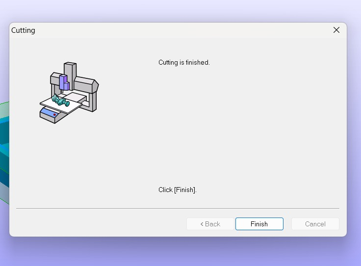
19 – Starting the Cutting Process
The cutting process was initiated by selecting “Start Cutting.” At this stage, the machine receives the toolpath instructions and begins executing them. Any required tool changes or instructions are displayed during this process.
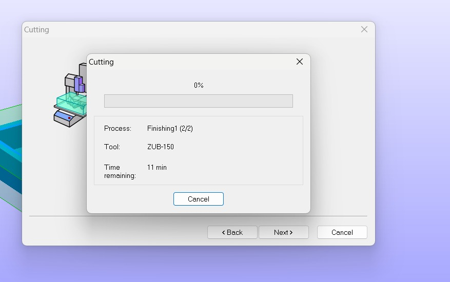
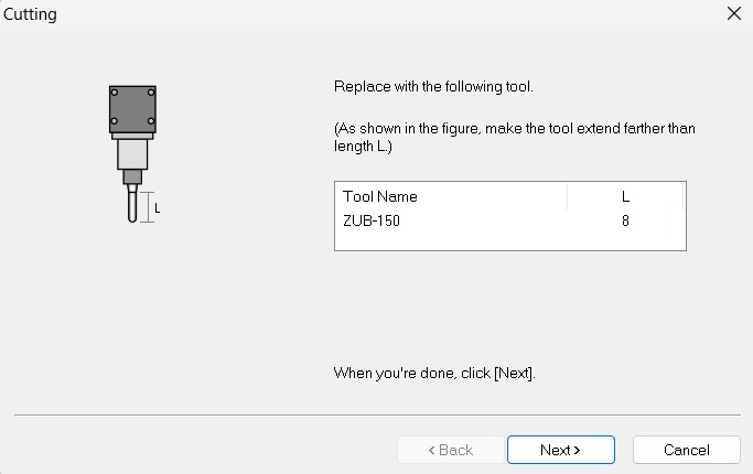
20 – Finishing Operation Progress
The machine begins the finishing phase, using a finer tool (ZUB-150). The progress window shows the percentage completed and estimated remaining time. Finishing is slower but crucial for achieving smooth surfaces and detailed features.
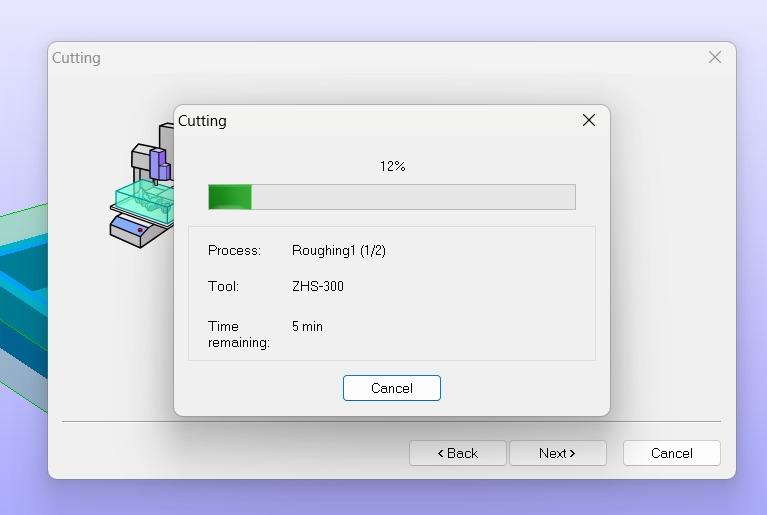
21 – Roughing Operation Progress
The roughing phase is shown here, where the machine removes bulk material using the flat end mill (ZHS-300). This stage is faster and focuses on shaping the general cavity rather than fine details.
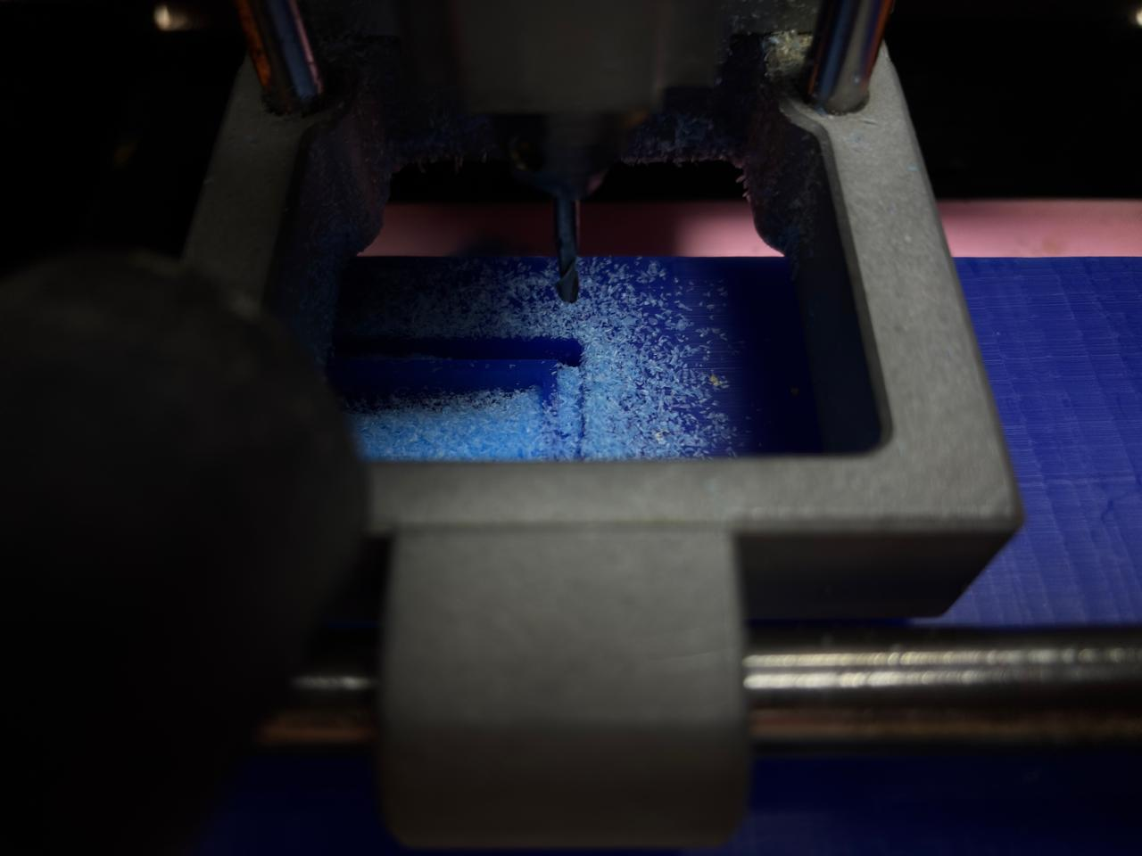
22 – Material Removal in Process
The physical cutting process is visible here. The milling bit removes layers of modeling wax, producing chips. This stage clearly shows the difference between roughing (large material removal) and finishing (fine detailing).
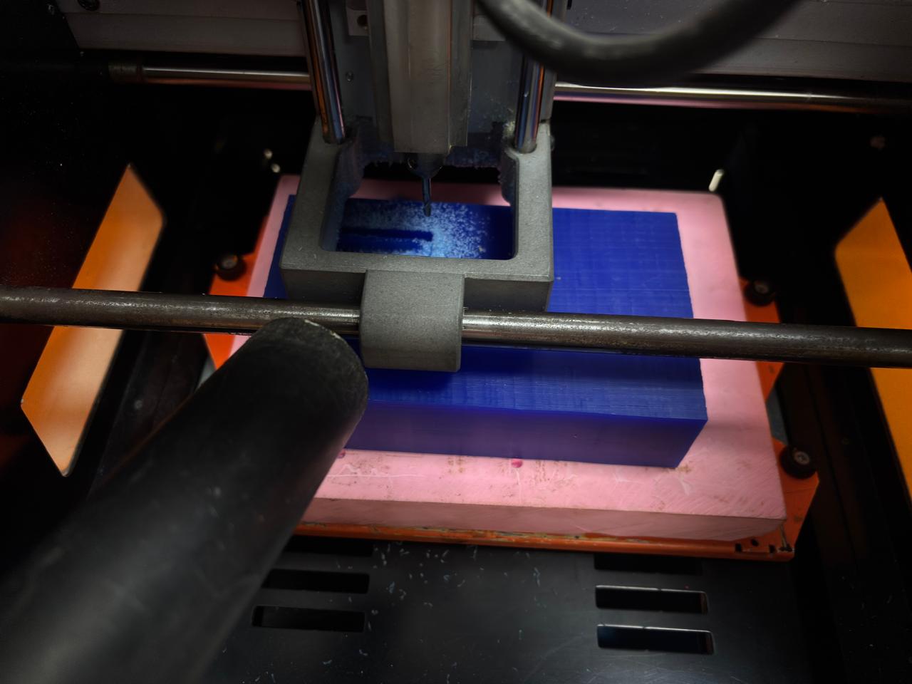
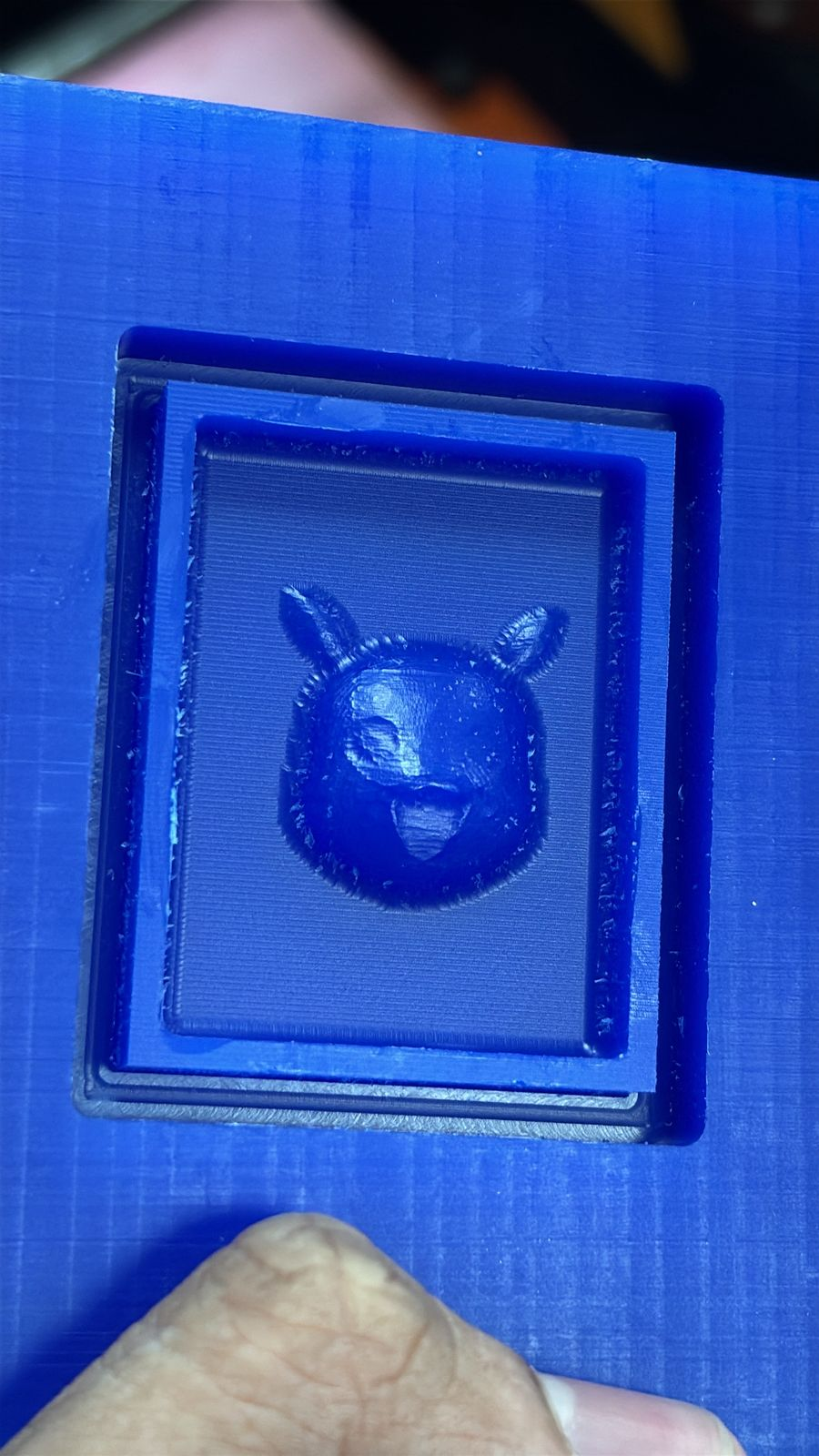
26 – Final Output (Milled Mold)
The final milled mold in modeling wax is shown here. The Pikachu geometry is clearly visible with improved surface finish after the finishing pass. Minor tool marks may still be present, which can be further refined if needed. This mold is now ready for the casting process.
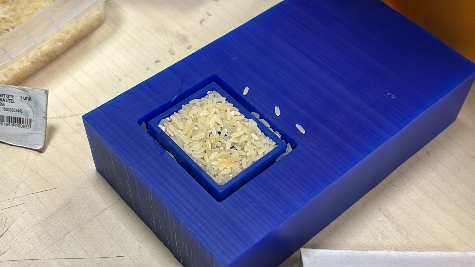
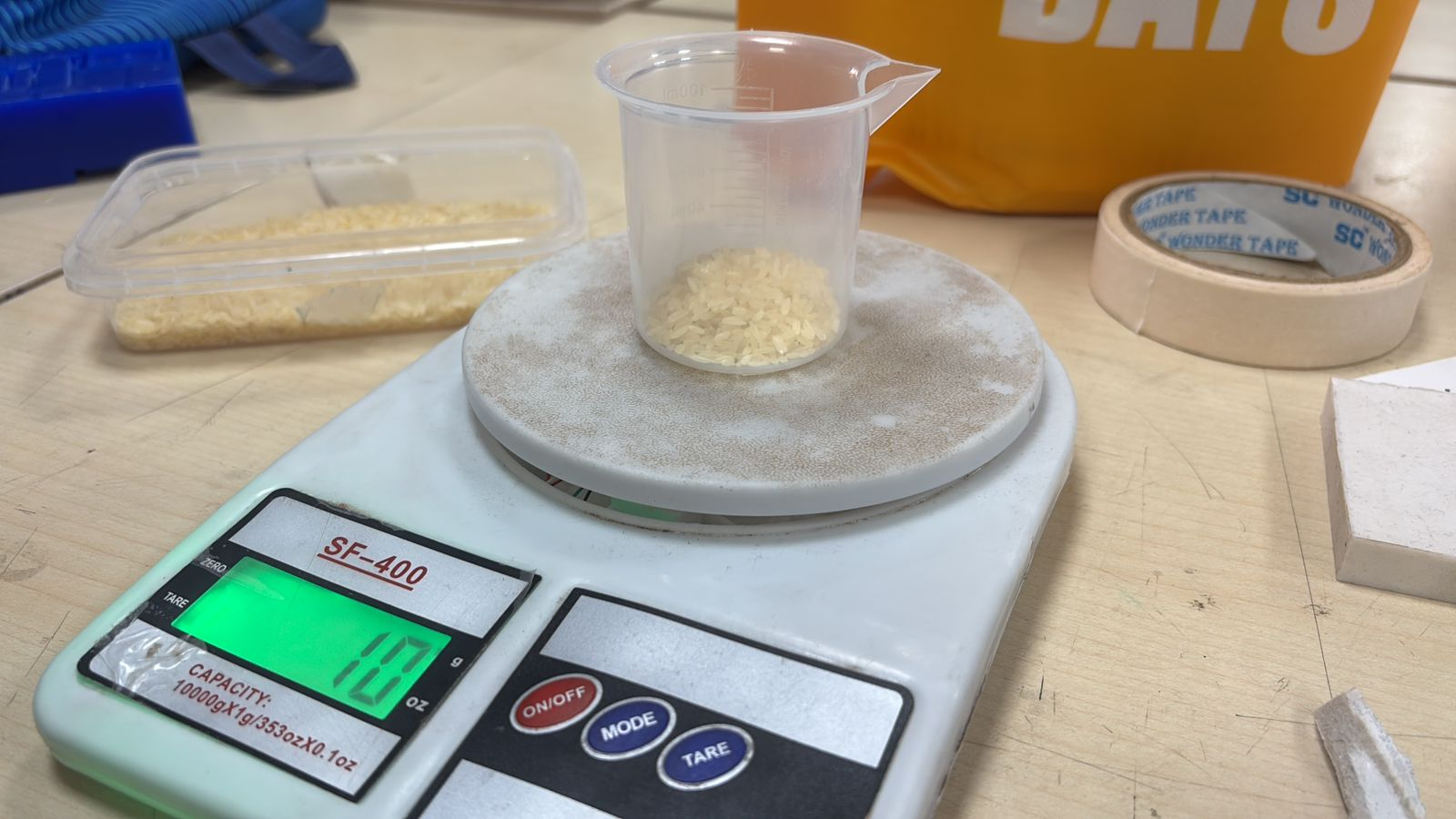
27 – Preparing the Mold for Casting
After completing the milling process, the mold cavity was cleaned and prepared for casting. Small grains (rice) were used to estimate the volume of the cavity. This helps in calculating the approximate amount of silicone required, reducing material wastage.
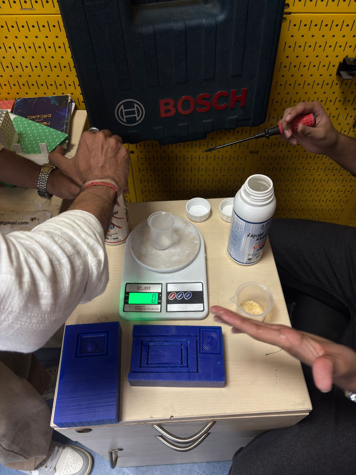
28 – Measuring and Setup for Mixing
All required materials were arranged, including the digital weighing scale, mixing cups, and silicone rubber components. The mold was placed nearby for easy pouring. Proper setup ensures accuracy in measurement and avoids contamination during mixing.
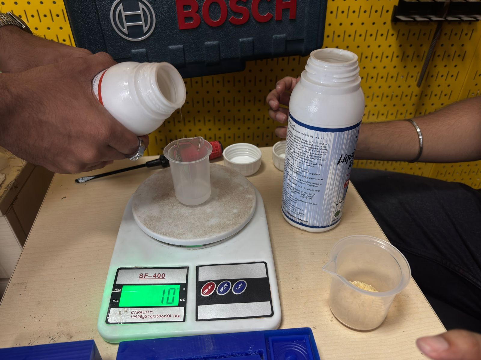
29 – Pouring Silicone (Part B)
The silicone rubber Part B was first poured into a measuring cup placed on a digital scale. The weight was monitored to ensure precise measurement. Maintaining correct proportions is critical for proper curing.
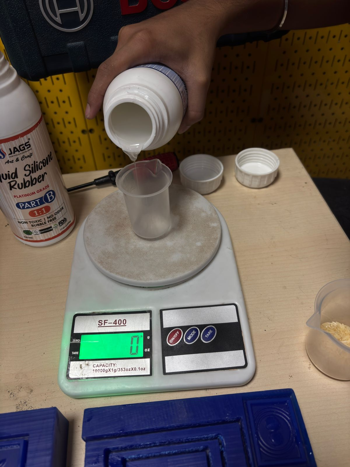
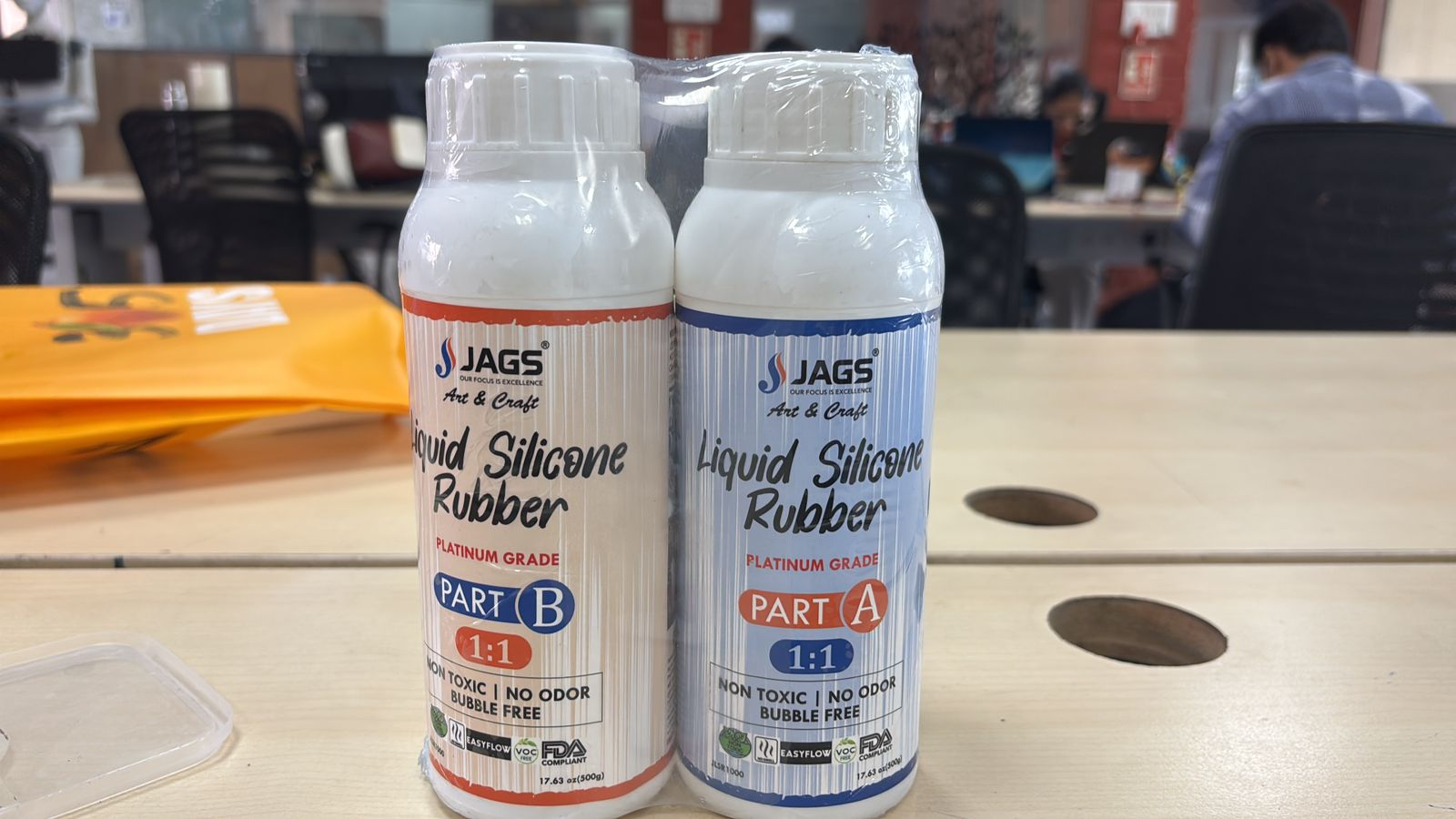
30 – Silicone Material (Part A & Part B)
The material used is liquid silicone rubber (platinum grade), consisting of two parts: Part A and Part B. These components must be mixed in a 1:1 ratio. The material is non-toxic, low odor, and suitable for mold-making applications due to its flexibility and fine detail reproduction.
31 – Measuring Volume Using Grain Reference
The previously measured grain volume was used as a reference to determine how much silicone is needed. This practical method ensures that enough material is prepared to completely fill the mold without overflow.
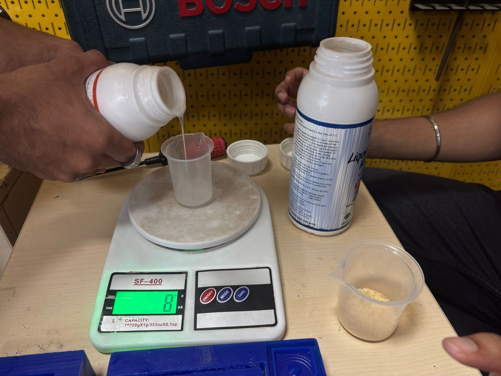
32 – Pouring Silicone (Part A)
After measuring Part B, an equal amount of Part A was added to the same cup. Maintaining a 50:50 ratio is essential for proper chemical curing. Any deviation can result in incomplete curing or a sticky surface.
33 – Completing the Mixing Ratio
Both Part A and Part B were combined in equal proportions. The mixture was then stirred thoroughly (not shown in image but implied) to ensure uniform consistency. Proper mixing is crucial to activate the curing reaction.
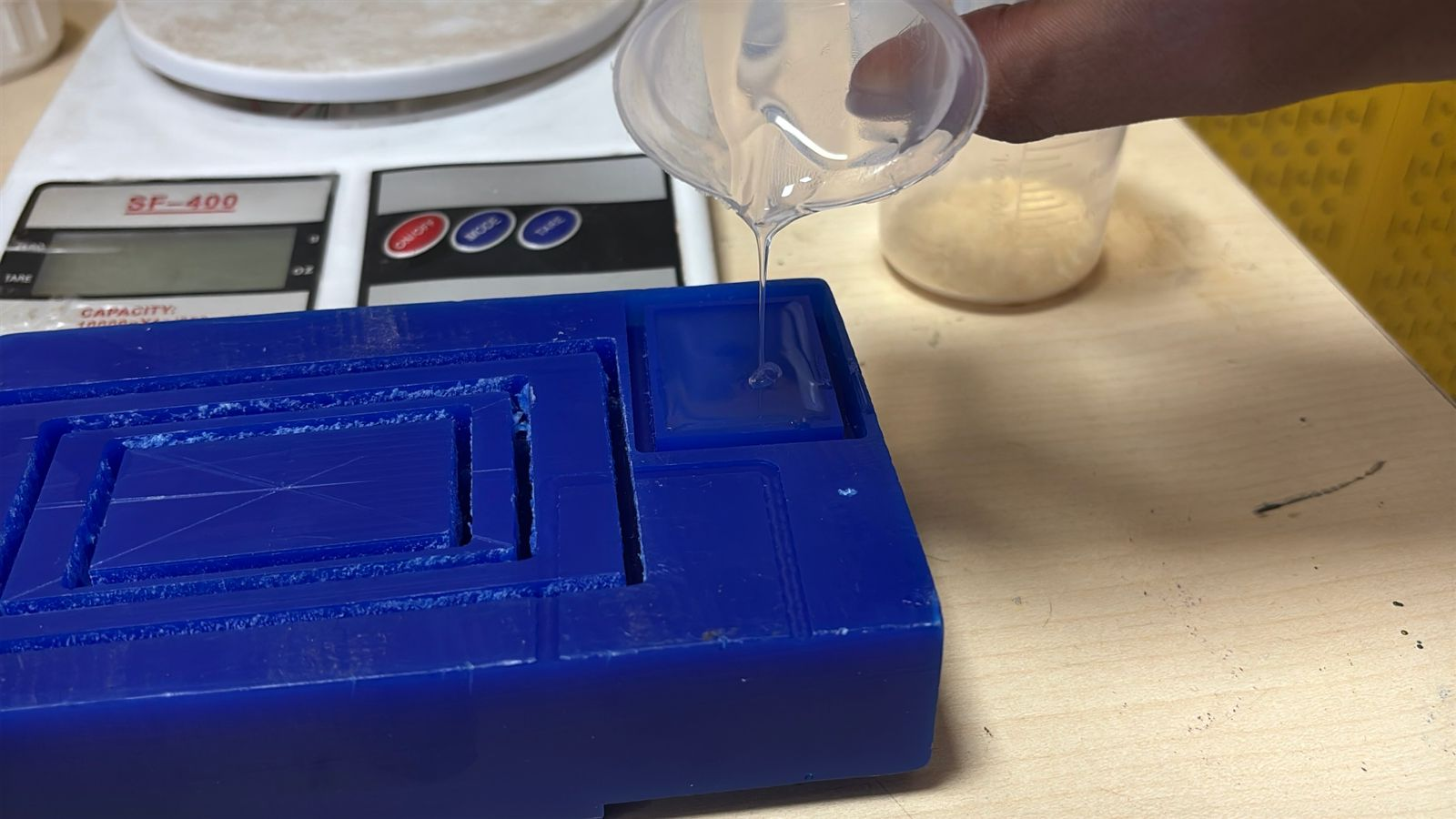
34 – Pouring into the Mold
The mixed silicone was slowly poured into the mold cavity. Pouring was done carefully to minimize air bubbles and ensure the material flows into all fine details of the mold.
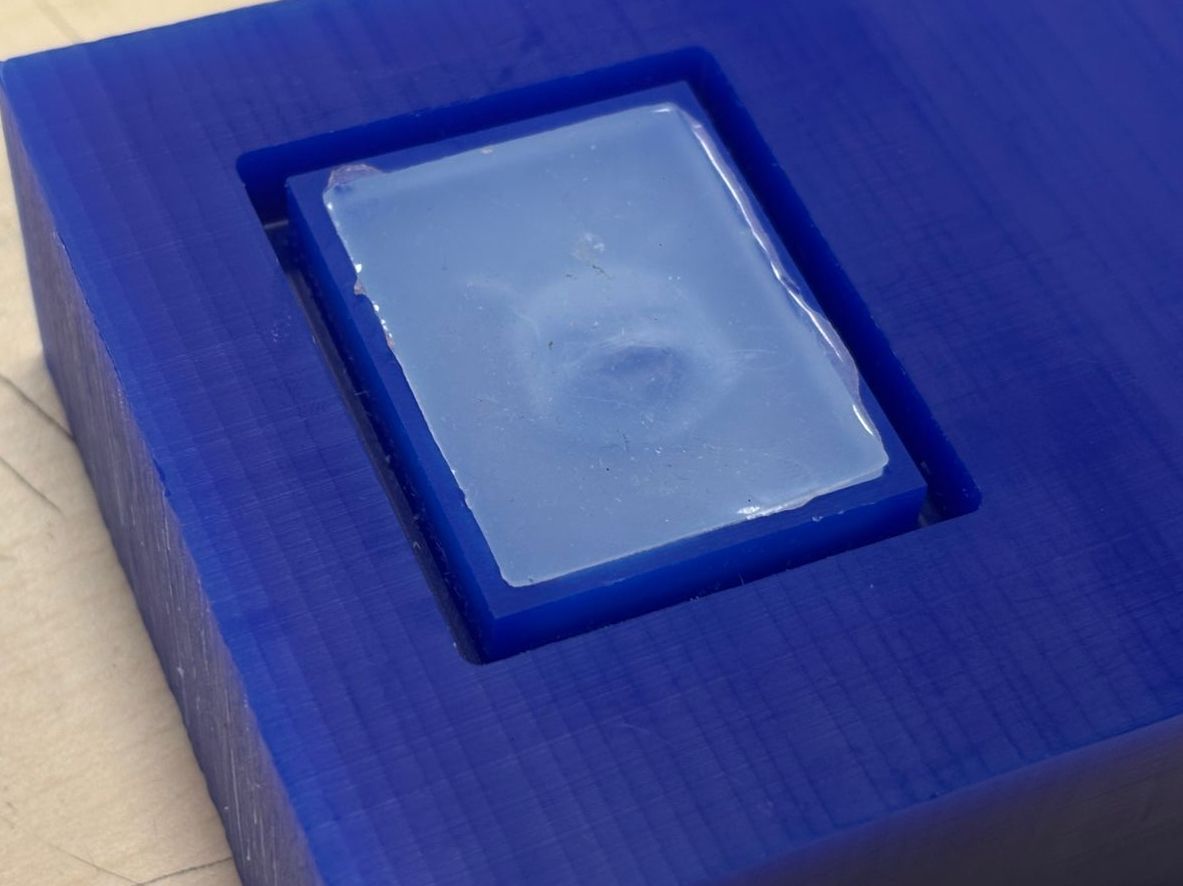
35 – Initial Curing Stage
After pouring, the silicone begins to settle and level itself within the mold. At this stage, the material is still liquid and requires time to cure without disturbance.
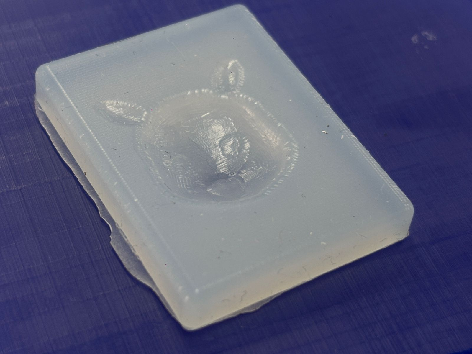
36 – Final Silicone Mold (After Curing)
After approximately 12–16 hours, the silicone fully cured and solidified. The mold was then removed from the wax block. The final result shows a flexible silicone mold with the Pikachu geometry clearly captured, ready for further casting processes.