Week 3 Computer Controlled Cutting
Laser Cutter Week 3
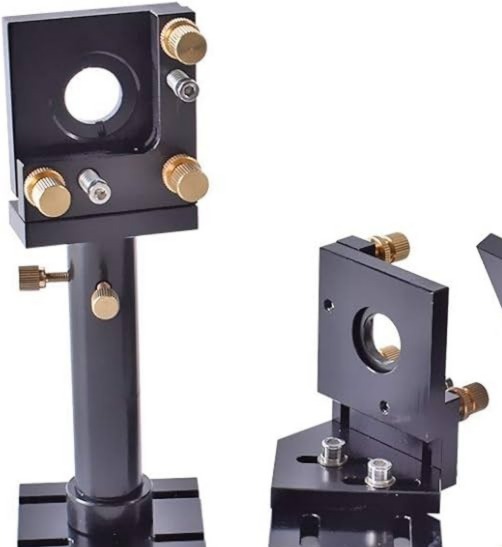
This is where the actual laser beam is born.
The long glass tube generates the laser light. From there, the beam doesn’t directly go to the material. Instead, it hits these small mirrors mounted at 45°. These mirrors keep bouncing the beam around corners until it reaches the cutting head.
I realized the tube is fixed, while the head moves. So the mirrors basically “guide” the light wherever the head travels.
It’s almost like playing pool with light.
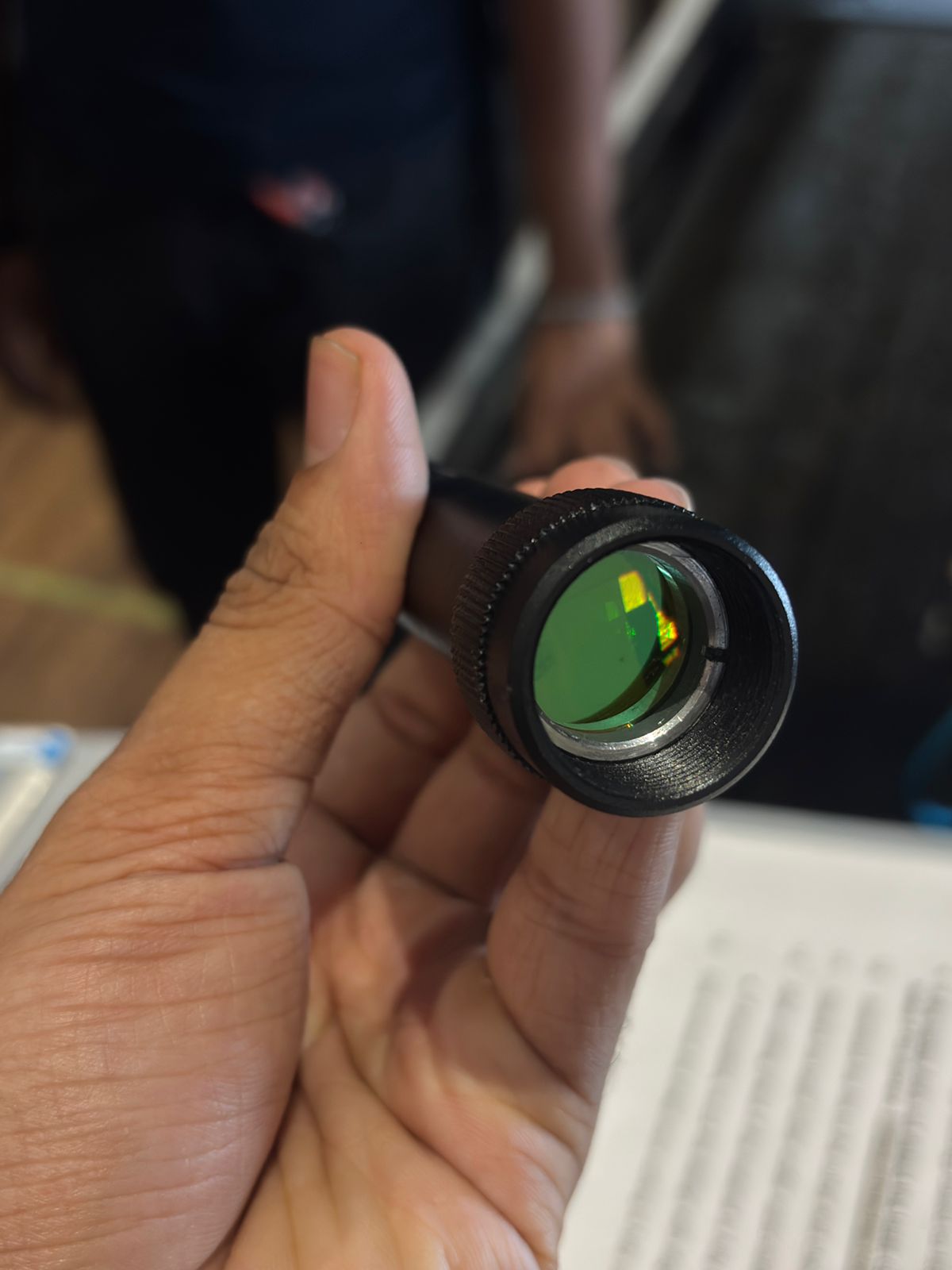
This small lens looks harmless, but it’s actually super important.
The laser beam coming from mirrors is kind of wide. This lens concentrates it into a tiny point. When the energy gets focused into such a small spot, the temperature becomes high enough to burn or cut material.
It reminded me of using a magnifying glass to burn paper in sunlight — same idea, just way more powerful.
Without this lens, the machine would probably just heat the material instead of cutting it cleanly.
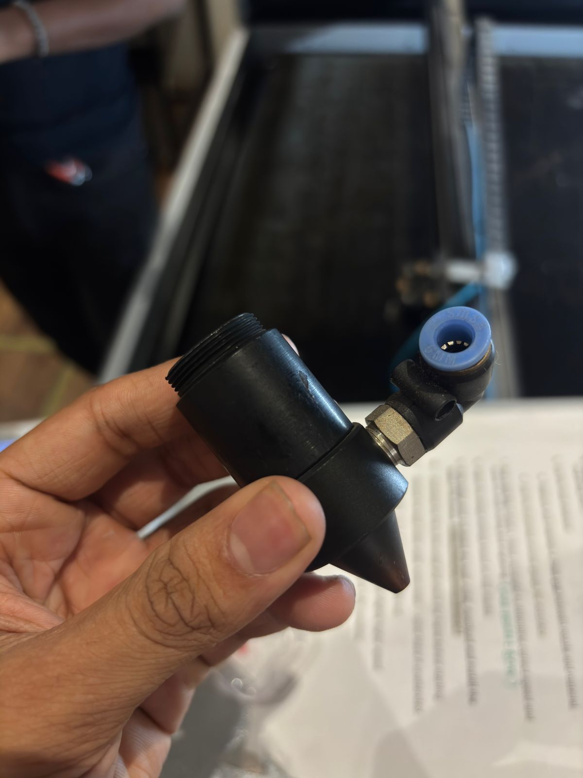
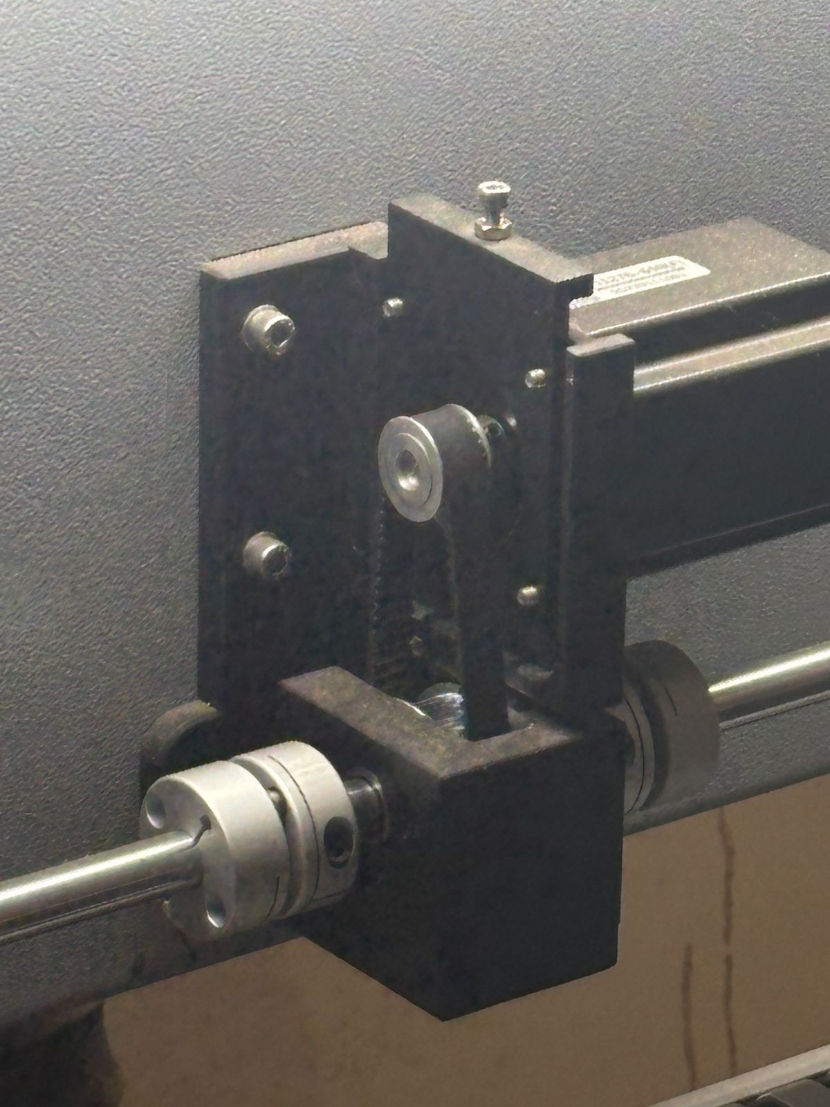
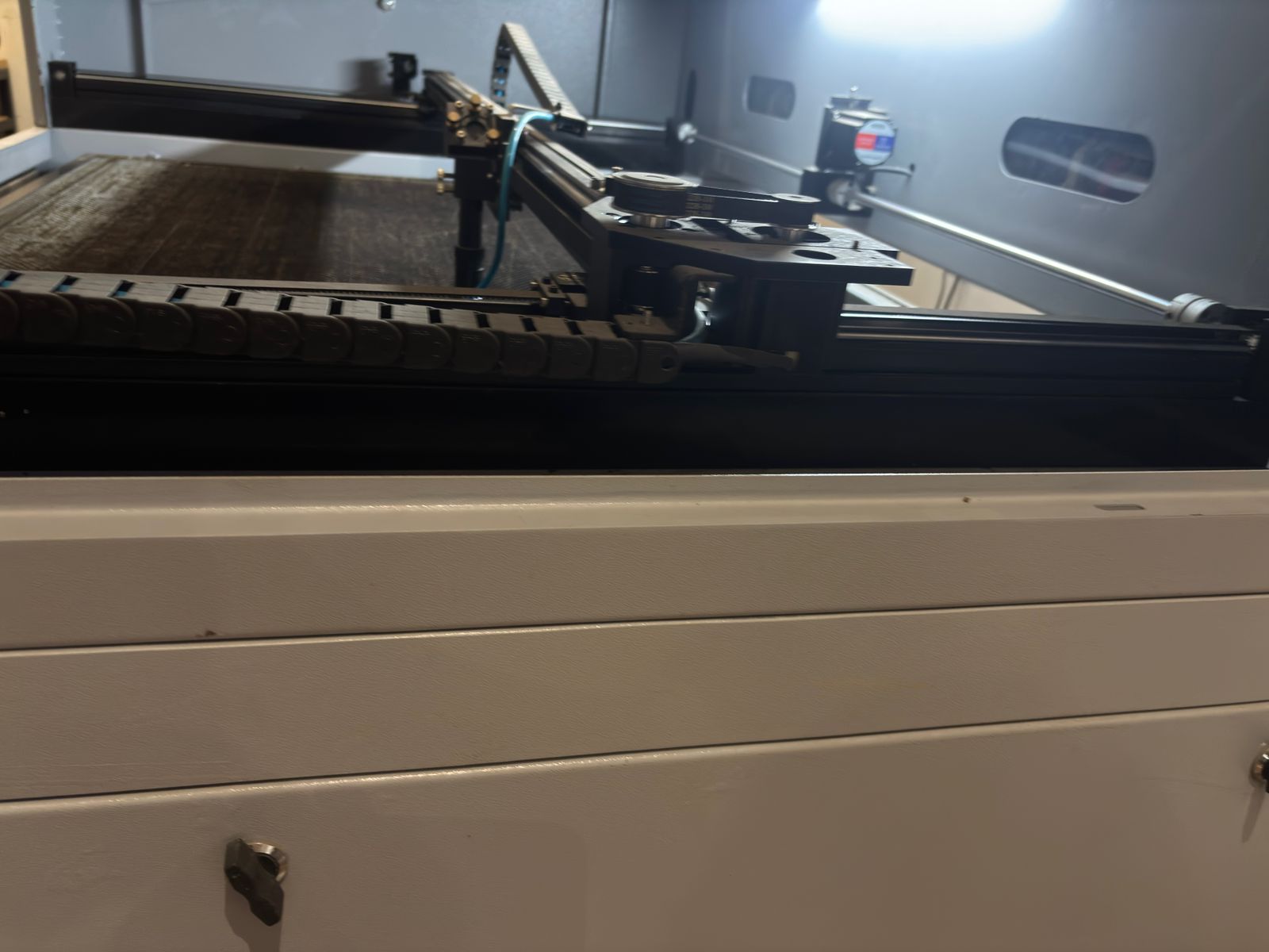
This part made everything click for me. It’s basically the mechanical movement system. There are rails, belts, and stepper motors that move the head left-right and front-back. Exactly like how an inkjet printer moves. So the laser itself doesn’t “draw” — the motors move the head, and the laser just fires while moving. Which means: 👉 It’s literally a CNC machine that uses light instead of a tool bit
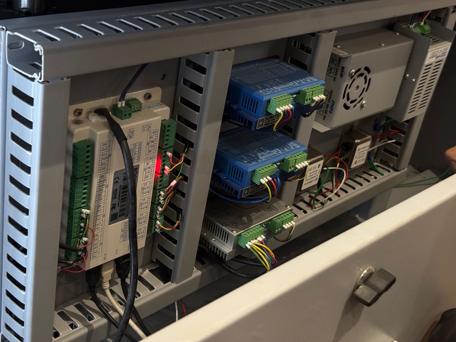
This section looks messy but it’s the brain of everything.
Inside here: motor drivers power supply controller boards lots of wiring
When we press “Start” on the computer, signals come here first. Then these boards decide: how fast motors move when the laser turns on/off how strong the laser fires
So basically:
👉 Computer gives instructions
👉 Electronics execute them
👉 Motors + laser do the job
Without this panel, the machine wouldn’t even move.
Individual
Exploring Foldable Laser-Cut Structures → Finding a Modular Kit
I started this week by looking at foldable laser-cut structures.
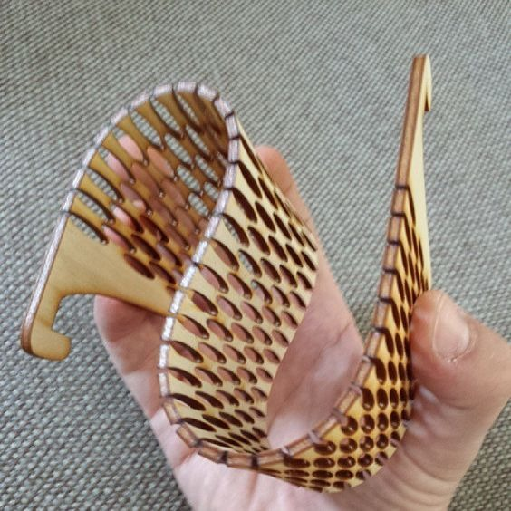
I was really curious about how flat sheets can bend and transform into 3D forms just by changing the cutting pattern. I explored living hinges, perforations, and flexible cuts that allow wood or cardboard to curve smoothly.
The idea was simple: Can I make a small foldable storage compartment that opens like a fan and holds tiny objects like nuts, bolts, or bits?
Something compact, satisfying to open, and easy to fabricate
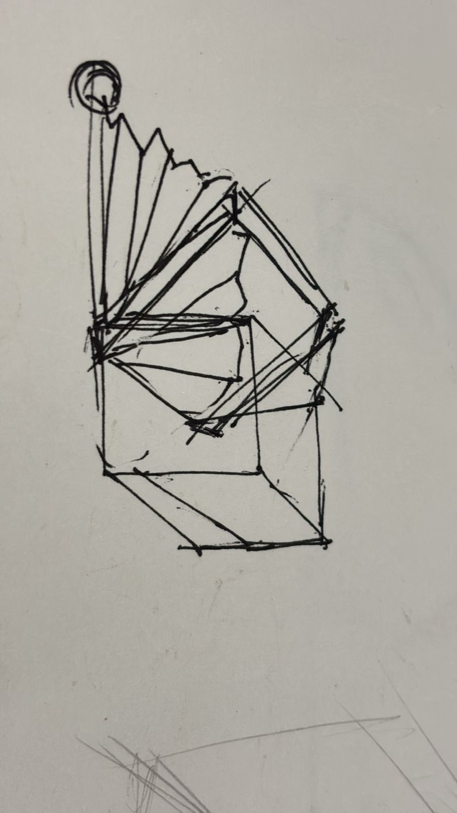
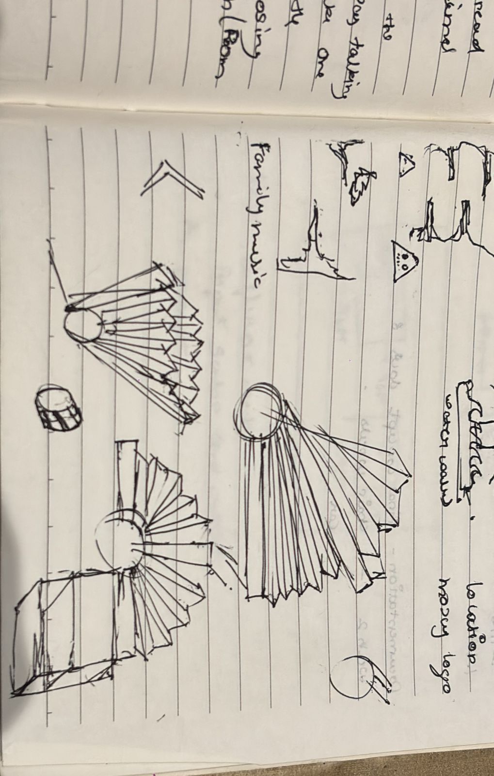
First experiments – folding tests
I began by making quick exploratory sketches to test different fold patterns and understand how the material behaves under bending. I experimented with straight scan lines, continuous cuts, and long hinge slots, observing how each pattern influenced flexibility. Initially, these patterns allowed smooth bending, but after repeated folding, the material started to weaken, showing signs of tearing and reduced structural integrity. This helped me realize the importance of balancing flexibility with strength in the design. Once I finalized the geometry and optimized the parameters in CAD, I exported the design file and imported it into RDWorks, the software used to control and communicate with the laser cutter, preparing it for fabrication.
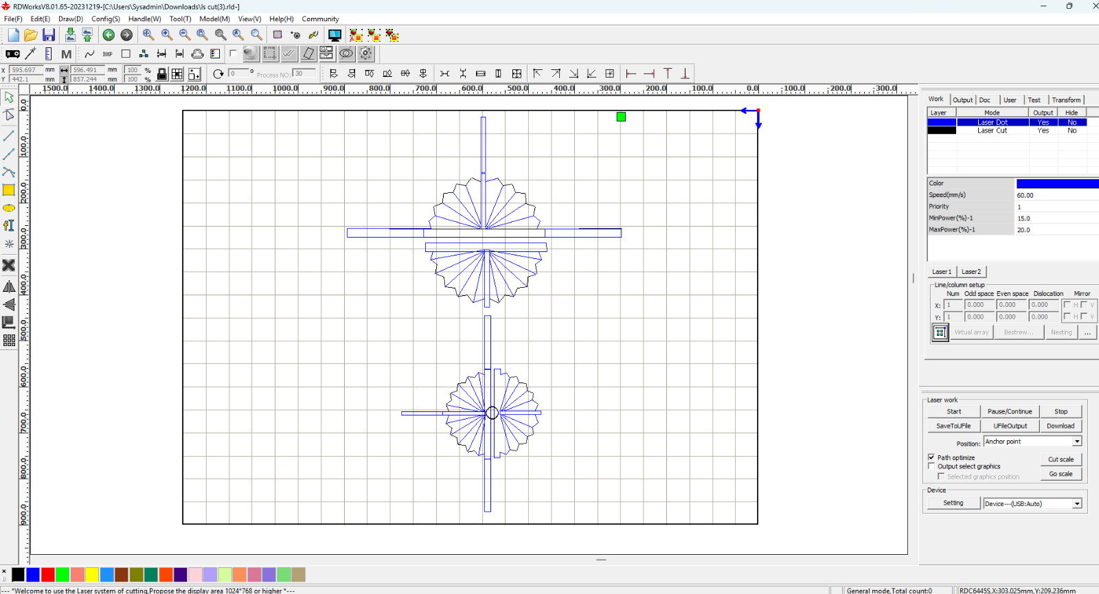
This stage is less about designing and more about preparing the file for fabrication.
Here, I arranged all the parts inside the machine’s working area and checked how efficiently they fit on the sheet. Since laser cutting time and material both matter, nesting and spacing became important.
I then separated the drawing into different layers:
Cut lines → full through cuts
Dot/score lines → fold or guide lines
Each layer gets different speed and power settings.
This allows the laser to treat every line differently — some cuts go all the way through, while others only mark or weaken the surface for bending.
I continued experimenting by refining the hinge design, replacing long continuous cuts with dotted or perforated patterns. This approach helped distribute stress more evenly, reducing stress concentration points and significantly improving flexibility. The material responded much better, with smoother folds and increased durability over repeated use. Technically, the solution was effective and performed well, but something still felt misaligned. During this process, I realized that I had drifted away from my original objective. I had become deeply focused on material behavior and hinge optimization, while the initial brief was centered on a different design intent
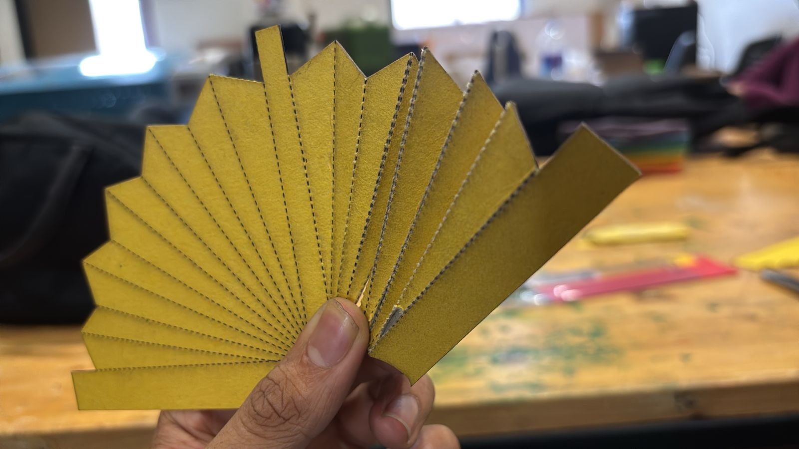
Image 2
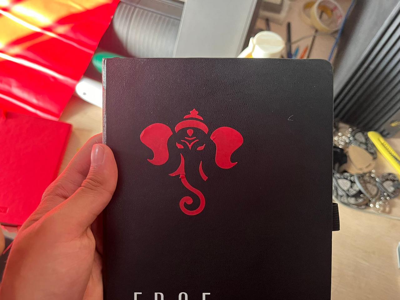
 I started exploring vinyl cutting by designing a simple Ganesh graphic and applying it as a stencil on a notebook surface. This helped me understand how clean vector paths translate into precise cuts and how negative space plays an important role in visual clarity. The result demonstrated good edge definition, but also highlighted the importance of proper scaling and alignment during application.
Image 3 (Vinyl cut sheet – peeled layer)
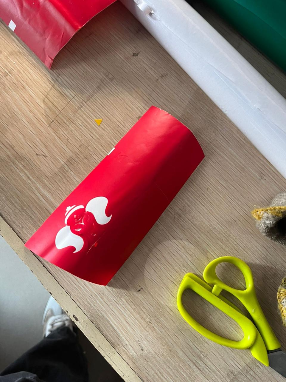 This stage shows the weeding process after vinyl cutting, where excess material is removed to reveal the final design. Through this, I understood the importance of cut depth calibration—too shallow makes peeling difficult, while too deep damages the backing. The process also required patience and precision to avoid tearing smaller features.
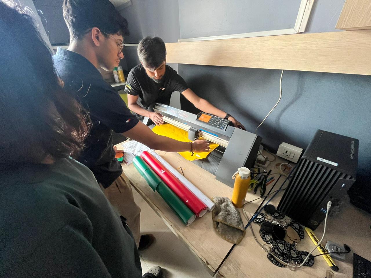
Image 4 (Vinyl cutting machine setup)
 Here, I was operating the vinyl cutter to test different materials and settings. This step was important to understand machine parameters such as speed, pressure, and blade depth. It also helped in learning proper material placement and alignment to avoid skewed cuts. This experimentation ensured better control over output quality.
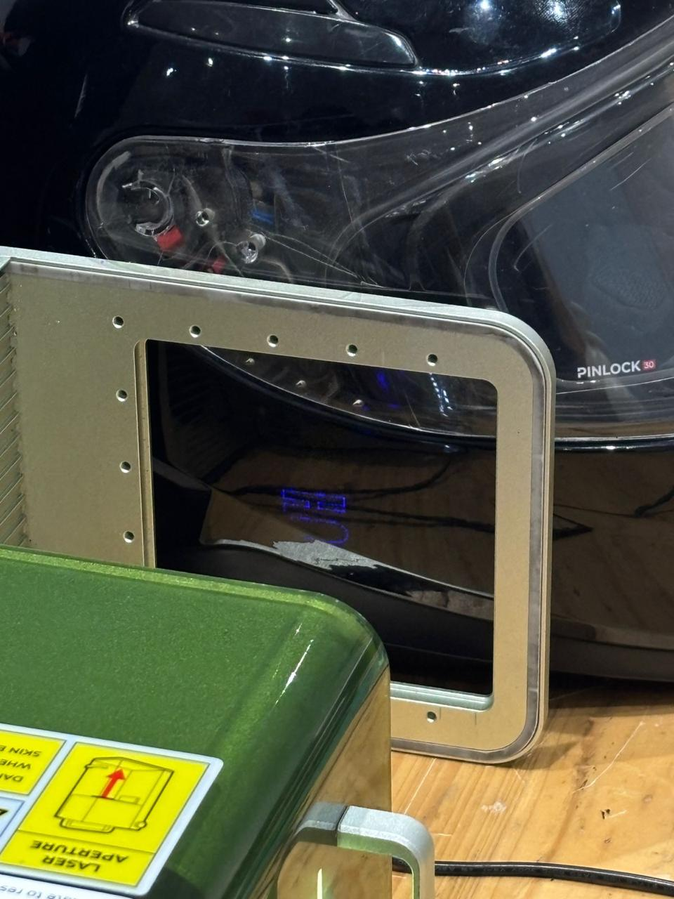 In this experiment, I used the xTool F1 laser engraver to explore working on a non-planar surface, specifically a motorcycle helmet. Unlike flat materials, the curved geometry introduced challenges in maintaining consistent focal distance across the surface, which directly affects engraving sharpness and depth. I utilized the built-in camera preview system to approximately position the design, understanding its limitation in accurately mapping curved surfaces. Multiple focus adjustments were required to identify the optimal working height, but variation across the surface still resulted in uneven energy distribution. This helped me understand how galvo-based laser systems behave on complex geometries and why they are primarily optimized for flat substrates. The process also highlighted the importance of surface alignment, fixturing, and potential need for rotary or 3D mapping systems for accurate results. Overall, this experiment provided insight into the constraints of laser engraving on curved objects and informed future decisions for material and process selection.
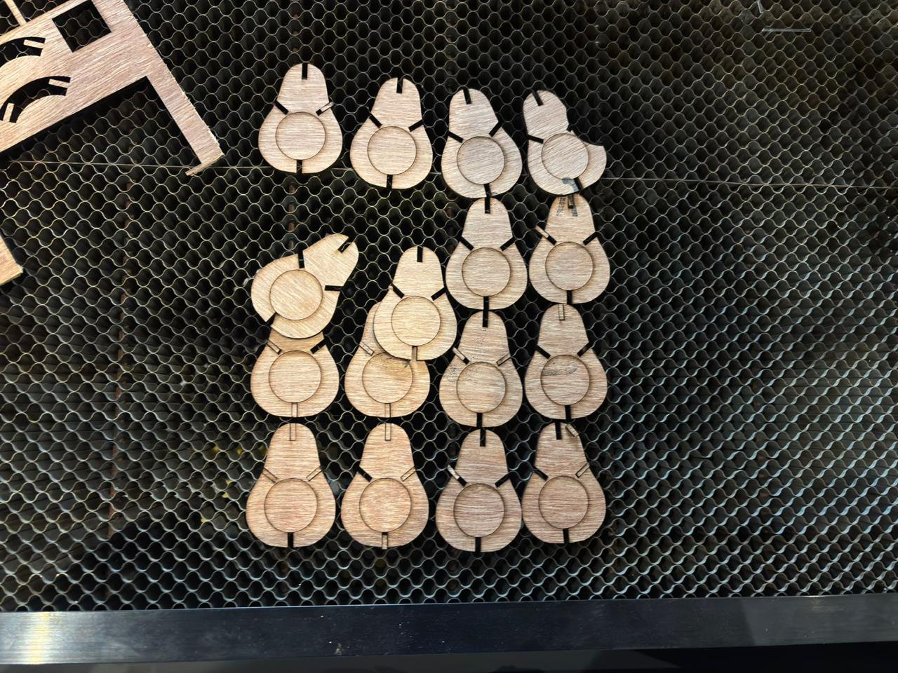 After laser cutting, I produced multiple iterations of the same component to test fit and tolerances. This step was crucial to refine slot dimensions for press-fit assembly. It showed how even small variations in kerf can affect the tightness of joints and overall stability of the structure.
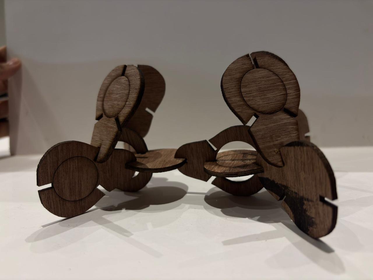 In this exploration, I assembled the laser-cut parts into a three-dimensional form. The goal was to test how flat components can create volume through interlocking. This helped me understand balance, structural stability, and how slot orientation influences the final form.
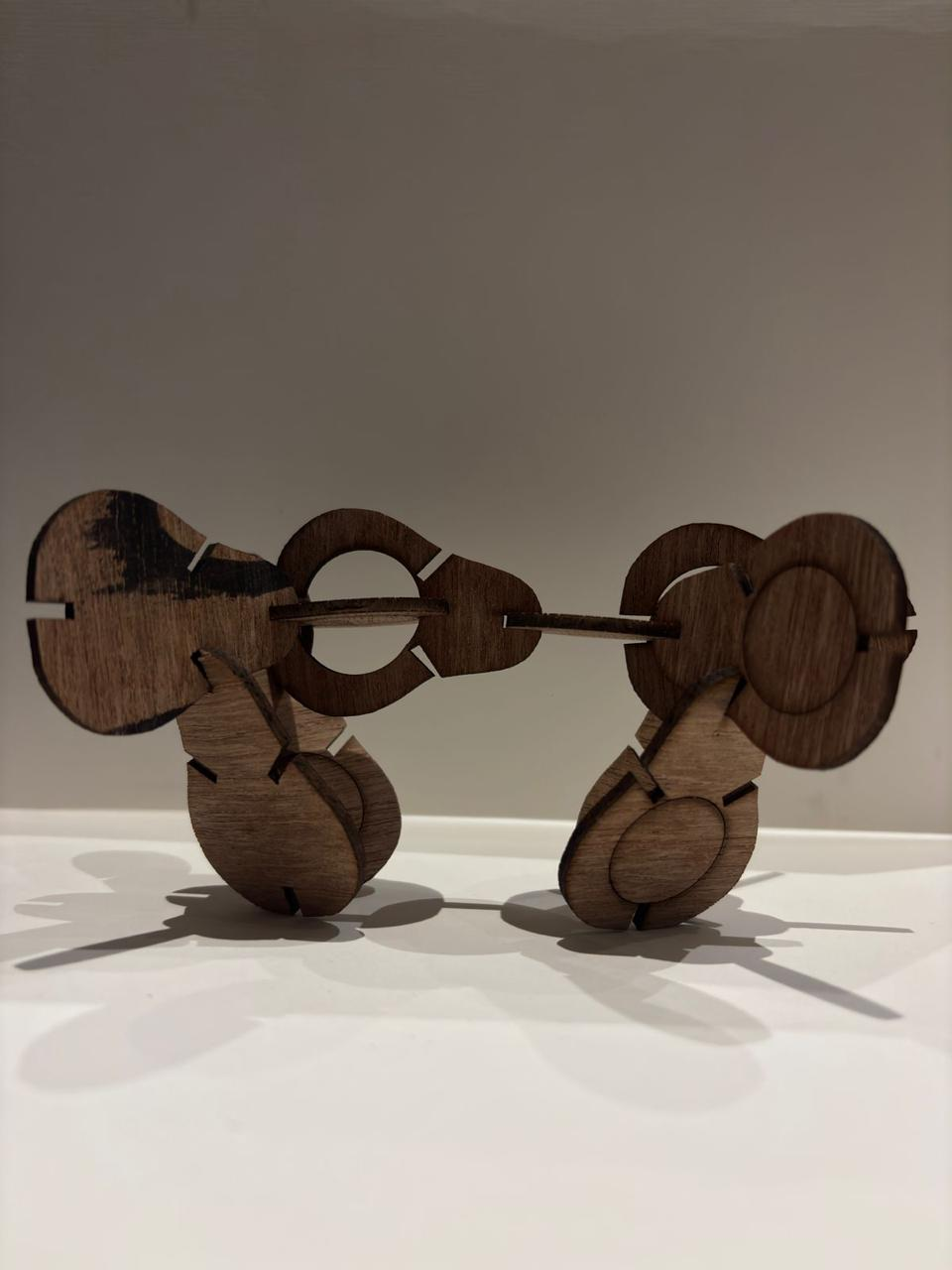 This iteration focuses on symmetry and connectivity between two modular units. I experimented with linking multiple components using a central axis, which introduced the idea of movement or interaction between forms. It also highlighted alignment challenges during assembly.
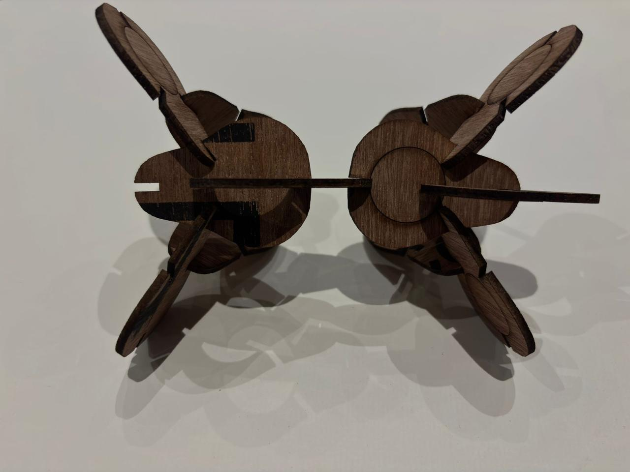 The top view helped analyze the structural logic and connection points more clearly. It revealed how forces and balance are distributed across the assembly. This perspective was useful to evaluate whether the design could sustain itself without external support.
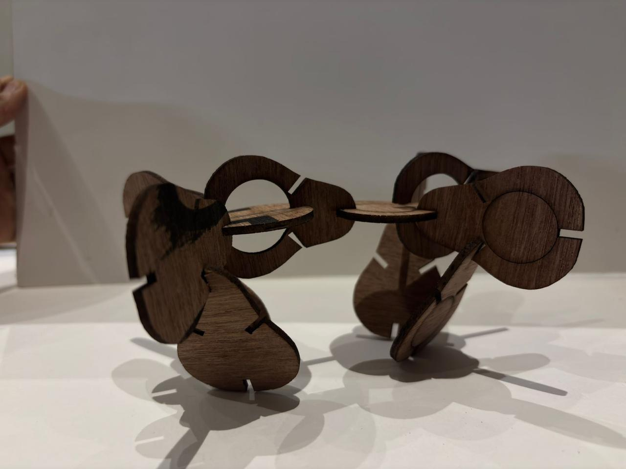 In this stage, I explored how the structure behaves when oriented differently. The focus was on testing stability and understanding the center of gravity. This helped identify weak joints and areas where additional support or redesign was needed.
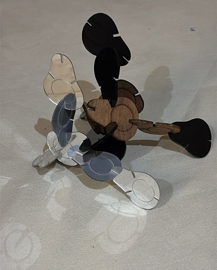
I designed a single organic, avocado-shaped profile and incorporated slots based on the material thickness to enable friction-based assembly without using any glue or external fasteners. The design was cut using both acrylic and plywood, allowing me to observe differences in material behavior such as rigidity, flexibility, and visual transparency. After fabrication, I experimented with multiple orientations and connections of the same module to understand how a 2D shape can be transformed into a 3D structure through iterative assembly. The final form is an outcome of this exploration, resulting in an organic and clustered composition rather than a predefined object. Through this process, I gained a better understanding of kerf, tolerance, and the importance of precise slot dimensions for achieving a proper press-fit, along with insights into how modular systems can be developed from simple repeated geometries.