Week 7 Computer Controlled Machining
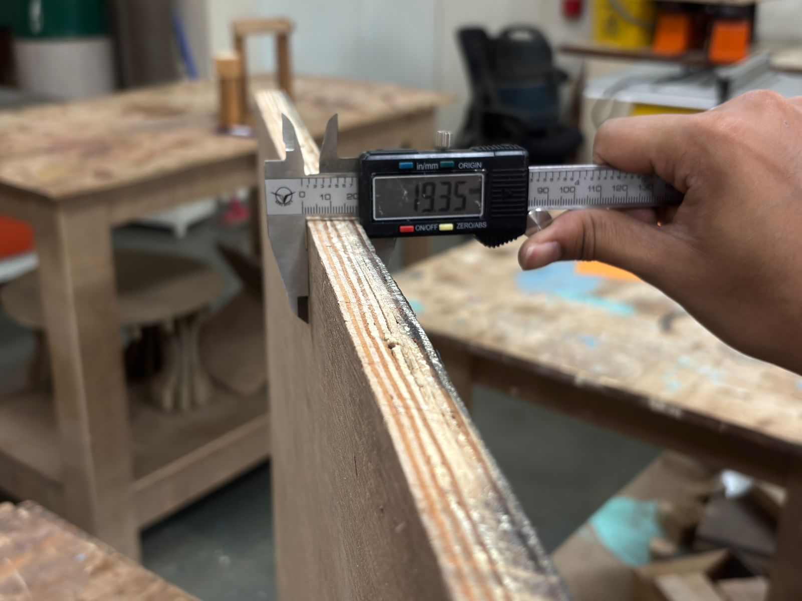
1 Measuring the Plywood Thickness
Before starting the machining process, the plywood sheet thickness was measured using a digital vernier caliper to ensure accurate cutting parameters. The measured thickness was approximately 19.35 mm, which helped in deciding the tool depth and cutting strategy. This step was important to avoid overcutting or incomplete engraving during CNC machining. Accurate material measurement also ensured proper fitting and consistency in the final output.
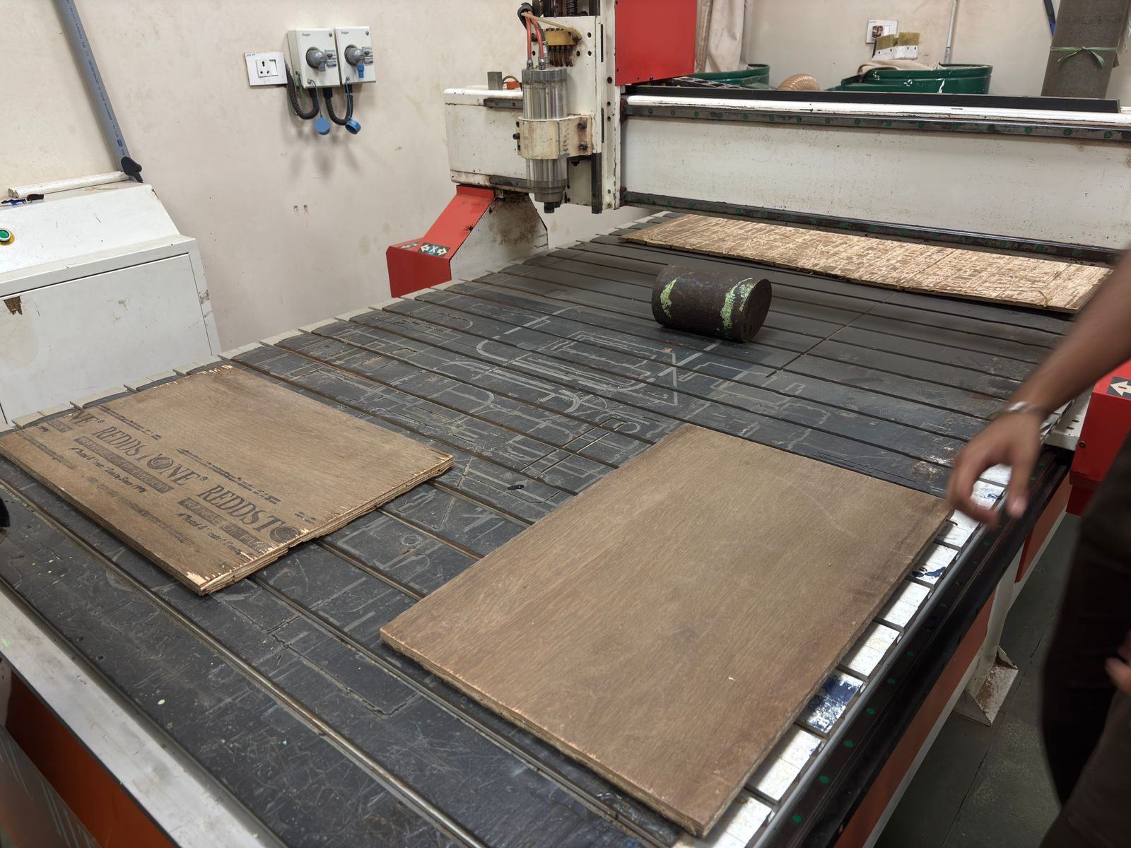
2 Preparing the CNC Bed
The plywood sheets were arranged properly on the CNC router bed before machining. Positioning the material correctly is essential to maximize workspace utilization and maintain alignment during the cutting process. The surface was checked for flatness to prevent uneven cuts and vibration while machining. Proper setup at this stage reduces errors later in the workflow.
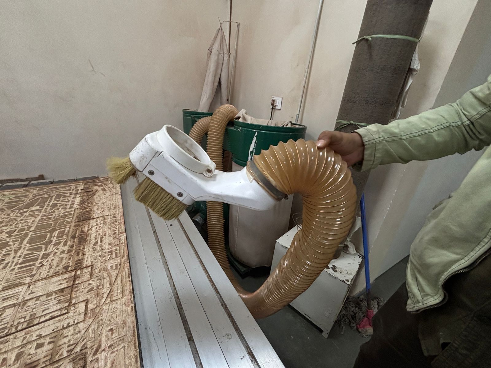
3 Dust Collection System Setup
The CNC machine was equipped with a dust collection system connected through a flexible vacuum hose. This setup helps in continuously removing wood dust and debris generated during cutting and engraving. Maintaining a clean workspace improves visibility of the machining process and increases safety. It also prevents dust accumulation around the spindle and moving components.
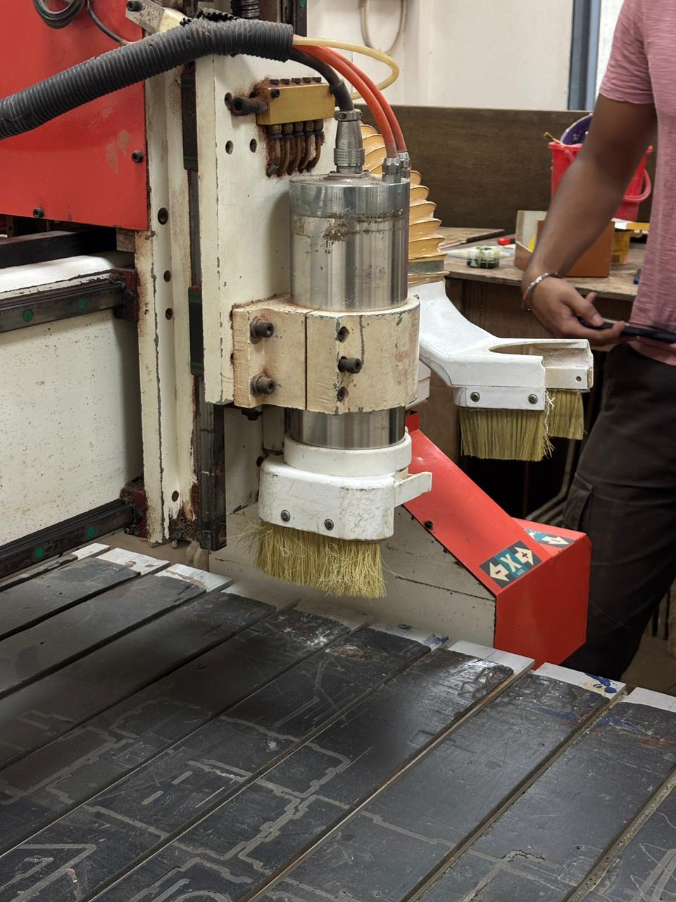
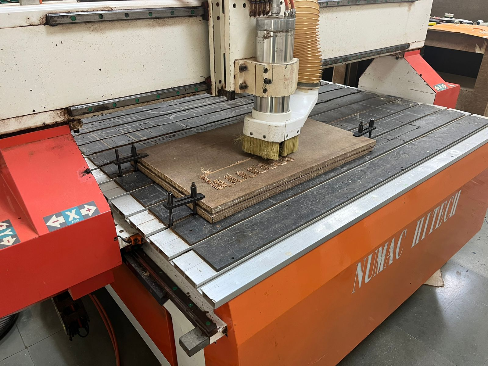
4 CNC Spindle and Dust Brush Assembly
The spindle assembly of the CNC machine contains the cutting tool used for engraving and milling operations. Around the spindle, a dust brush attachment helps contain and direct debris toward the vacuum extraction system during machining. This combination improves machining cleanliness and protects the operator from airborne particles. The spindle setup also ensures stable and precise tool movement.
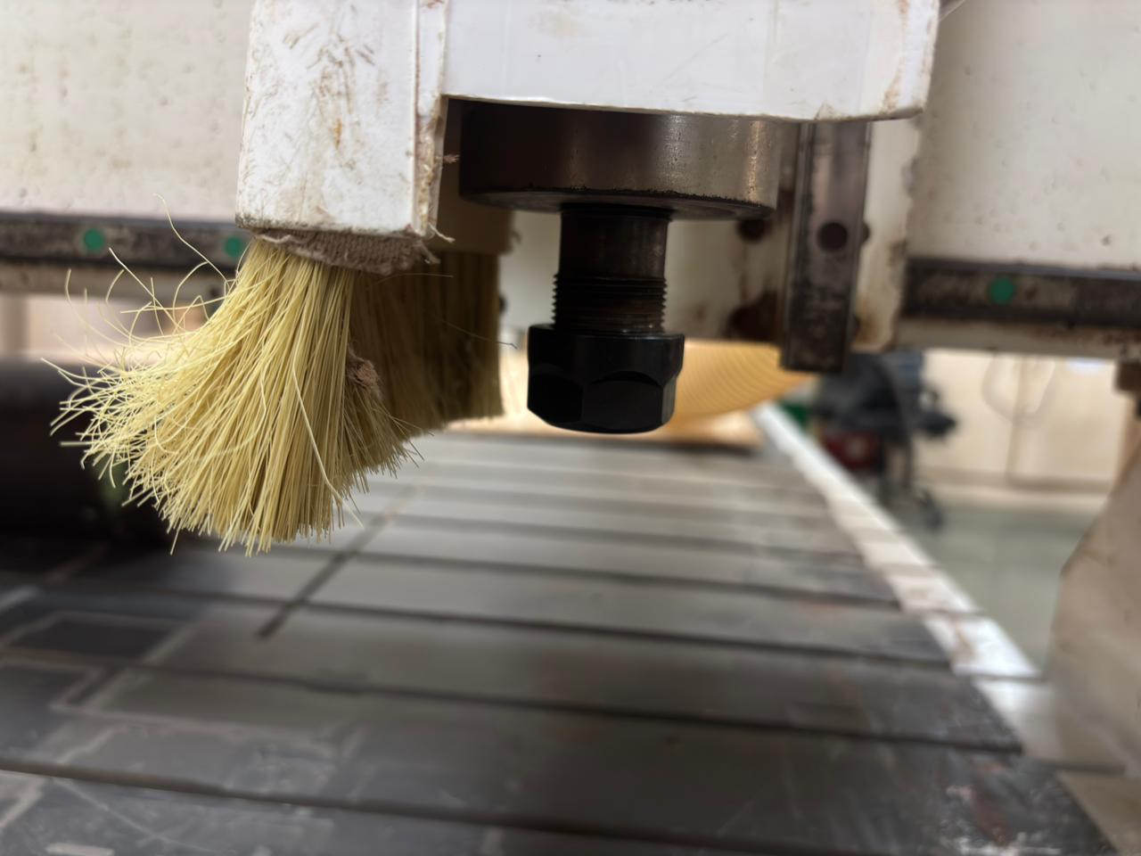
5 Collet and Tool Holding Mechanism
The cutting tool is mounted securely inside the spindle using a collet nut mechanism. This component is critical because it firmly holds the milling bit during high-speed rotation. A properly tightened collet reduces vibration and improves machining accuracy. Incorrect tool holding could lead to poor surface finish or tool slippage during operation.
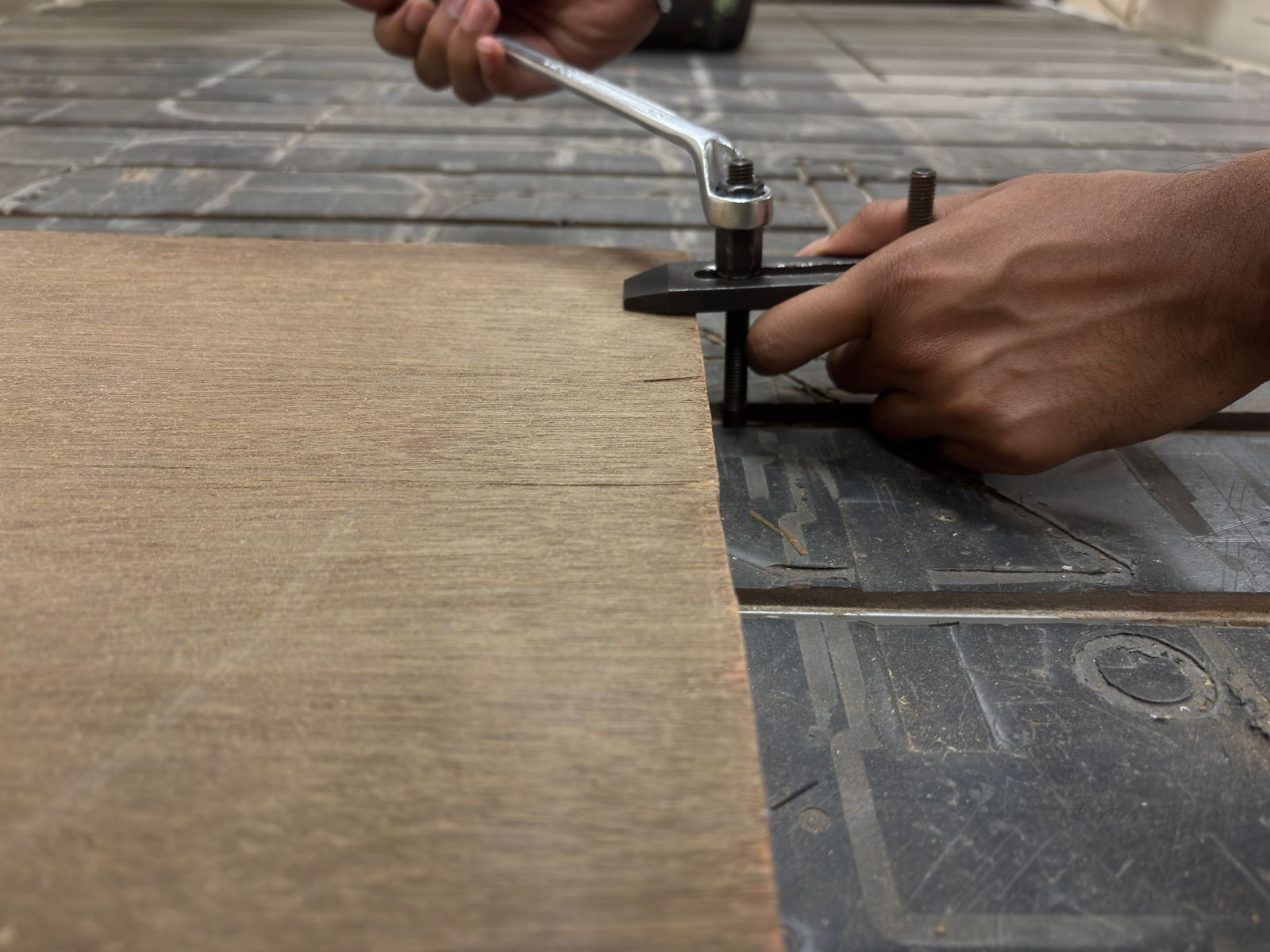
6 Securing the Material on the CNC Bed
Clamps were used to firmly hold the plywood sheet onto the CNC machine bed before machining began. Proper clamping prevents material movement caused by cutting forces and spindle vibration. The positioning of clamps was carefully planned to avoid collision with the toolpath. Stable material fixation is essential for precise and safe CNC operation.
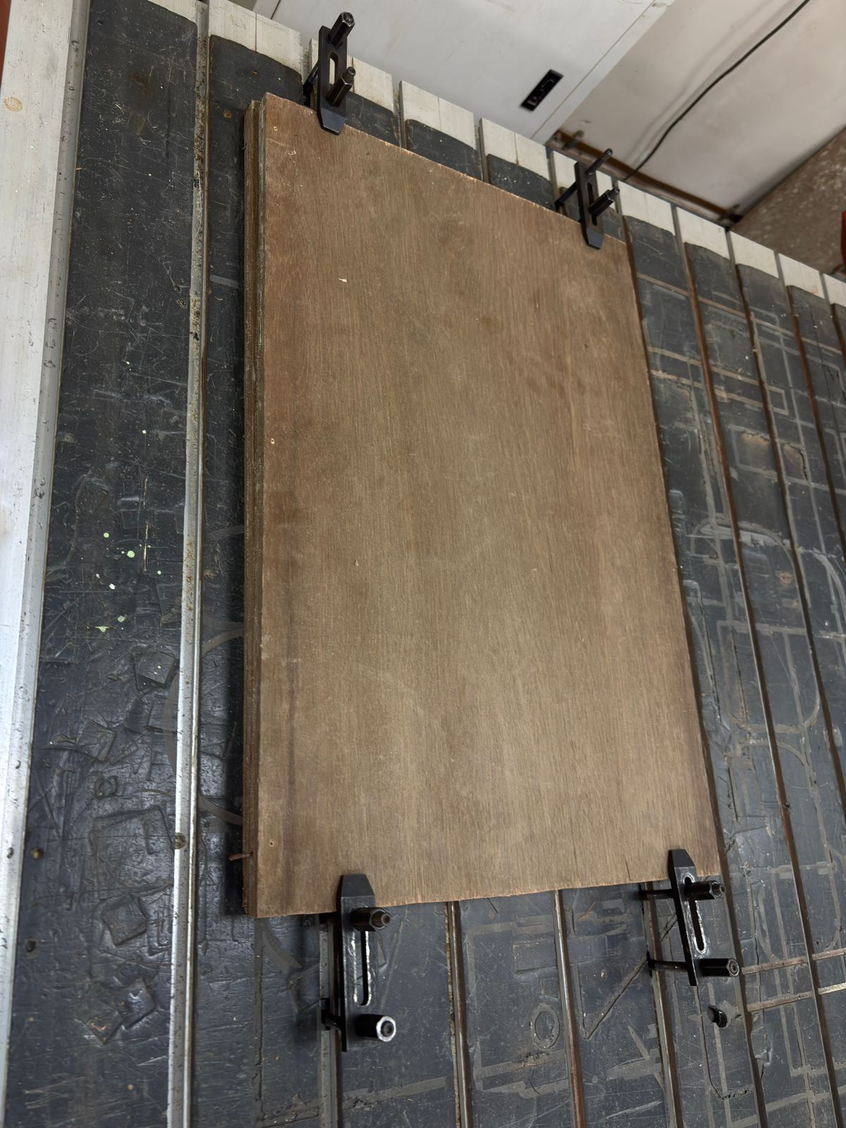
7 Final Material Positioning
After clamping, the plywood sheet was checked again to ensure it remained flat and properly aligned with the machine axes. Correct positioning is important for maintaining dimensional accuracy throughout the machining process. The setup stage also included verifying that sufficient clearance existed around the workpiece for tool movement. This prepared the material for accurate engraving and cutting.
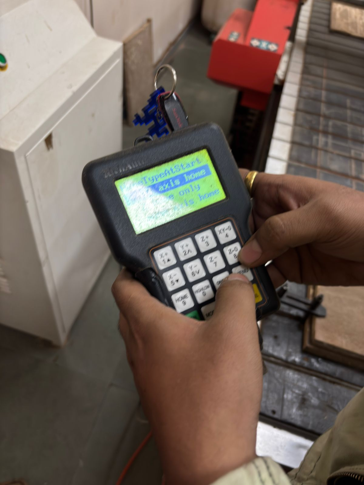
8 Setting the Machine Origin
The machine origin and axis positions were configured using the CNC controller interface before starting the machining process. Defining the correct home position allows the CNC machine to interpret the toolpath accurately. This step ensures the design is engraved in the intended location on the material surface. Proper origin setup is one of the most critical stages before running the final job.
9 Beginning the Machining Process
Once the origin and tool settings were verified, the CNC machine began engraving the design onto the plywood surface. The spindle moved according to the programmed toolpath while removing material layer by layer. During this stage, the cutting parameters such as spindle speed and feed rate played an important role in surface quality. Continuous monitoring was done to ensure smooth machining.
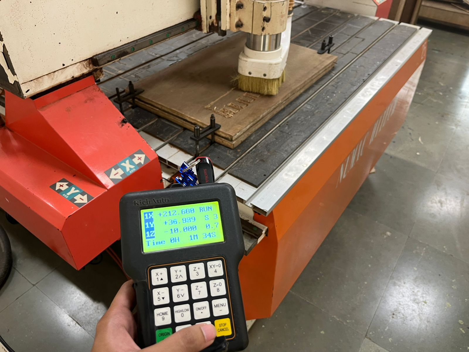
10 CNC Engraving in Progress
The CNC router continued carving the design with controlled and repeatable movements. The dust extraction system operated simultaneously to keep the machining area clean and visible. The engraved regions gradually revealed the final pattern on the plywood surface. This stage demonstrated the precision and automation capability of the CNC machining workflow.
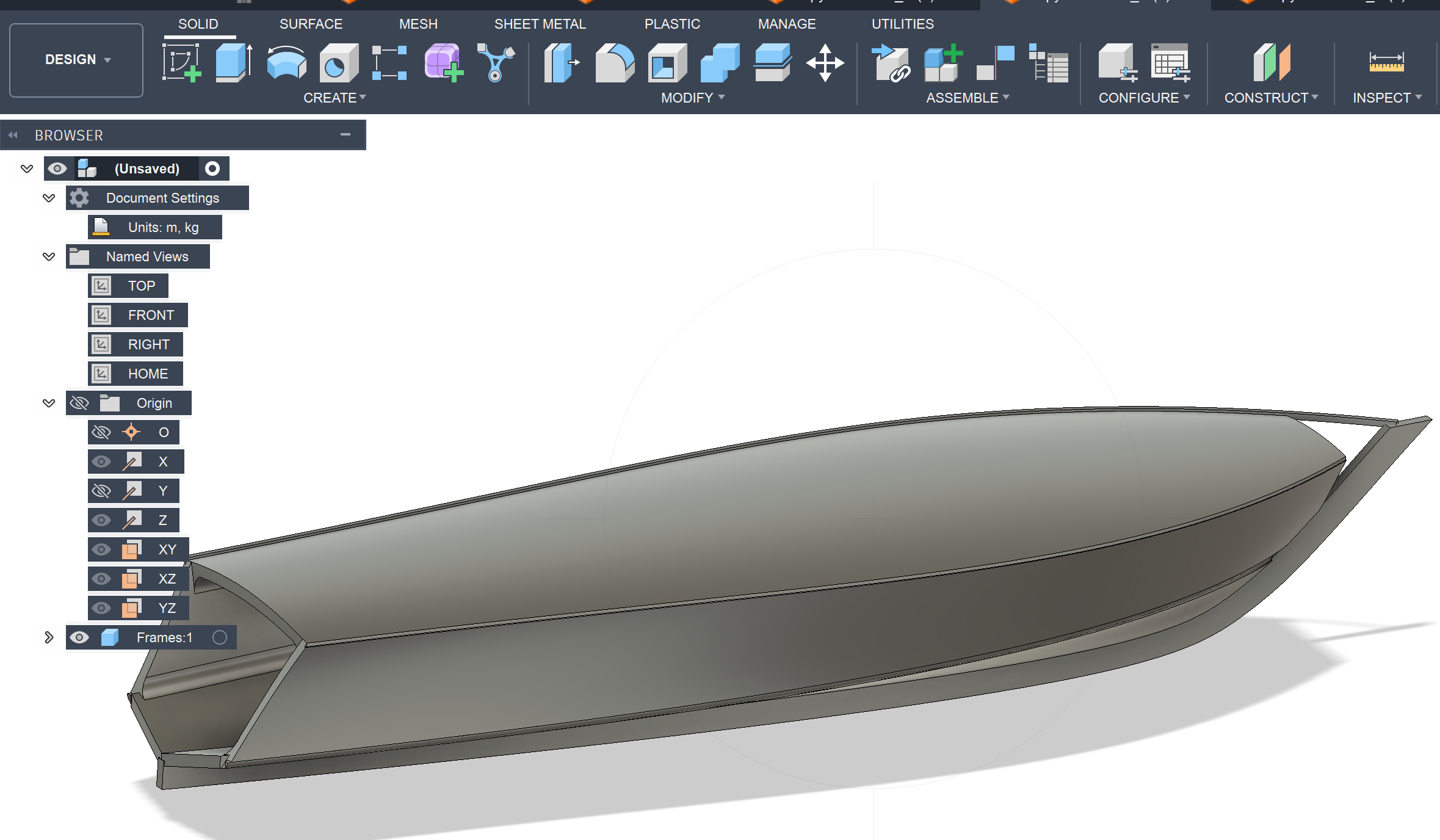
11 Initial Boat Hull Surface Design
The initial boat hull form was modeled in Fusion 360 to explore the outer geometry and proportions of the structure. Basic surfaces and side profiles were created to understand the overall shape and curvature of the boat. This stage focused mainly on form development rather than fabrication constraints. The model provided a starting point for further structural refinement.
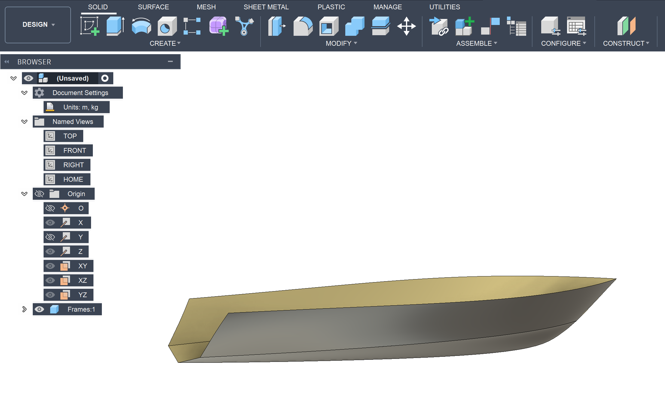
12 Refined Hull Geometry Development
The hull geometry was further refined by improving the smoothness and continuity of the surfaces. The updated design achieved a cleaner aerodynamic and hydrodynamic form while maintaining structural balance. Additional edge profiles and transitions were adjusted to create a more realistic boat structure. This helped in improving both appearance and manufacturability.
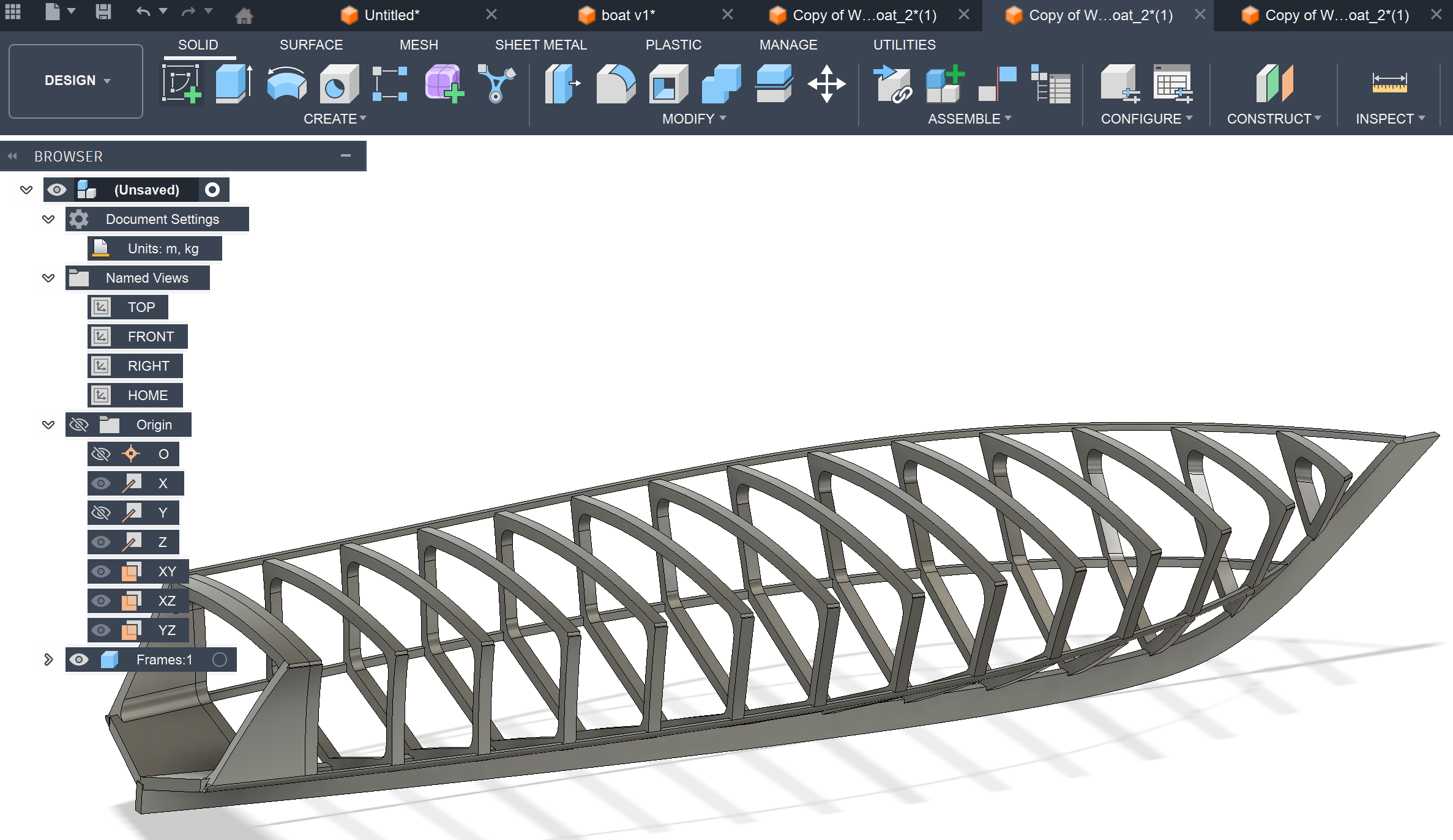
13 Internal Rib Structure Creation
After finalizing the outer form, internal ribs were added to create the structural framework of the boat. These ribs act as support members that maintain the shape and rigidity of the hull. The rib spacing was designed uniformly to distribute load and reduce deformation. This stage transformed the design from a surface model into a fabrication-oriented structure.
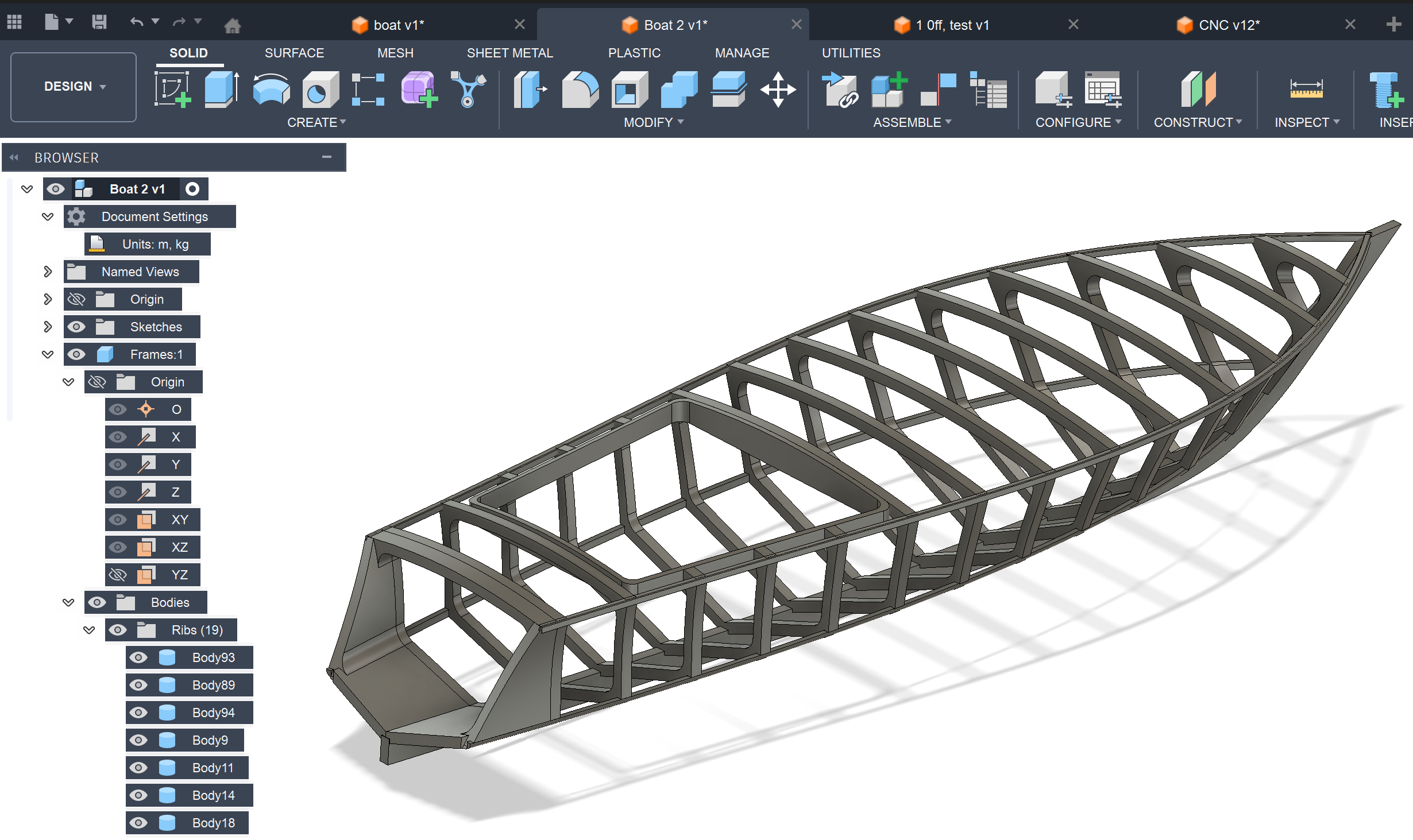
14 Design Optimization for Material Reduction
During further iterations, the boat structure was redesigned to reduce unnecessary material usage and simplify manufacturing. Certain sections of the original model were modified to create a lighter and more efficient framework. The updated rib arrangement improved structural efficiency while minimizing waste during CNC cutting. This optimization made the design more suitable for fabrication.
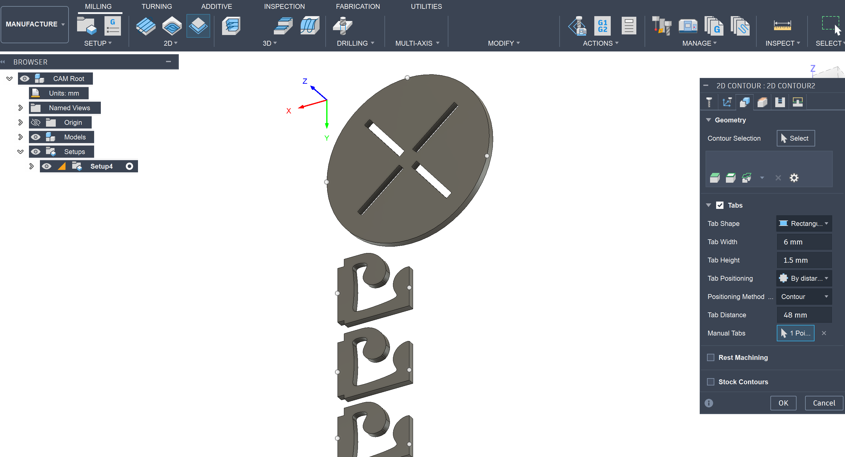
15 Creating CNC Machining Toolpaths
The optimized components were imported into the Manufacturing workspace in Fusion 360 for CNC preparation. Contour operations and tabs were added to ensure the parts remained fixed during machining. Toolpaths were configured carefully to maintain dimensional accuracy and clean edge quality. This step converted the CAD geometry into machinable operations.
16 Defining CNC Setup and Work Coordinates
The machining setup was configured by defining the stock size, work coordinate system, and machining origin. Correct axis orientation and stock positioning are essential for accurate CNC operation. The setup also ensured that all components fit properly within the available material dimensions. This stage established the reference system required for machining.

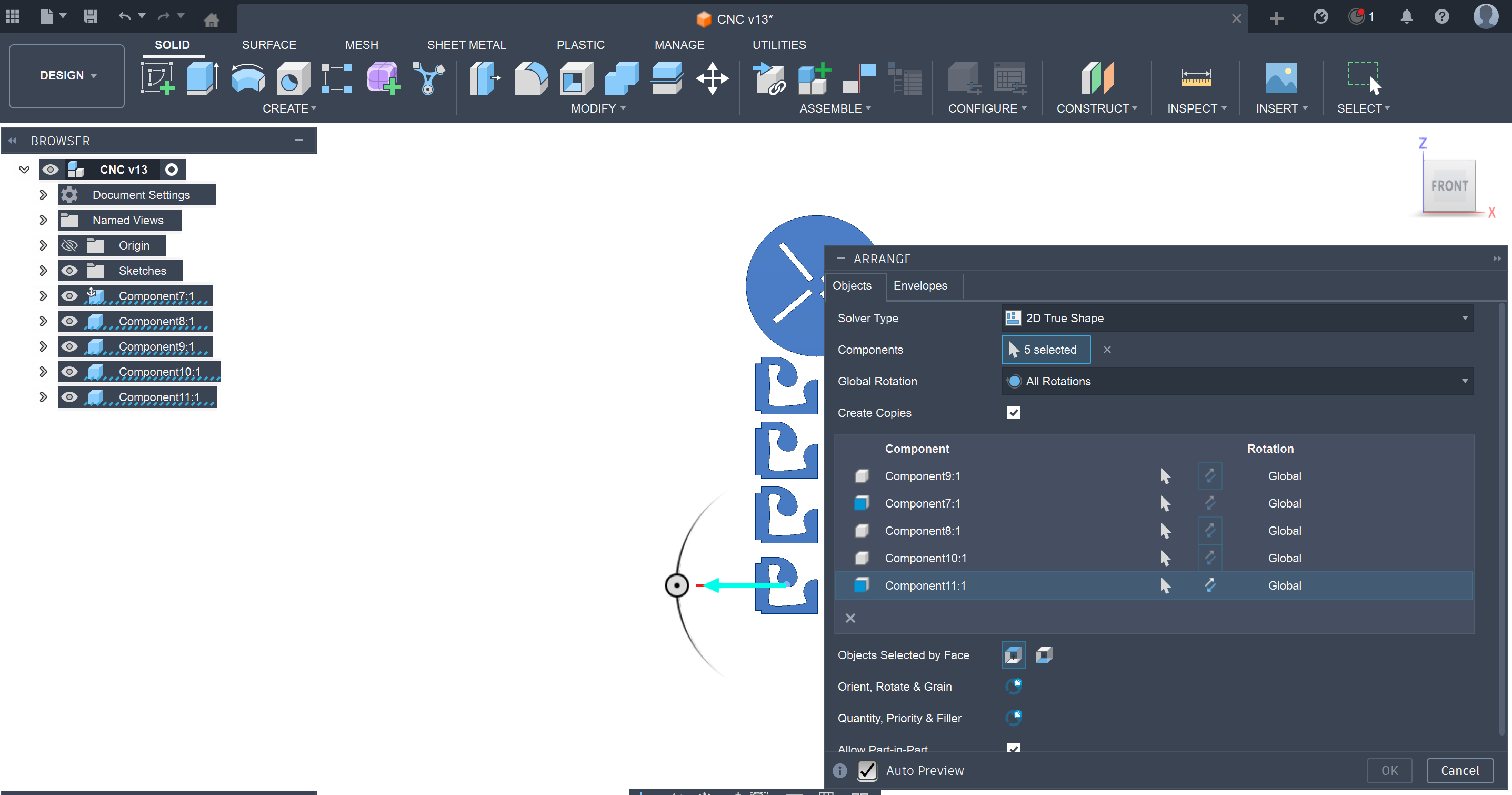
17 Arranging Components for Sheet Optimization
The individual boat components were arranged efficiently on the virtual material sheet using the Arrange feature in Fusion 360. This nesting process helped reduce unused space and improve material utilization. Different orientations were tested to achieve a compact layout while maintaining machining clearance. Proper arrangement directly contributes to reducing production cost and material waste.
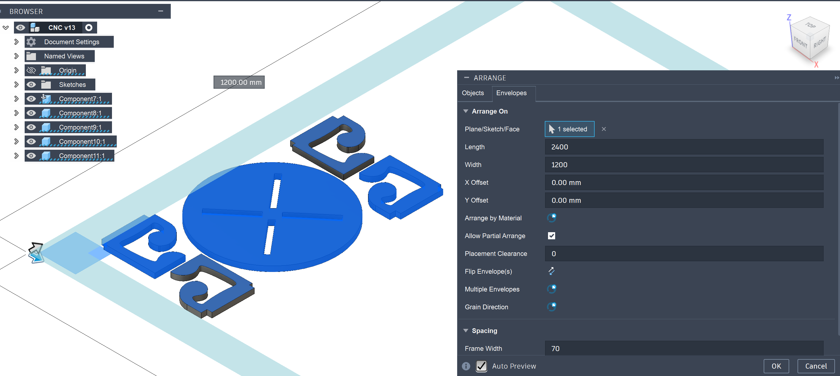
18 Final Nesting Layout Preparation
The optimized arrangement of components was finalized within the defined sheet dimensions. Adequate spacing was maintained between parts to avoid tool collision and ensure safe cutting operations. The layout was checked for manufacturability before generating final machining toolpaths. This stage prepared the complete design for CNC fabrication.
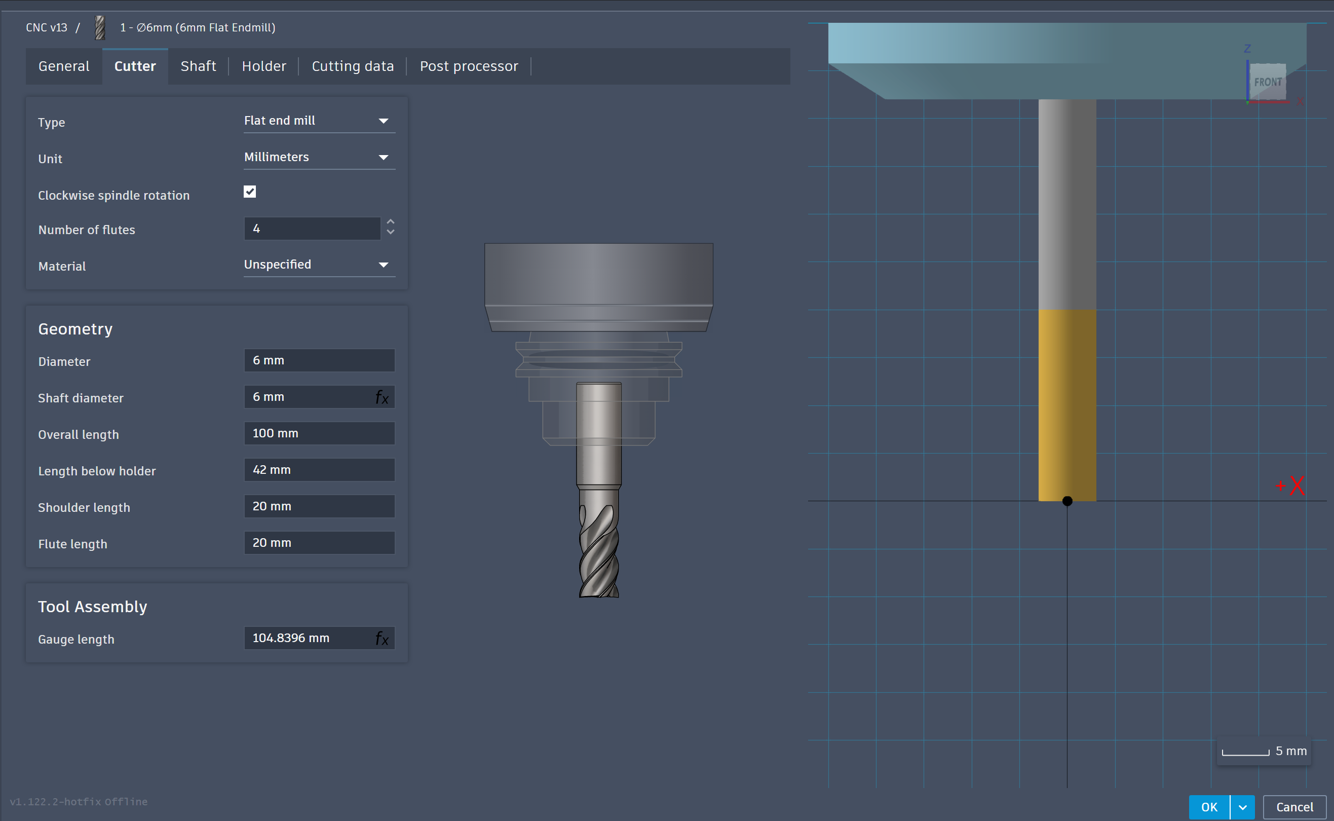
19 Selecting the CNC Cutting Tool
An appropriate flat end mill cutter was selected from the Fusion 360 tool library for machining the plywood components. Tool parameters such as diameter, flute length, and spindle settings were reviewed before machining. Selecting the correct cutting tool is critical for achieving clean edges and accurate cuts. The chosen tool was suitable for plywood milling operations.
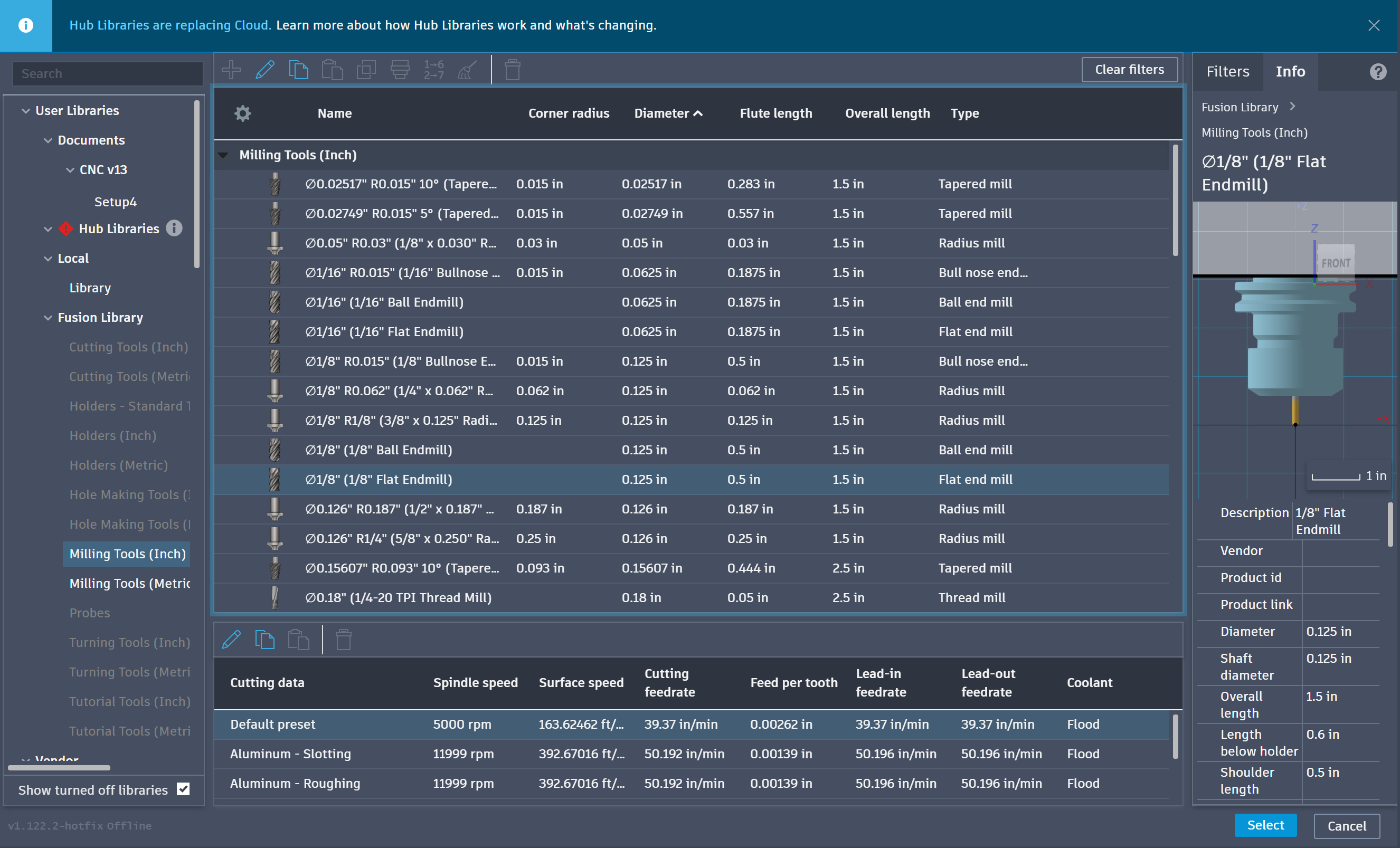
20 Configuring Tool Geometry Parameters
Detailed cutter settings including diameter, flute length, shaft dimensions, and tool assembly parameters were configured in Fusion 360. These values help simulate accurate machining behavior and prevent tool collisions during operation. Proper tool definition also improves toolpath accuracy and machining reliability. This finalized the CNC preparation process before generating the G-code.