1️⃣ Initial Observations – Understanding Embedded Systems in the Lab
At the beginning of the week, I observed different embedded system projects in the lab:
A smoke sensor system that detects gas/smoke levels and triggers alerts.
A line-following robot that recognizes a black line on the floor using sensors and adjusts its movement accordingly.
And most interestingly, I was inspired by Thing, the disembodied hand from Wednesday.
Seeing these systems helped me understand one important thing:
Embedded systems are not just circuits. They are decision-making systems.
2️⃣ Each of them followed a pattern:
Sense something
Process it
Act accordingly
That became the foundation of my own experiment.
3️⃣ Concept – Building a Reactive Walking Robot
 Inspired by the hand from Wednesday, I decided to attempt a small robotic creature that:
Uses servo motors as legs
Uses an ultrasonic sensor as input
Moves forward or backward depending on distance
Behaves like a reactive system
Hardware Used
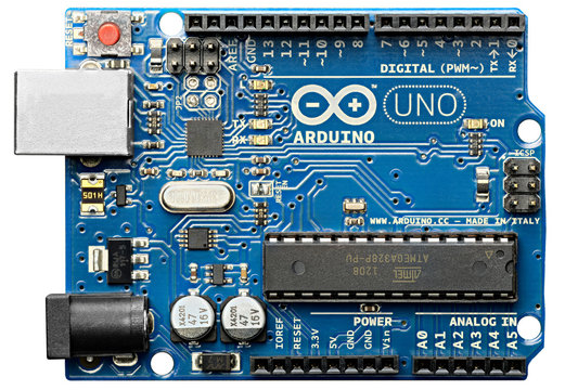
Arduino Uno
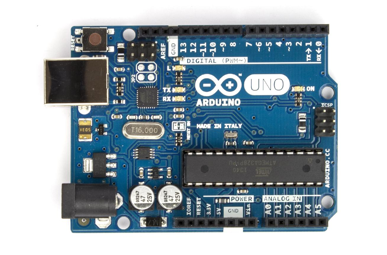 The Arduino Uno acts as the brain of the system, processing input from the ultrasonic sensor and controlling the servo motors accordingly. It reads the distance data, converts it into meaningful values, and maps it to servo angles. This enables real-time interaction between the user’s hand and the mechanical hand. It also provides the required PWM signals to drive multiple servos. Overall, it coordinates sensing, computation, and actuation in the project
4 Servo motors
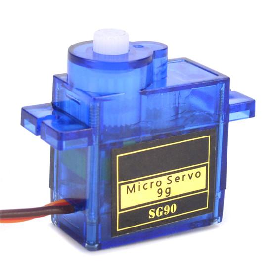 Servo motors act as the output devices that physically move the fingers of the hand. They rotate to specific angles based on the signal received from the Arduino. By mapping distance to angle, the servos open or close the fingers to mimic hand gestures. Each servo can represent one finger or joint for more realistic movement. Their precise control makes them ideal for creating smooth and responsive motion.
Ultrasonic sensor (HC-SR04) The ultrasonic sensor is the input device that detects the distance of a hand placed in front of it. It emits ultrasonic sound waves and measures the time taken for the echo to return after hitting an object. This time is converted into distance, which is used as the control parameter for the system. When the hand moves closer or farther, the sensor continuously updates the distance. This allows the mechanical hand to respond dynamically to real-world movement.
External power supply for servos
Arduino IDE for coding
include
// Ultrasonic pins
define TRIG_PIN 9
define ECHO_PIN 10
// Servo objects Servo servo1; Servo servo2; Servo servo3; Servo servo4; // optional (if you have 4 servos)
// Servo pins
define S1 3
define S2 5
define S3 6
define S4 11 // optional
long duration; float distance;
// Distance range (tune this!) float minDist = 5; // hand very close float maxDist = 30; // hand far
void setup() { pinMode(TRIG_PIN, OUTPUT); pinMode(ECHO_PIN, INPUT);
servo1.attach(S1); servo2.attach(S2); servo3.attach(S3); servo4.attach(S4);
Serial.begin(9600); }
float getDistance() { digitalWrite(TRIG_PIN, LOW); delayMicroseconds(2);
digitalWrite(TRIG_PIN, HIGH); delayMicroseconds(10); digitalWrite(TRIG_PIN, LOW);
duration = pulseIn(ECHO_PIN, HIGH); distance = duration * 0.034 / 2;
return distance; }
void loop() { float d = getDistance(); Serial.println(d);
// Constrain distance d = constrain(d, minDist, maxDist);
// Map distance → angle (invert mapping) int angle = map(d, minDist, maxDist, 180, 0);
// Apply to servos servo1.write(angle); servo2.write(angle); servo3.write(angle); servo4.write(angle);
delay(50); }
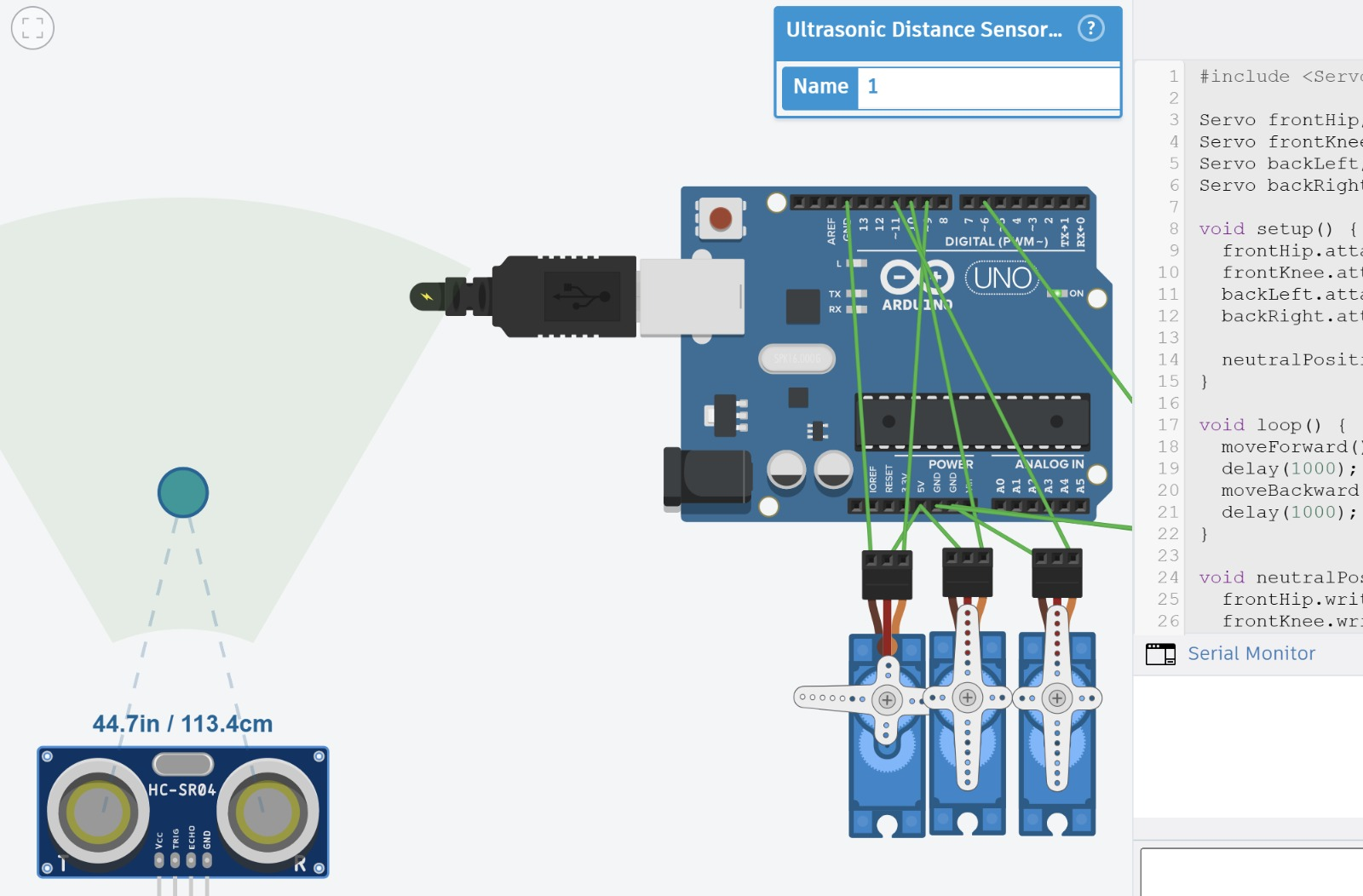
Architecture of the Robot
The idea was simple:
Input:
Ultrasonic sensor measures distance.
Processing:
Arduino checks distance condition.
Output:
If object is close → move forward.
If object is far → move backward.
The structure of logic was:
Read distance → Compare with threshold → Call movement function
I first tested:
Single servo
Then 4 servos together
Then created forward and backward movement functions
Finally integrated ultrasonic input
I learned the importance of:
Common ground between external power and Arduino
Testing movement before adding sensing
Structuring code into functions
This phase taught me about sequencing and debugging physical motion.
4️⃣ Going Deeper – Understanding the Microcontroller Itself
After working with Arduino, I became curious:
What is actually inside Arduino?
Arduino Uno uses a chip called ATmega328P. But to simplify and understand further, I explored:
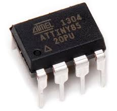
ATtiny85
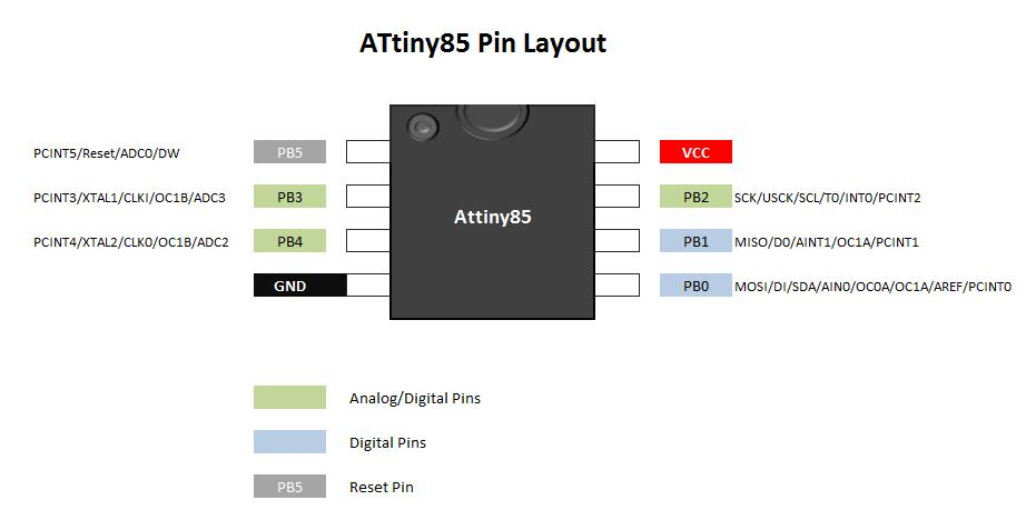 This is a small 8-pin microcontroller.
5️⃣ Understanding Core Concepts 🔹 What is a Bootloader?
A bootloader is a small program that:
Runs before your main program
Allows code to be uploaded through a programmer
Sets configuration bits (clock speed, internal settings)
For ATtiny85:
Burning bootloader mainly sets internal clock (8 MHz).
It does NOT install a USB system like Arduino.
🔹 What is a Library?
In Arduino IDE, when we write:
digitalWrite(0, HIGH);
That is not directly understood by the chip.
The IDE:
Compiles code
Converts it into machine instructions
Uploads binary to microcontroller
The chip runs pure machine code. It does not “use Arduino library” after upload.
Bootloader (ATtiny85 Context)
5 
A bootloader is the very first piece of code that runs when a microcontroller starts. In the case of an ATtiny85, you typically don’t install a USB-style bootloader like Arduino boards have. Instead, “burning the bootloader” mainly configures internal settings such as the clock source and speed (commonly 8 MHz). The images show how an external programmer (ISP) connects to the chip and writes these configurations. Think of it as setting the chip’s internal behavior before your actual program runs. Once this is done, your main code is uploaded separately and executed after startup.
Arduino Library vs Machine Code
6 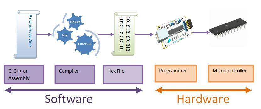
When you write something like digitalWrite(0, HIGH);, it looks simple, but the microcontroller cannot understand this directly. The images illustrate the full pipeline: your code is compiled by the Arduino IDE into machine code (binary instructions), which is then uploaded into the microcontroller’s memory. Inside the chip, only these low-level instructions are executed. The “Arduino library” exists only during development—it helps you write code faster, but after uploading, the chip is simply running raw instructions that directly control hardware registers and pins.
GPIO / PIO Concept
6 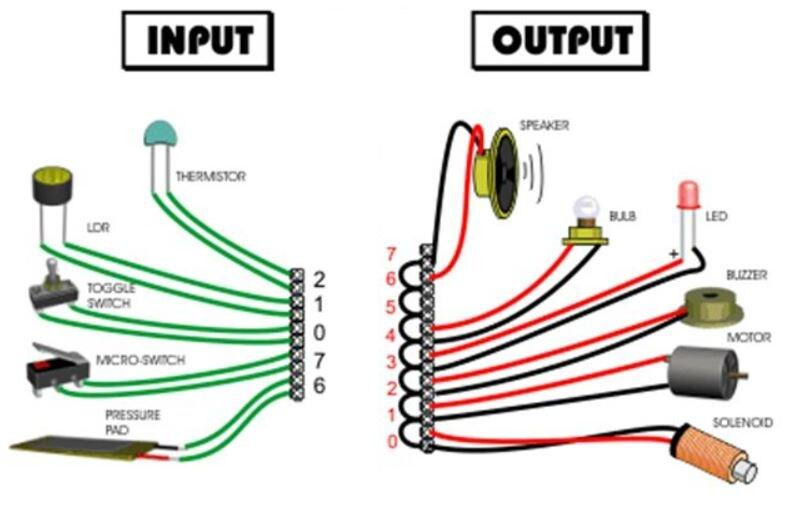
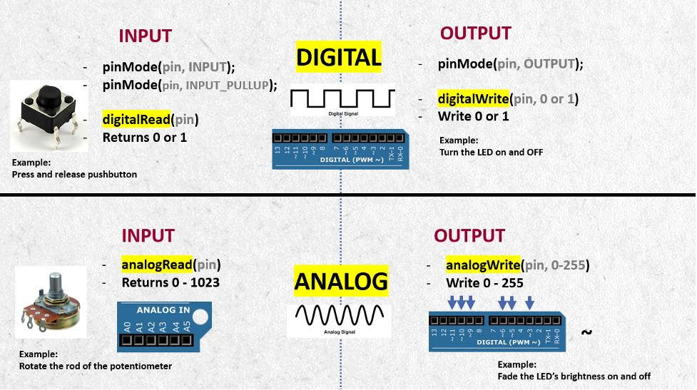
GPIO (General Purpose Input Output) pins are the interface between software and the physical world. The images show a simple flow: a button sends an input signal to the microcontroller, the program processes it, and an LED or motor responds as output. Each pin can be configured as either input or output depending on your need. This is the fundamental loop of embedded systems—reading signals, making decisions, and controlling devices. Without GPIO, the microcontroller would not be able to interact with anything outside itself.
SMD vs Through-Hole Components
6 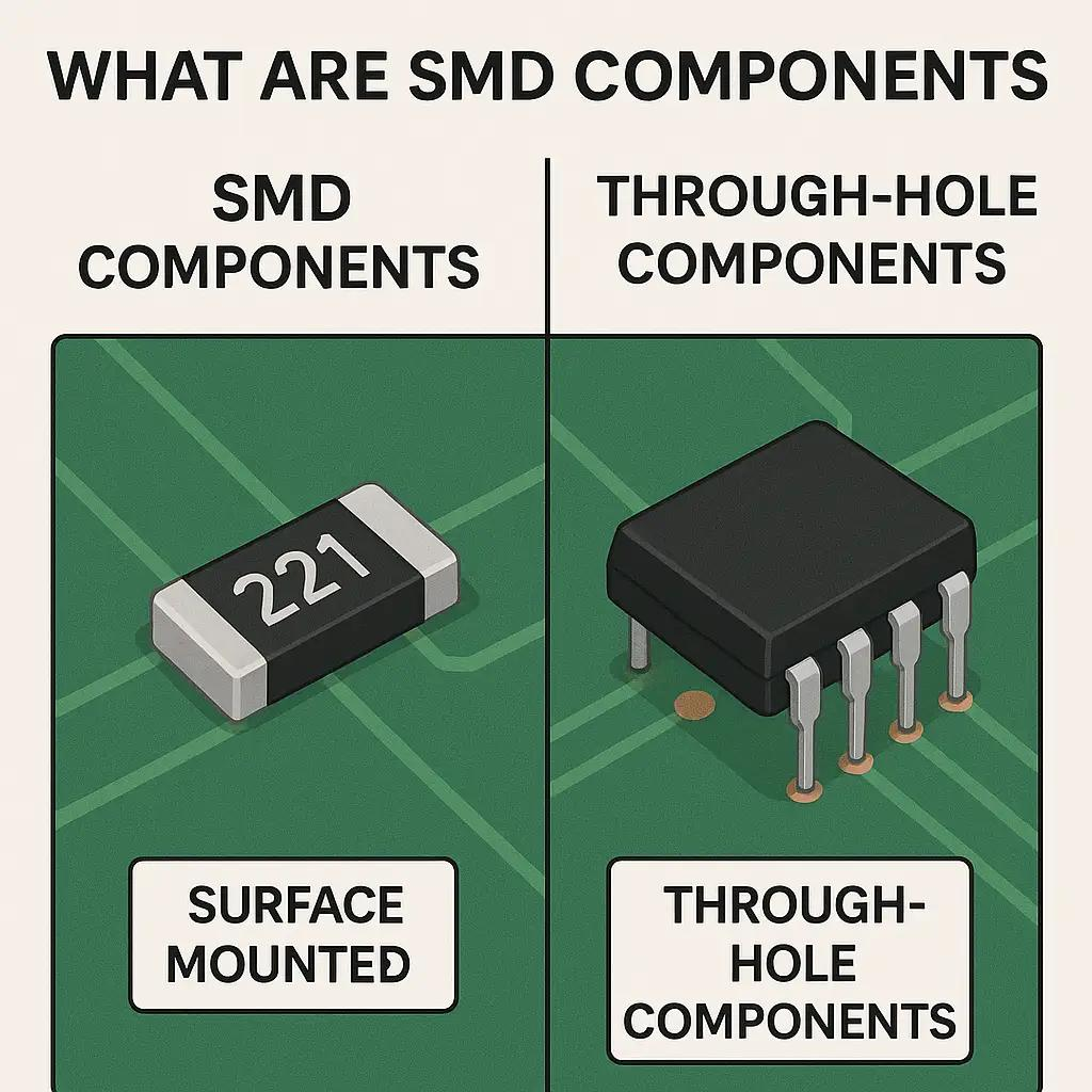
Electronic components come in two main mounting styles. Through-hole components have long leads that pass through holes in the PCB, making them easier to handle and solder, especially for beginners. SMD (Surface Mount Devices), on the other hand, sit directly on the surface of the board and are much smaller. The images highlight how compact SMD designs are compared to through-hole ones. While SMD allows for dense and modern circuit designs, it requires more precision during soldering and assembly.
LED Polarity
7 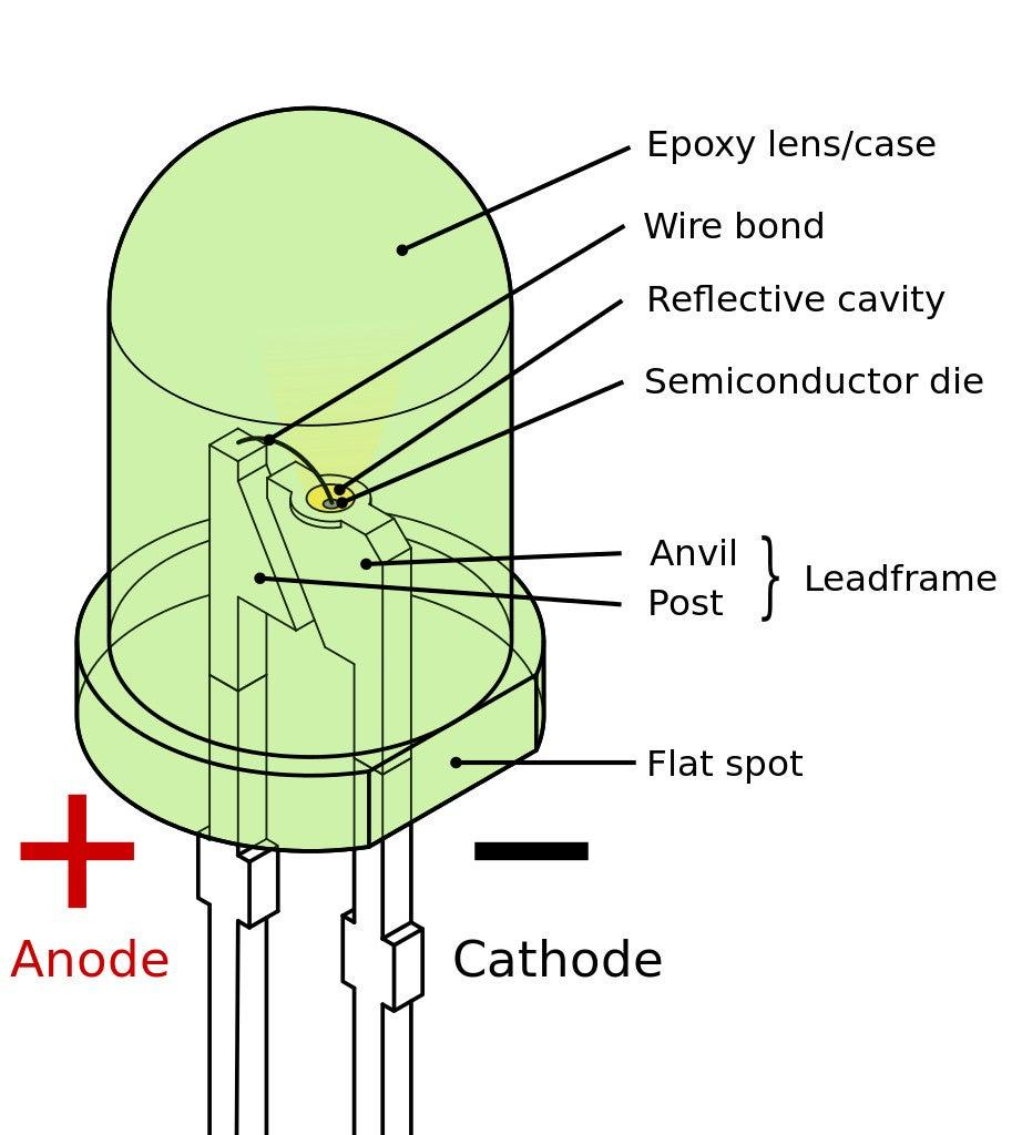
An LED only works when connected in the correct direction. The longer leg is the positive side (anode), and the shorter leg is the negative side (cathode). Inside the LED, the larger metal plate usually indicates the cathode. The images help you identify these features visually. If the polarity is reversed, current cannot flow properly and the LED will not light up. This simple concept is critical because many electronic components depend on correct orientation to function.
Diode (One-Way Current Flow)
6 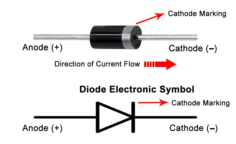
A diode is a component that allows current to flow in only one direction. The images show the arrow-like symbol that represents this behavior and how a physical diode has a stripe marking the cathode side. This property is used in circuits to protect components from reverse polarity and to convert AC to DC in rectification circuits. You can think of a diode as a one-way valve for electricity.
PCB Orientation & Markings
6 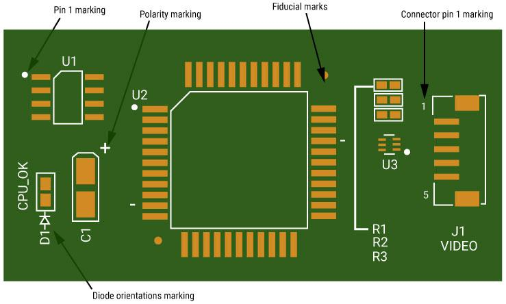
PCBs are designed with visual guides to help place components correctly. The images show the green solder mask layer, white silkscreen labels, and outlines indicating where each component should go. You can also see polarity markings and pin 1 indicators for ICs. These markings are crucial because placing a component in the wrong orientation—especially ICs or polarized parts—can prevent the circuit from working or even damage it.
CRO (Oscilloscope) & Signal Debugging
6 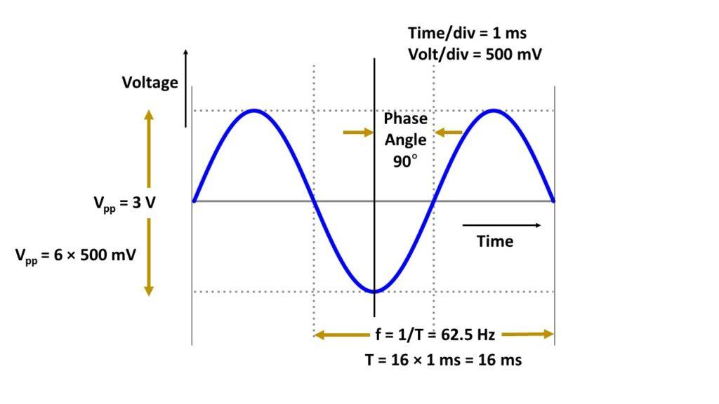
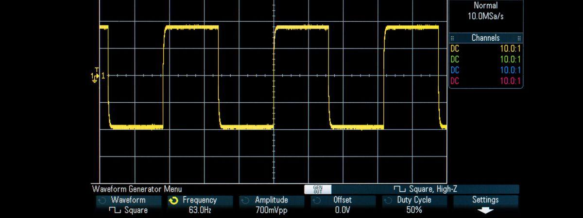 A CRO (oscilloscope) allows you to see how voltage changes over time, which is essential for understanding real signals in embedded systems. The images display waveforms such as square waves and PWM signals. Instead of guessing what your code is doing, you can visually confirm whether signals are stable, timed correctly, or distorted. This shifts debugging from just reading code to actually observing electrical behavior, which is a more accurate way to diagnose problems.
Embedded System Flow (Core Learning)
8 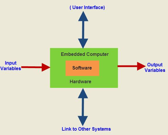
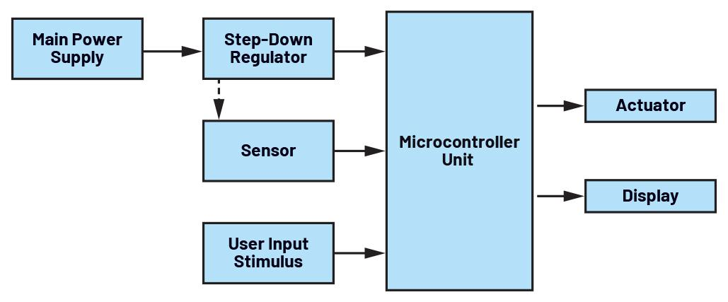
At its core, every embedded system follows a simple structure: input, processing, and output. The images represent this flow clearly. A sensor provides input, the microcontroller processes it using logic and timing, and then an output device like a motor or LED responds. This also connects to a deeper understanding—everything in embedded systems is ultimately about controlling electrical signals over time to produce meaningful physical actions.
Final Reflection (Conceptual Transition)
5 
These visuals represent the shift from seeing embedded systems as a “black box” to understanding how they actually work internally. Initially, tools like Arduino hide complexity, but as you go deeper, you begin to see the layers—electricity, timing, logic, and finally physical movement. This transition is important because it changes how you approach problems: instead of trial and error, you start reasoning through the system step by step, making debugging and design much more structured and reliable.