Week 5 3D Scanning and Printing
Understanding the 3D Scanning Device
— EinScan Pro HD
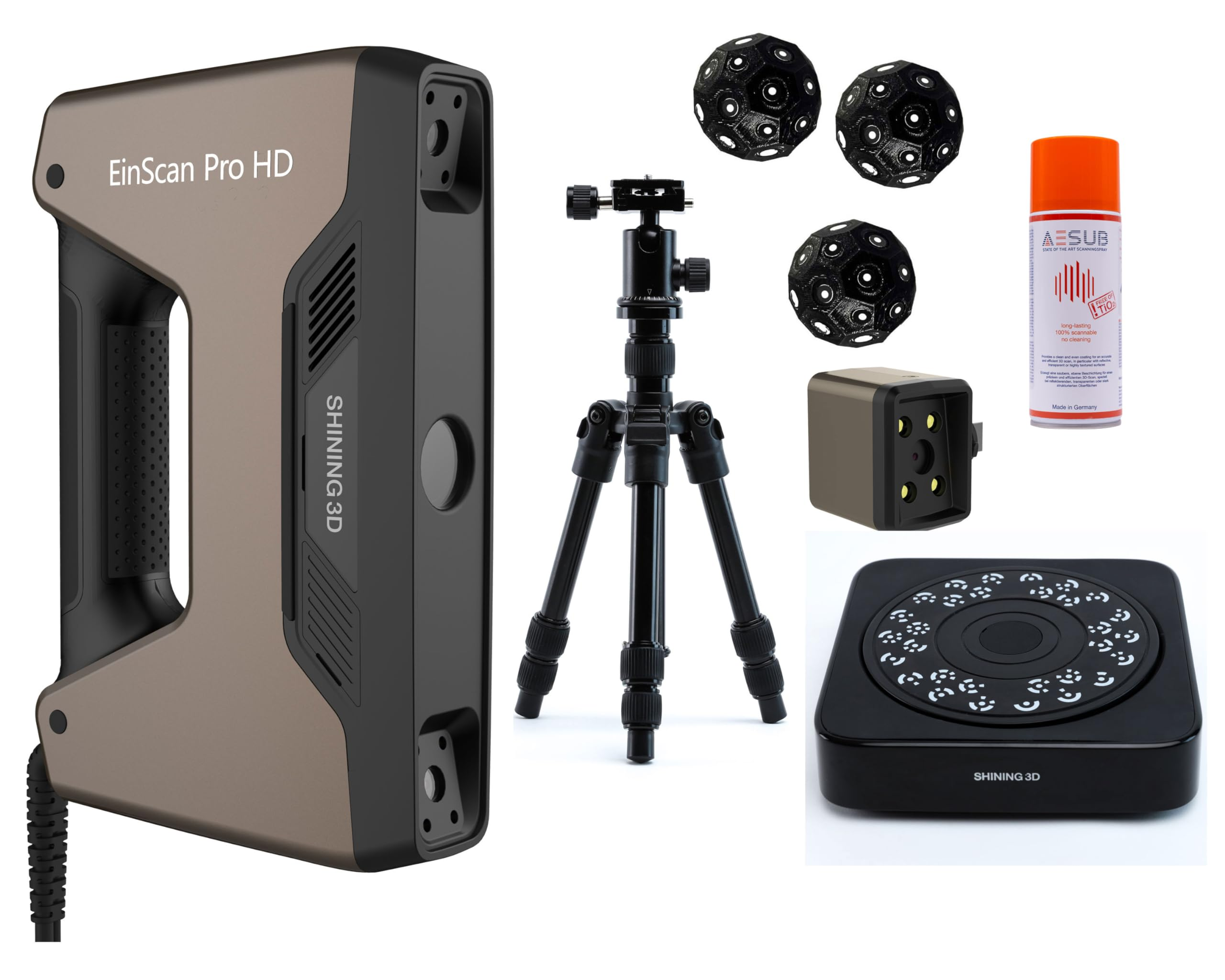 At the beginning of this week, I started working with a handheld 3D scanner called EinScan Pro HD developed by Shining 3D. Before actually scanning, the first important step was understanding how the device sees objects and converts real-world geometry into digital data.The scanner works using structured light scanning. Instead of touching the object or using lasers, the device projects a patterned light beam onto the surface. Two cameras inside the scanner observe how this projected pattern deforms across the object. From this deformation, the software calculates depth, curvature, and spatial position.
The front section of the scanner contains: a projector that emits patterned light, dual high-resolution cameras that capture geometry, internal processing that continuously records spatial change while moving. When scanning begins, the scanner does not capture the entire object instantly. It records thousands of small frames while the operator moves around the object. Each frame contains partial geometry, and later the software aligns all frames together to reconstruct the full 3D form.
Role of Markers (Stickers)
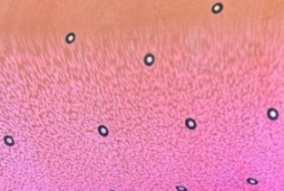 During scanning, small circular reflective stickers were placed on the object.
These markers serve an important purpose:
They act as reference points for tracking movement.
The scanner constantly identifies these markers to understand its position relative to the object.
This prevents loss of tracking when surfaces are smooth or repetitive.
Without markers, the scanner may lose orientation, especially on plain or symmetric surfaces.
During scanning, small circular reflective stickers were placed on the object.
These markers serve an important purpose:
They act as reference points for tracking movement.
The scanner constantly identifies these markers to understand its position relative to the object.
This prevents loss of tracking when surfaces are smooth or repetitive.
Without markers, the scanner may lose orientation, especially on plain or symmetric surfaces.
How the Scanner Processes Input
The workflow happening internally is: Light pattern projected onto object. Cameras capture distorted pattern. Software calculates depth using triangulation. Multiple frames recorded while moving. Frames aligned using geometry or markers. Point cloud generated. Point cloud converted into mesh surface. So essentially, the scanner converts light → image data → spatial coordinates → digital geometry. Understanding this helped me realise that scanning quality depends more on movement, lighting, and tracking stability than just pressing the scan button.
2️⃣ Live Scanning Process
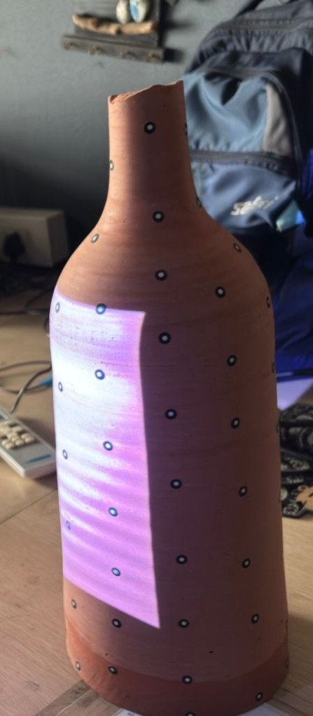 While scanning the object, a visible projected pattern appeared on the surface. This pattern is not random — it allows the scanner to read depth variation across the object.
A few practical observations during scanning: The scanner must be moved slowly and steadily. Sudden motion causes tracking loss. Maintaining a consistent distance improves accuracy. Overlapping scan areas helps alignment. I understood that scanning is similar to filming a video — continuous smooth movement produces better reconstruction than fast movements.
Before scanning, selecting the correct settings is important because they directly affect accuracy and processing quality.
Texture vs Non-Texture Scan
Texture Scan — captures colour information along with geometry.
Non-Texture Scan — focuses only on geometry and surface accuracy.
Non-texture scan was selected because shape capture was more important than colour data.
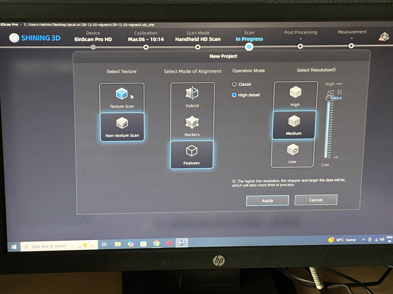
Alignment Mode
Determines how the software tracks motion:
Markers → uses stickers for tracking. Features → tracks based on geometric edges. Hybrid → combination of both. Markers mode provided stable tracking for this object. Operation Mode Classic → faster scanning. High Detail → better surface accuracy. High detail mode improves mesh precision but increases processing time. Resolution Selection
Resolution controls scan density:
High → maximum detail, heavy file size. Medium → balanced workflow. Low → faster but less detailed scan. Medium resolution was chosen to maintain both performance and quality.
Key Learning
Scanning accuracy depends heavily on operator movement. Markers improve tracking reliability. Correct software settings reduce reconstruction errors. Understanding scanning principles helps avoid post-processing issues. This session established the foundation for converting physical objects into digital models before moving into CAD editing and fabrication workflows.
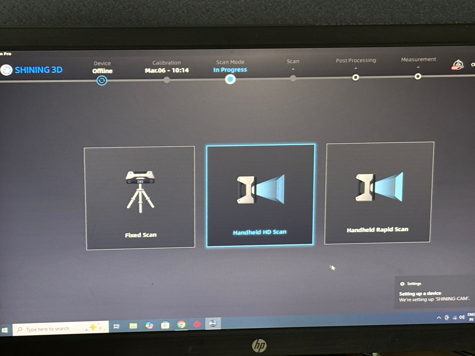
Issue Faced During Scanning — Camera Preview Not Working
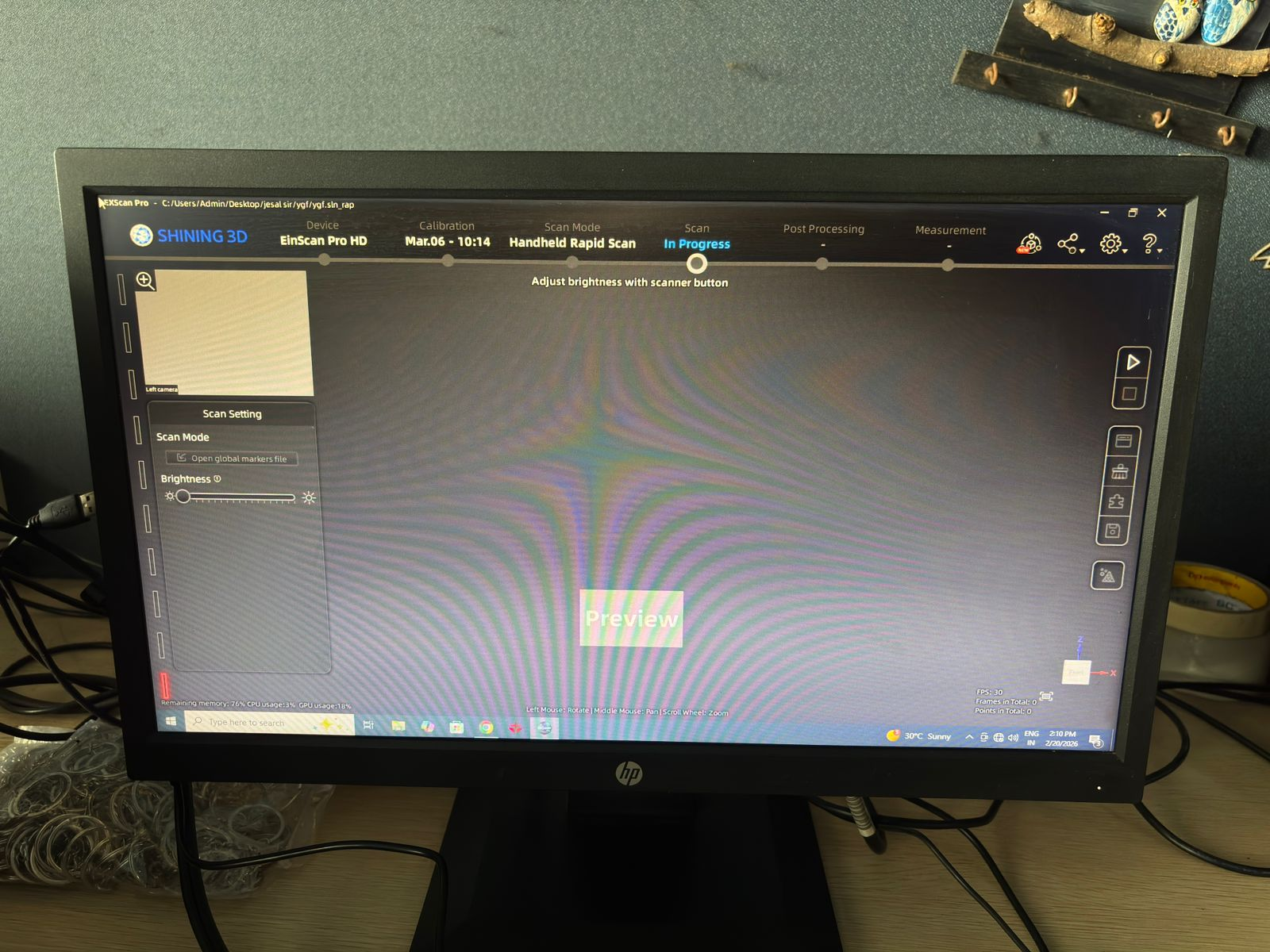 During the scanning process, an issue occurred where the camera preview suddenly stopped displaying inside the Shining3D scanning software. Even though the device was connected, the preview window appeared blank and scanning could not proceed.
This helped me understand that 3D scanning systems depend on continuous communication between hardware sensors and software drivers. If any part of this communication breaks, the scanner cannot capture geometry.
During the scanning process, an issue occurred where the camera preview suddenly stopped displaying inside the Shining3D scanning software. Even though the device was connected, the preview window appeared blank and scanning could not proceed.
This helped me understand that 3D scanning systems depend on continuous communication between hardware sensors and software drivers. If any part of this communication breaks, the scanner cannot capture geometry.
Exploring Mobile 3D Scanning Using LiDAR
After facing issues with the handheld scanner camera preview, I decided to experiment with an alternative approach — mobile 3D scanning. Modern Apple iPhone Pro devices include a built-in LiDAR sensor, which allows quick depth capture directly from the phone. I used the application Polycam to test whether a phone-based workflow could produce usable scan geometry.
How LiDAR Scanning on Phone Works
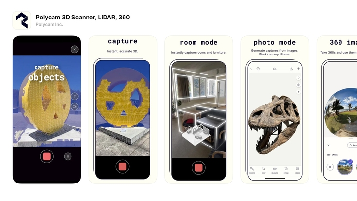
Unlike the EinScan device, which projects structured light patterns and captures highly detailed deformation through dual cameras, the iPhone uses LiDAR (Light Detection and Ranging).
The working principle is different: The phone emits invisible infrared light pulses. These light rays bounce back from surfaces. The sensor measures time taken for light to return. Distance is calculated from this timing. The software continuously combines depth frames into a 3D model. So instead of capturing fine surface distortion like structured light scanners, LiDAR mainly builds a depth map of the environment.
Observation During Scanning
The scanning process was fast and easy: No markers required. Real-time mesh appeared instantly. Entire object captured in a single continuous pass. However, the final model did not reproduce the exact form accurately. Certain areas looked smoothed, merged, or slightly inflated compared to the real object.
Why the Form Was Not Accurate (Correct Understanding)
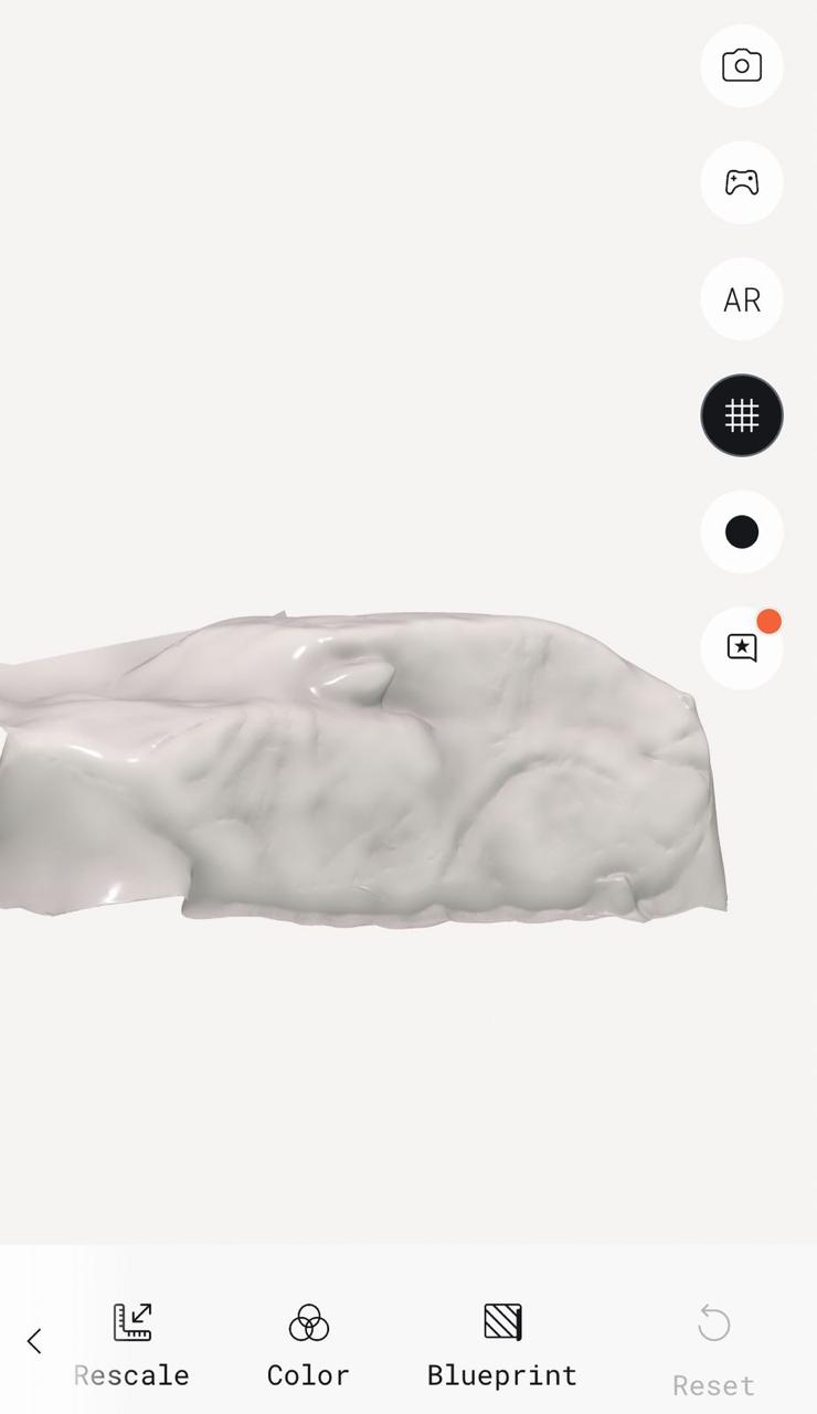 Your assumption is partly right, but the reason is more specific:
LiDAR collects fewer depth points compared to professional scanners.
It prioritizes creating a complete 3D scene rather than precise geometry.
The software fills missing data by interpolating surfaces.
Small features and sharp edges get averaged into smoother shapes.
Mesh reconstruction algorithms merge multiple frames into one continuous render.
Your assumption is partly right, but the reason is more specific:
LiDAR collects fewer depth points compared to professional scanners.
It prioritizes creating a complete 3D scene rather than precise geometry.
The software fills missing data by interpolating surfaces.
Small features and sharp edges get averaged into smoother shapes.
Mesh reconstruction algorithms merge multiple frames into one continuous render.
So the issue was not simply combining geometry, but rather:
👉 the phone generates a low-density point cloud, and the software predicts surfaces between points to create a full model. Professional scanners like EinScan capture millions of precise points, while phone LiDAR captures coarser spatial information optimized for AR and room scanning
Transition to 3D Printing and Machine Understanding
After understanding 3D scanning workflows, the next phase of the week focused on 3D printing experimentation. Instead of directly printing final models, the approach was to first understand how the printer behaves mechanically and materially.
The goal was to learn: how geometry affects strength, how slicer settings influence results, and how motion mechanisms translate into physical performance.
1️⃣ Preparing G-Code Using Creality Print 6 Before printing, models were prepared using Creality Print (Version 6).
The slicing stage converts CAD models into machine instructions called G-code, which defines: nozzle movement (X, Y, Z motion), extrusion amount, printing speed, layer formation strategy.
While preparing prints, the following parameters were explored:
Key Settings Tested
Layer height — affects surface finish and accuracy. Infill type & density — controls internal strength and material usage. Support generation — required for overhang regions. Brim adhesion — improves bed sticking and prevents warping. Printing speed — influences dimensional accuracy. Rather than using default settings, adjustments were made intentionally to observe how each parameter changed print behavior.
🟢 1️⃣ Sketch Stage (2D Profile Creation)
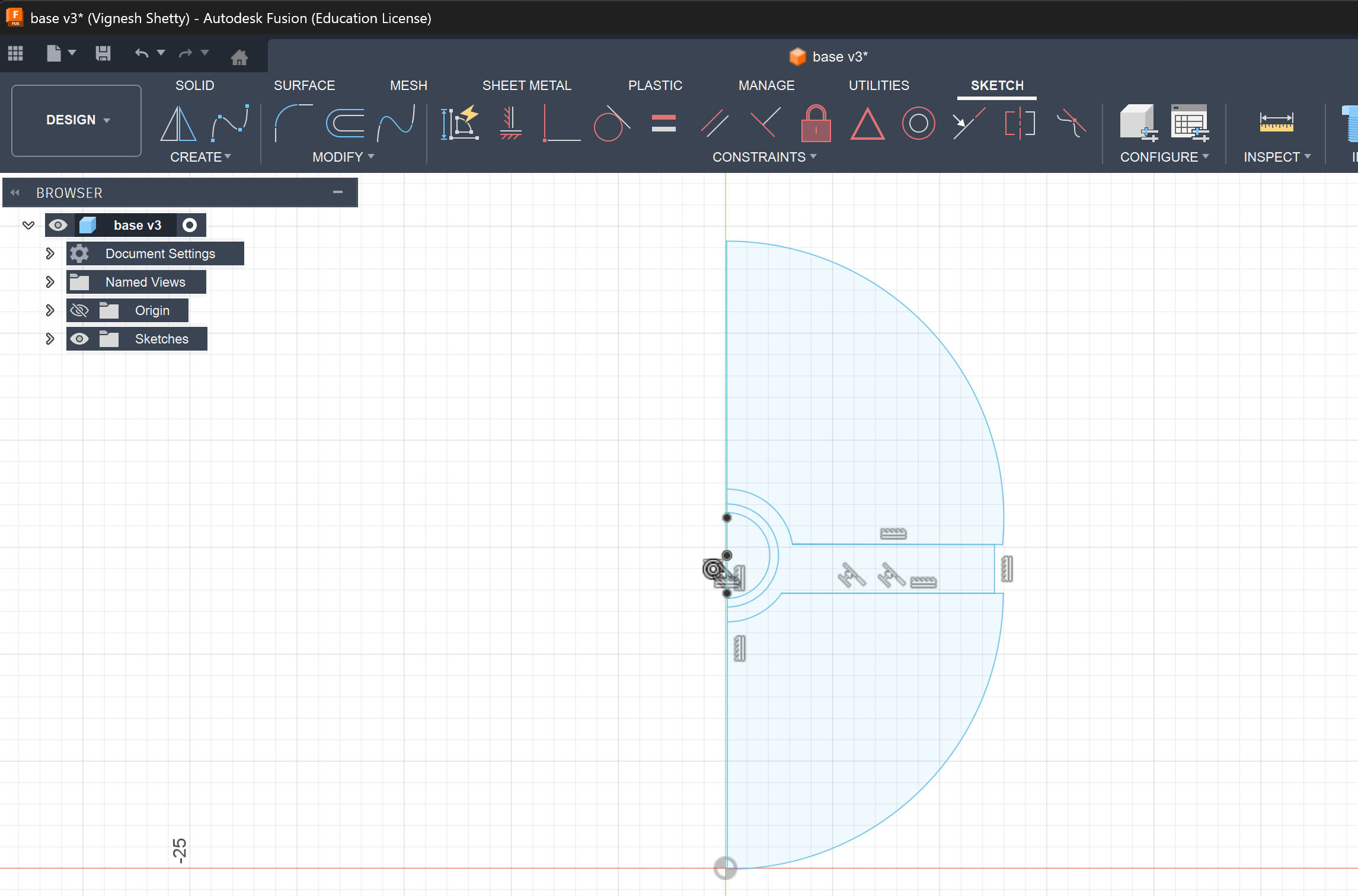 This stage shows the initial 2D sketch created in Fusion 360, which defines the base geometry of the object. A half-profile of the sphere is drawn using arcs and constrained with a central vertical axis. This axis acts as the reference for a revolve operation, ensuring symmetry in the final form. Additional inner circles indicate mounting or functional features like slots or internal cavities. The sketch is fully constrained to maintain dimensional accuracy and prevent unintended deformation. This step is critical because the entire 3D geometry depends on the precision of this profile.
⚪ 2️⃣ Solid Model (Revolve Form)
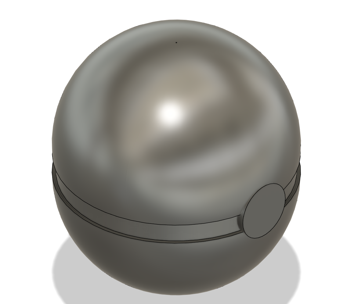 In this stage, the 2D sketch is revolved around the central axis to generate a 3D solid body. The result is a smooth spherical enclosure with a clear split line, indicating two halves of a casing. A circular side feature is added, likely representing a button, port, or mechanical interface. The geometry is still in a clean parametric solid form, meaning it is mathematically defined and editable. Fillets and smooth curvature transitions ensure manufacturability and aesthetic quality. This stage represents the ideal, watertight CAD model before moving into mesh-based workflows.
🔘 3️⃣ Feature Refinement (Detail Addition)
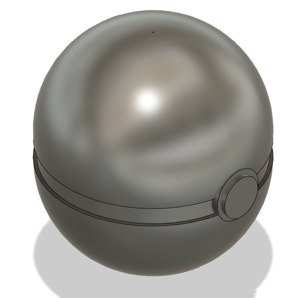
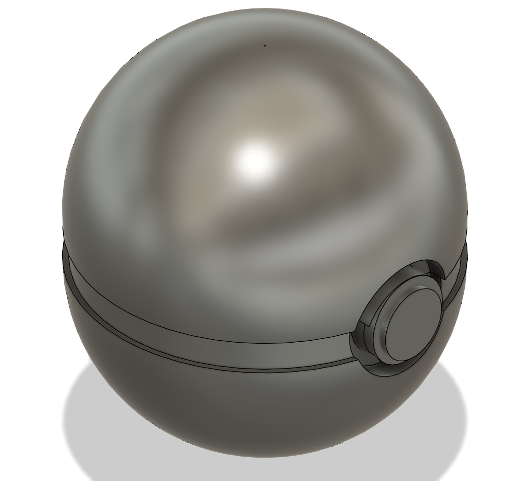 Here, additional features are introduced to enhance functionality and realism. The circular side element is refined into a more defined boss or embedded feature, possibly for interaction or assembly. The separation line between the two halves becomes more pronounced, suggesting a manufacturable split for 3D printing or molding. At this stage, design intent is clarified transitioning from pure form to functional product. These details also influence how the object will be assembled or accessed internally. This step bridges conceptual geometry and practical product design.
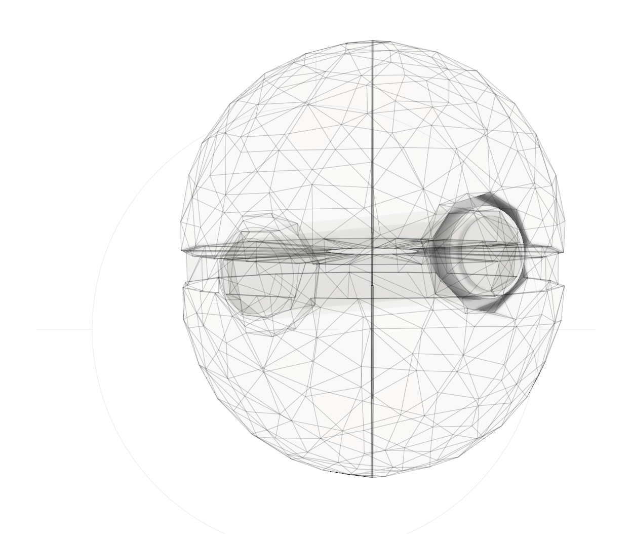
🔵 4️⃣ Form / Mesh Conversion (T-Spline / Polygon Structure)
 This image shows the model converted into a mesh representation composed of triangular polygons. Unlike solid CAD, mesh models approximate surfaces using discrete facets, which is essential for 3D scanning and printing workflows. The internal geometry and features are now represented as a network of interconnected edges and vertices. This step often happens after importing scanned data or preparing models for mesh-based operations. While flexible, mesh models are less editable compared to parametric solids. This stage is crucial for bridging CAD design with real-world scanned data.
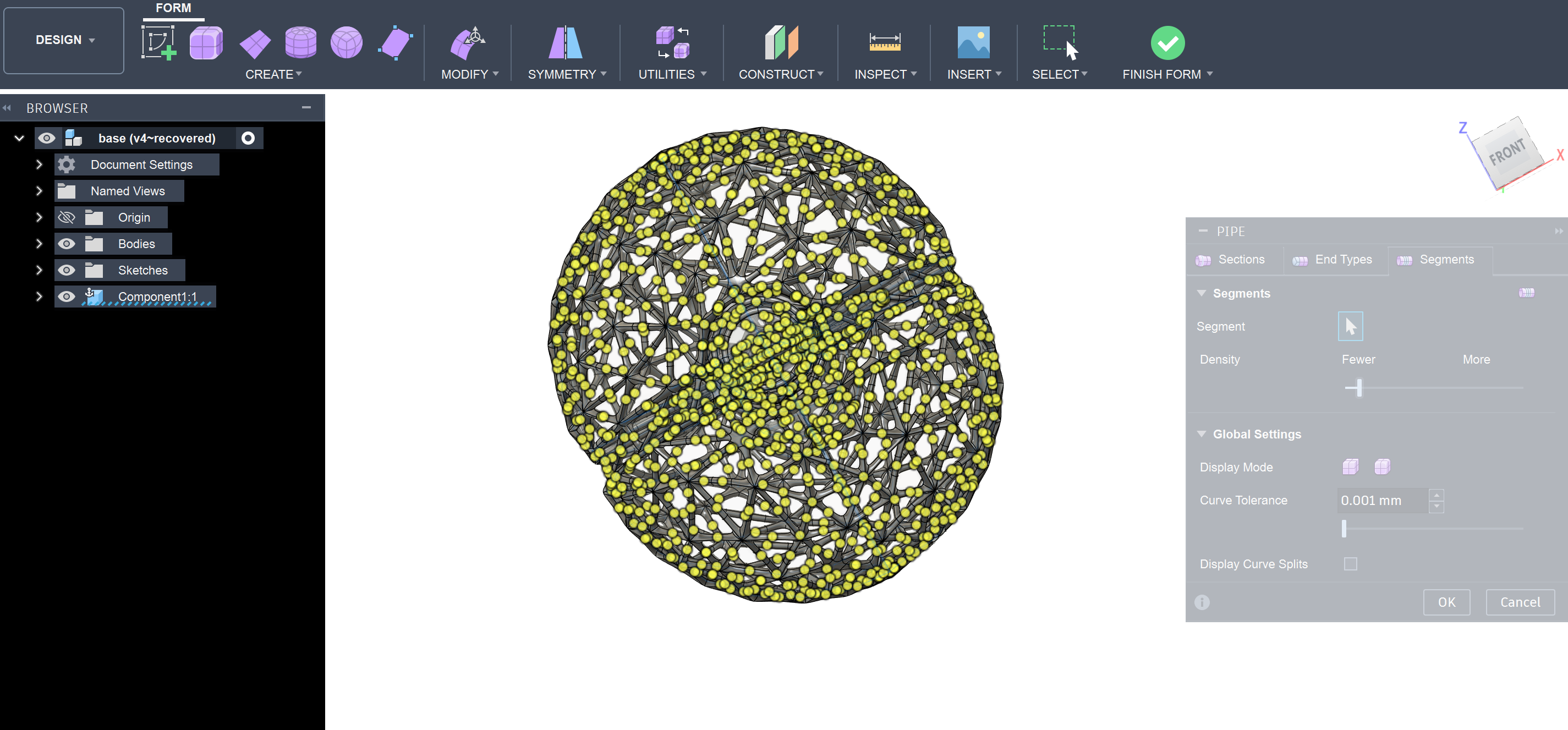
🟡 5️⃣ Point Distribution / Mesh Density Visualization
 This stage highlights the density and distribution of mesh vertices across the model surface. The yellow points represent nodes that define the mesh geometry, showing how detailed or coarse the mesh is. Higher density areas indicate regions with more complexity or curvature. Controlling mesh density is important for balancing accuracy and computational efficiency. Too many vertices increase file size and processing time, while too few reduce surface quality. This visualization helps optimize the model before converting it into structural or printable formats.
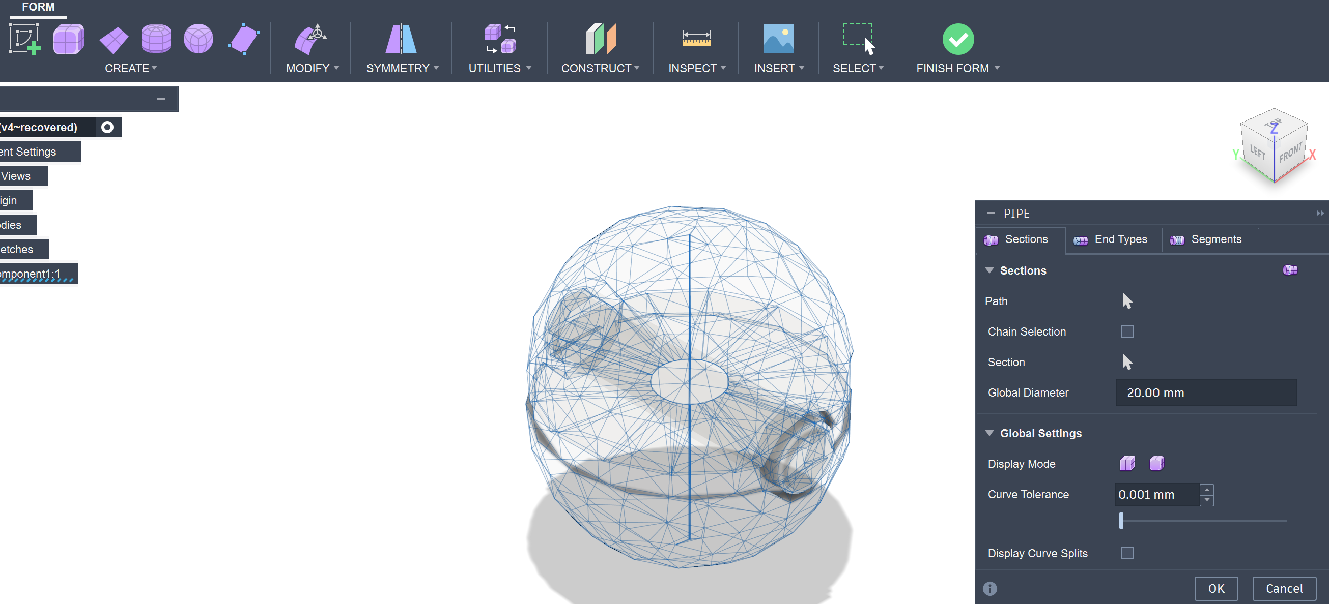
🧩 6️⃣ Pipe / Wireframe Structure Generation
 In this step, the mesh edges are converted into pipe structures, creating a lattice or wireframe model. Each edge of the mesh becomes a cylindrical member, forming a structural network across the surface. This technique is commonly used in lightweight structures, generative design, and artistic forms. The diameter of the pipes is controlled parametrically, affecting strength and visual density. This transformation turns a surface model into a volumetric framework. It’s especially useful for reducing material usage while maintaining structural integrity.
⚙️ 7️⃣ Final Lattice Model (Refined Structure)
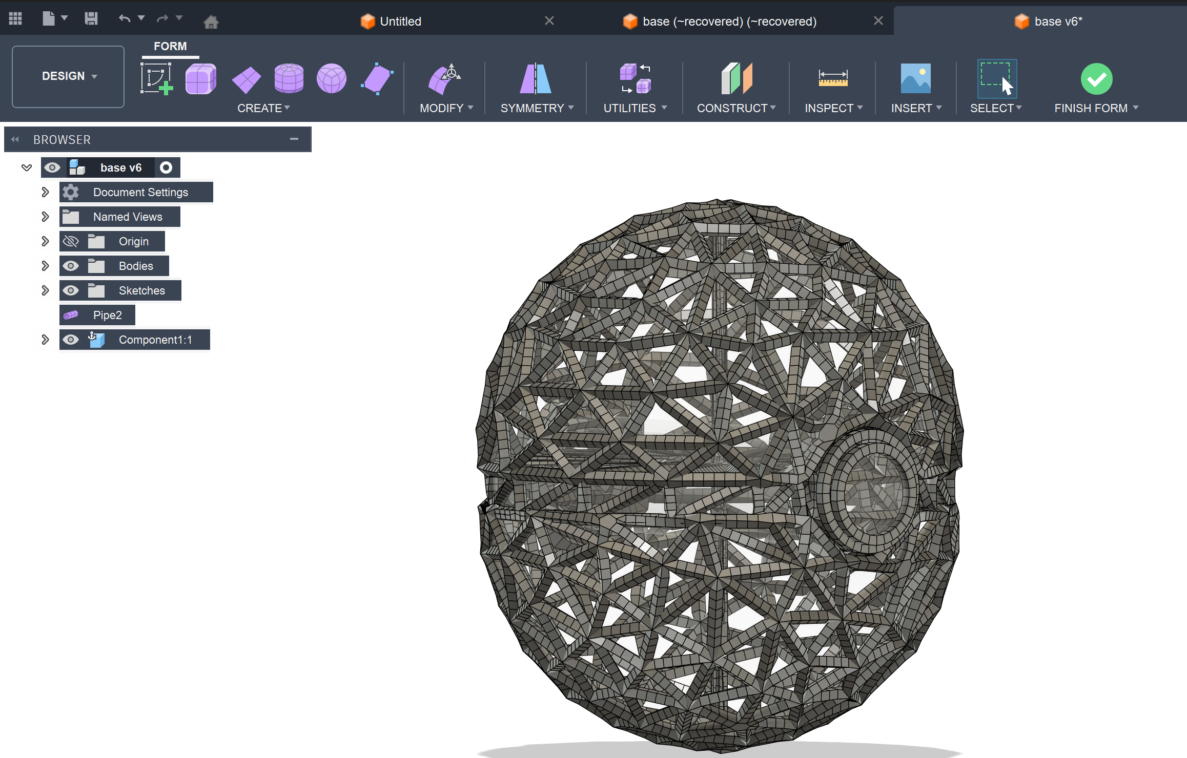
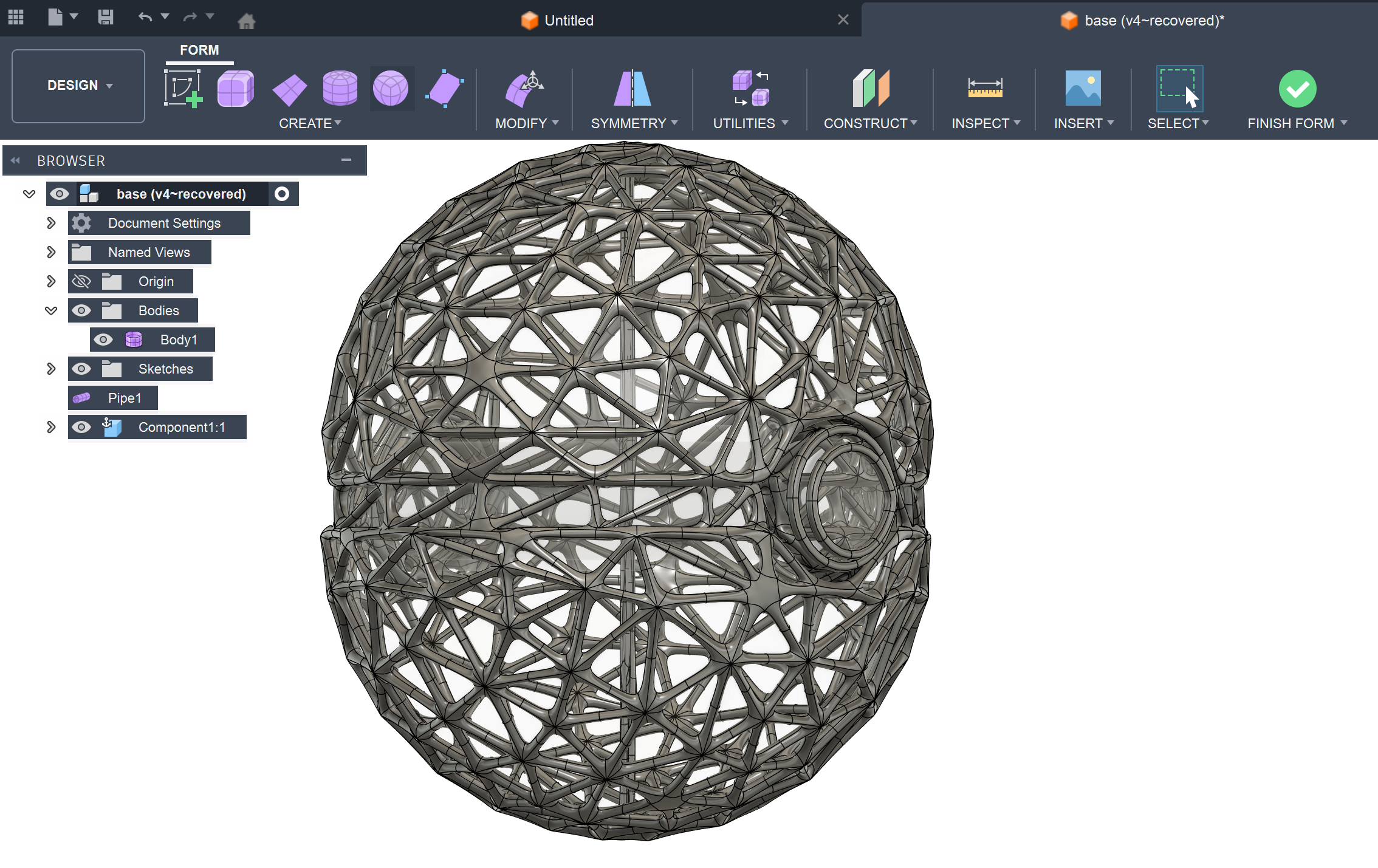 This is the finalized lattice structure after applying pipe operations and smoothing. The model now consists of interconnected cylindrical elements forming a rigid yet lightweight shell. The original spherical form is preserved, but now expressed through a complex geometric network. This structure is highly suitable for 3D printing, especially with technologies like FDM or resin printing. It demonstrates an advanced transition from solid modeling to computational design. The final output balances aesthetics, strength, and material efficiency
8️⃣ 3D Printed
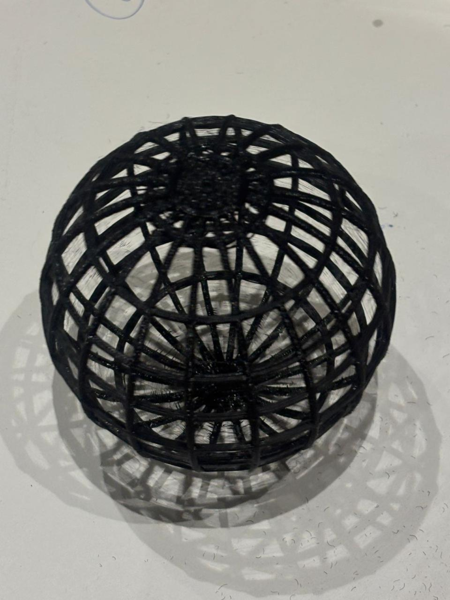
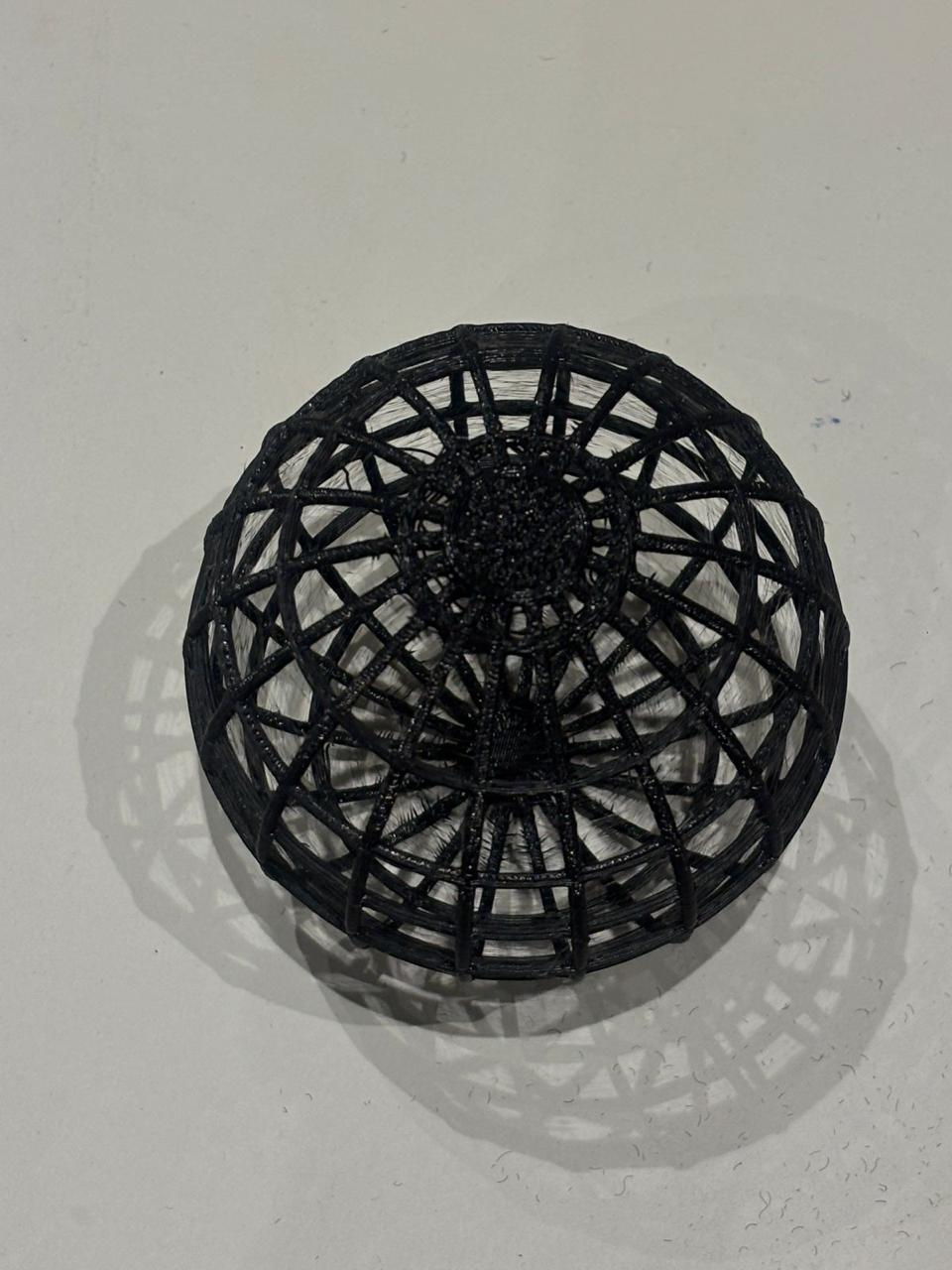 The final output of this process is a 3D printed lattice structure derived from a parametric spherical model. The design was initially created using a sketch-based revolve, followed by conversion into a mesh and further transformed into a pipe-based wireframe structure. This lattice approach significantly reduces material usage while maintaining the overall form and structural integrity of the object. The model was fabricated using a standard FDM 3D printer with filament, where the thin interconnected members required careful consideration of print settings such as layer height, speed, and support. Minor stringing and surface roughness are visible, which are typical in fine lattice prints and can be improved with optimization or post-processing. Overall, the final print successfully demonstrates the transition from solid modeling to mesh manipulation and structural abstraction, highlighting both the capabilities and limitations of additive manufacturing in complex geometries