14. Interface and application programming
Group assignment:
- Compare as many tool options as possible
To see our group assignment click here
Individual assignment:
- Write an application that interfaces a user with input and/or output device(s) on a board that you made.
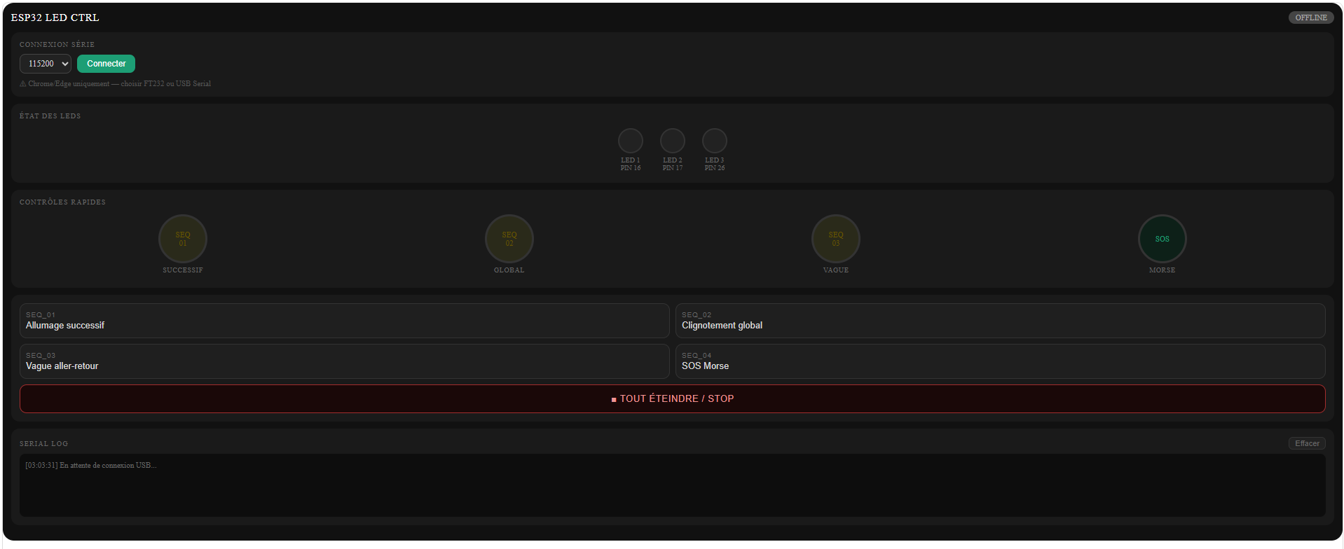
ESP32 LED Controller
Individual assignment:
Design and program a web interface to control LEDs connected to an ESP32 microcontroller via serial USB communication using an FTDI cable.
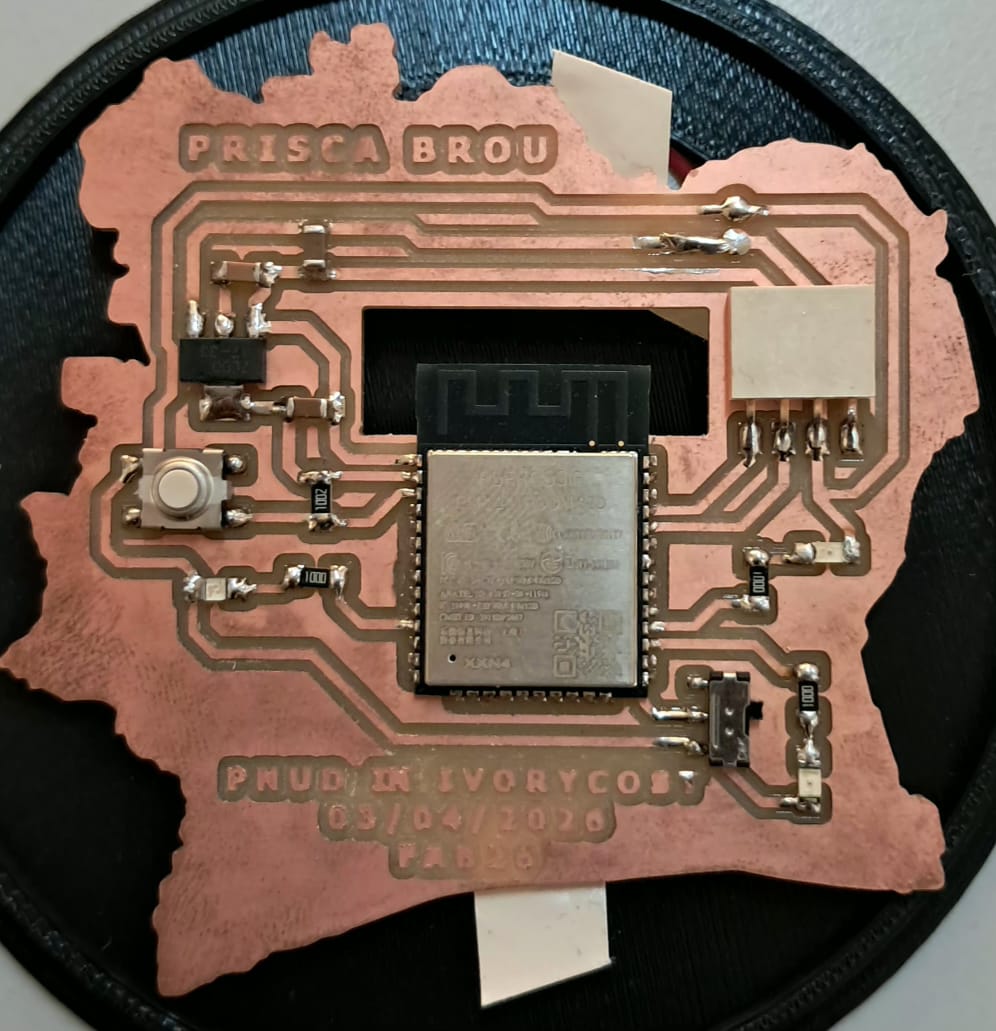
My Setup
The LEDs are connected to the ESP32 development board I used during the Y'ello Lab Fab Lab sessions.
Hardware
- Microcontroller: ESP32 (development board)
- USB-Serial adapter: FTDI cable (FT232R)
- LEDs: 3 × standard LEDs
- Resistors: 3 × 220 Ω
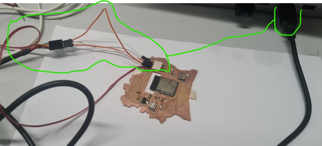
System Architecture
The system uses the browser's Web Serial API to send text commands over USB to the ESP32 via an FTDI cable. No Wi-Fi or external server is needed.
Wiring
FTDI → ESP32
| FTDI Pin | ESP32 Pin | Note |
|---|---|---|
| TX | RX (GPIO 3) | Crossed: TX - RX |
| RX | TX (GPIO 1) | Crossed: RX - TX |
| GND | GND | Mandatory — shared ground |
| VCC 3.3V | 3V3 | If powering via FTDI |
LEDs - ESP32
| ESP32 Pin | Component | To |
|---|---|---|
| GPIO 16 | 220 Ω LED 1 anode | Cathode GND |
| GPIO 17 | 220 Ω LED 2 anode | Cathode GND |
| GPIO 26 | 220 Ω LED 3 anode | Cathode GND |
Communication Protocol
Commands sent by the interface (PC → ESP32)
SEQ:1\n   →  Sequential lighting
SEQ:2\n   →  Global blink
SEQ:3\n   →  Wave back and forth
SEQ:4\n   →  SOS Morse
STOP\n    →  Turn everything off
Responses sent by the ESP32 (ESP32 - PC)
READY         -  On startup
LEDS:1,0,0    -  LED 1 ON, LED 2 OFF, LED 3 OFF
CMD: SEQ:1    -  Command echo confirmation
Code
Arduino
const int    BAUD_RATE = 115200;
const int    LEDS[]    = {16, 17, 26};
const int    NB_LEDS   = 3;

const int T_SUCCESSIVE   = 400;
const int T_CLIGNOTEMENT = 500;
const int T_VAGUE        = 280;
const int T_SOS          = 180;

int  seqActive    = 0;
int  etape        = 0;
bool bascule      = false;
unsigned long tDernier = 0;

const int VAGUE[]     = {0, 1, 2, 1};
const int VAGUE_LEN   = 4;
const int SOS_MOTIF[] = {1,0,1,0,1,0,0, 3,0,3,0,3,0,0, 1,0,1,0,1,0,0,0};
const int SOS_LEN     = sizeof(SOS_MOTIF) / sizeof(SOS_MOTIF[0]);

String inputLine = "";

void ledSet(int i, bool on) { digitalWrite(LEDS[i], on ? HIGH : LOW); }
void toutEteindre() { for (int i=0;i<NB_LEDS;i++) ledSet(i,false); }
void toutAllumer()  { for (int i=0;i<NB_LEDS;i++) ledSet(i,true);  }

void envoyerEtat() {
  String msg = "LEDS:";
  for (int i = 0; i < NB_LEDS; i++) {
    msg += (digitalRead(LEDS[i]) == HIGH) ? "1" : "0";
    if (i < NB_LEDS - 1) msg += ",";
  }
  Serial.println(msg);
}

void traiterCommande(String cmd) {
  cmd.trim();
  Serial.print("CMD: "); Serial.println(cmd);
  if (cmd == "STOP") {
    seqActive = 0; etape = 0;
    toutEteindre(); envoyerEtat();
  } else if (cmd.startsWith("SEQ:")) {
    int seq = cmd.substring(4).toInt();
    if (seq >= 1 && seq <= 4) {
      seqActive = seq; etape = 0; bascule = false;
      tDernier = millis(); toutEteindre(); envoyerEtat();
    }
  }
}

void lireSerial() {
  while (Serial.available()) {
    char c = (char)Serial.read();
    if (c == '\n') {
      if (inputLine.length() > 0) { traiterCommande(inputLine); inputLine = ""; }
    } else if (c != '\r') { inputLine += c; }
  }
}

void executerSequence() {
  unsigned long now = millis();
  switch (seqActive) {
    case 1:
      if (now - tDernier >= T_SUCCESSIVE) {
        toutEteindre(); ledSet(etape % NB_LEDS, true);
        etape++; tDernier = now; envoyerEtat();
      } break;
    case 2:
      if (now - tDernier >= T_CLIGNOTEMENT) {
        bascule = !bascule;
        bascule ? toutAllumer() : toutEteindre();
        tDernier = now; envoyerEtat();
      } break;
    case 3:
      if (now - tDernier >= T_VAGUE) {
        toutEteindre(); ledSet(VAGUE[etape % VAGUE_LEN], true);
        etape++; tDernier = now; envoyerEtat();
      } break;
    case 4: {
      int unite = SOS_MOTIF[etape % SOS_LEN];
      unsigned long duree = (unsigned long)(unite > 0 ? unite : 1) * T_SOS;
      if (now - tDernier >= duree) {
        (unite > 0) ? toutAllumer() : toutEteindre();
        etape++; tDernier = now; envoyerEtat();
      } break;
    }
  }
}

void setup() {
  Serial.begin(BAUD_RATE);
  for (int i = 0; i < NB_LEDS; i++) {
    pinMode(LEDS[i], OUTPUT);
    digitalWrite(LEDS[i], LOW);
  }
  delay(300);
  Serial.println("READY");
}

void loop() {
  lireSerial();
  if (seqActive > 0) executerSequence();
}
Web interface key JavaScript
The critical fix is calling requestPort({}) with no filter, so the FTDI cable appears in the browser's port list.
// Correct  no filter, all ports listed including FTDI
port = await navigator.serial.requestPort({});

// Wrong  restrictive filter that blocked the FTDI cable
port = await navigator.serial.requestPort({ filters: [{ usbVendorId: 0x10C4 }] });
Non-blocking serial read using a line buffer:
const decoder = new TextDecoderStream();
port.readable.pipeTo(decoder.writable);
const reader = decoder.readable.getReader();
let buffer = '';

while (true) {
  const { value, done } = await reader.read();
  if (done) break;
  buffer += value;
  let nl;
  while ((nl = buffer.indexOf('\n')) !== -1) {
    const line = buffer.slice(0, nl).trim();
    buffer = buffer.slice(nl + 1);
    if (line.startsWith('LEDS:')) updateLeds(line.substring(5).split(',').map(Number));
  }
}
Problems & Solutions
Problem 1 : FTDI port not visible in browser
Symptom
After clicking "Connect", the FT232/USB Serial port does not appear in the browser's port list.
Solution
The original interface used requestPort() with a restrictive usbVendorId filter that excluded the FTDI cable. Removing all filters fixed the issue.
Problem 2 : LEDs not lighting up (TX/RX inverted)
Symptom
Serial connection works, commands are sent (→ SEQ:1 visible in log), but no ← LEDS: response comes back and LEDs stay off.
Solution
TX and RX wires were swapped between the FTDI and the ESP32. Crossing them correctly fixed the communication.
Diagnostic: if → SEQ:1 appears in the log but no - LEDS: comes back, the ESP32 is not receiving data — check TX/RX wiring first.
Problem 3 : Compilation error: undefined reference to loop()
Solution
The loop() function was missing from the sketch. In Arduino, loop() is mandatory even if empty.
Problem 4 : LEDs not lighting up (hardware)
Symptom
TX/RX correctly wired and commands received, but LEDs still don't light up.
Solution
Verified with a minimal diagnostic sketch that bypasses serial communication entirely:
void setup() {
  pinMode(16, OUTPUT); pinMode(17, OUTPUT); pinMode(26, OUTPUT);
  digitalWrite(16, HIGH); delay(1000); digitalWrite(16, LOW);
  digitalWrite(17, HIGH); delay(1000); digitalWrite(17, LOW);
  digitalWrite(26, HIGH); delay(1000); digitalWrite(26, LOW);
}
void loop() {}
LEDs lit up correctly → confirmed hardware was fine, problem was in TX/RX wiring.
Threshold
- If LEDs light up with this test → software/communication issue
- If LEDs stay off → check GND connection, LED polarity, and resistor values
Results
Working
- Serial connection via FTDI cable from Chrome/Edge
- All 4 LED sequences triggered from the interface
- Real-time LED state feedback (
LEDS:1,0,0) - Visual indicators updated live in the interface
- Timestamped serial log with color-coded TX/RX
| Layer | Problem | Fix |
|---|---|---|
| Web interface | Restrictive USB filter | requestPort({}) with no filter |
| Communication | TX/RX swapped | Wires crossed correctly |
| Arduino | Missing loop() |
Added empty loop() function |
| Hardware | No shared GND | FTDI GND connected to ESP32 GND |
Soft Skills
Methodical debugging Each layer was tested independently (interface → communication → hardware) to isolate the root cause without confusion.
Log reading Observing that → SEQ:1 appeared without a ← LEDS: response immediately pointed to a reception problem on the ESP32 side, not an emission problem on the PC side.
Iteration Each error was treated as useful diagnostic information rather than a failure, allowing steady forward progress across multiple test-fix-retest cycles.
Precise technical communication Describing problems with clear symptoms, context, and screenshots enabled faster diagnosis at each step.
FILES
| Download the dashboard | Open with any browser you want