8. Electronics production
Group assignment:
-
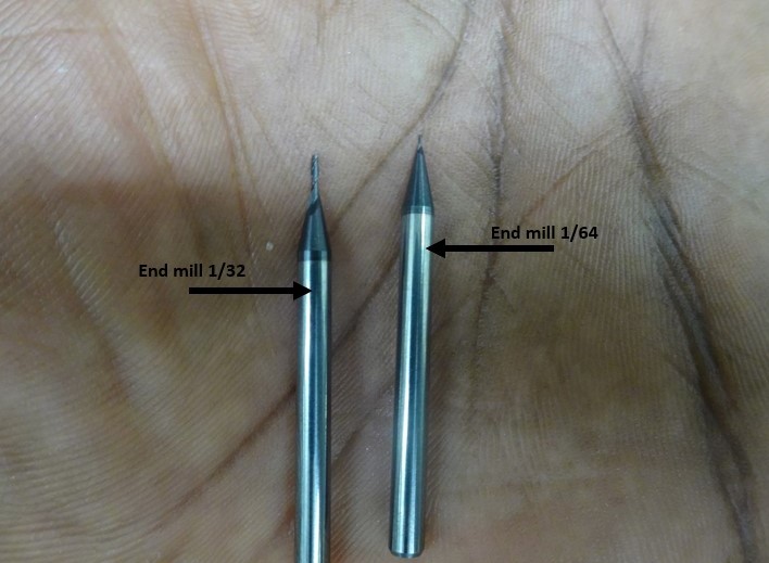
Characterize the design rules for your in-house PCB production process: document feeds, speeds, plunge rate, depth of cut (traces and outline) and tooling.
-
extra credit: send a PCB out to a board house
-
Document your work to the group work page and reflect on your individual page what you learned
To see our group assignment click here
Individual assignment:
-
Make and test the development board that you designed to interact and communicate with an embedded microcontroller
-
extra credit: make it with another process
CAM File Preparation & Manufacturing
[Electronics design week ](https://fabacademy.org/2026/labs/inphb/students/prisca-brou/assignments/week06/#individual-assignment)
CAM File Preparation
-
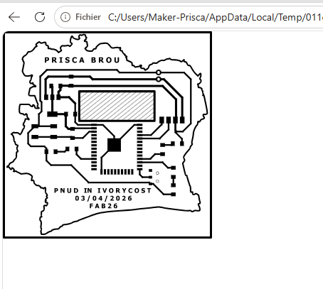
Export design files as high-resolution images (
.svg) distinguishing traces from the board outline. -
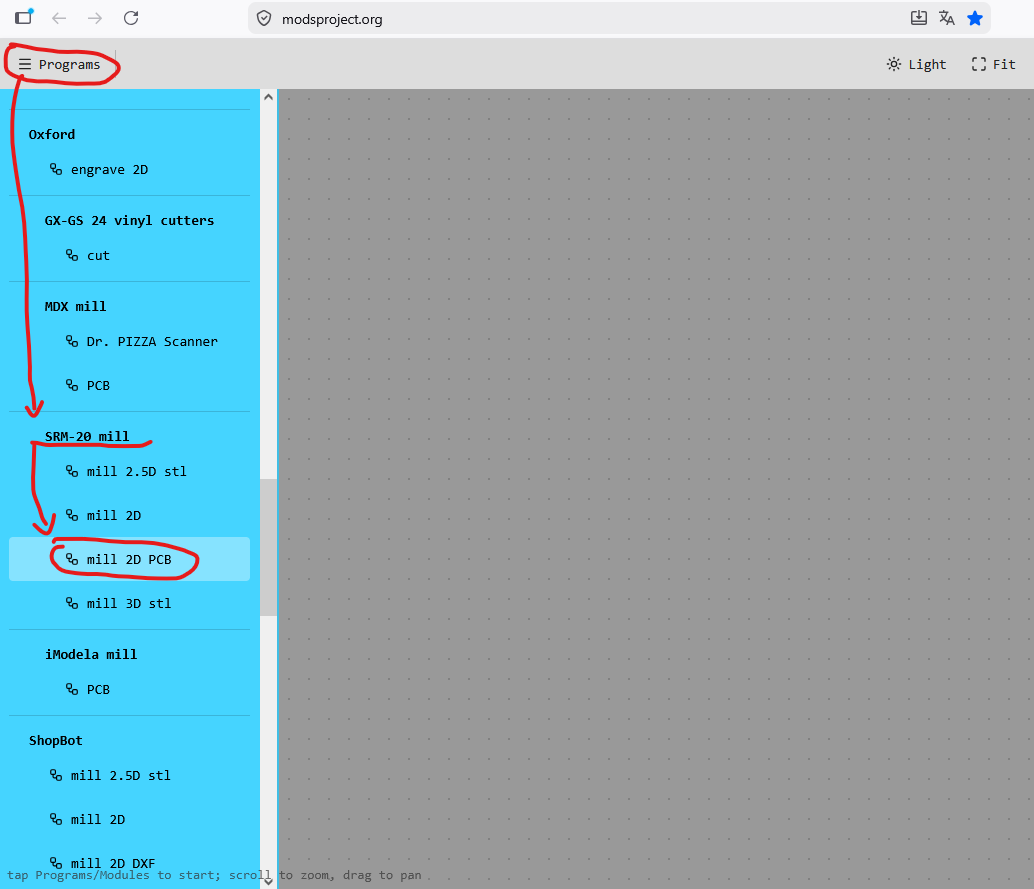
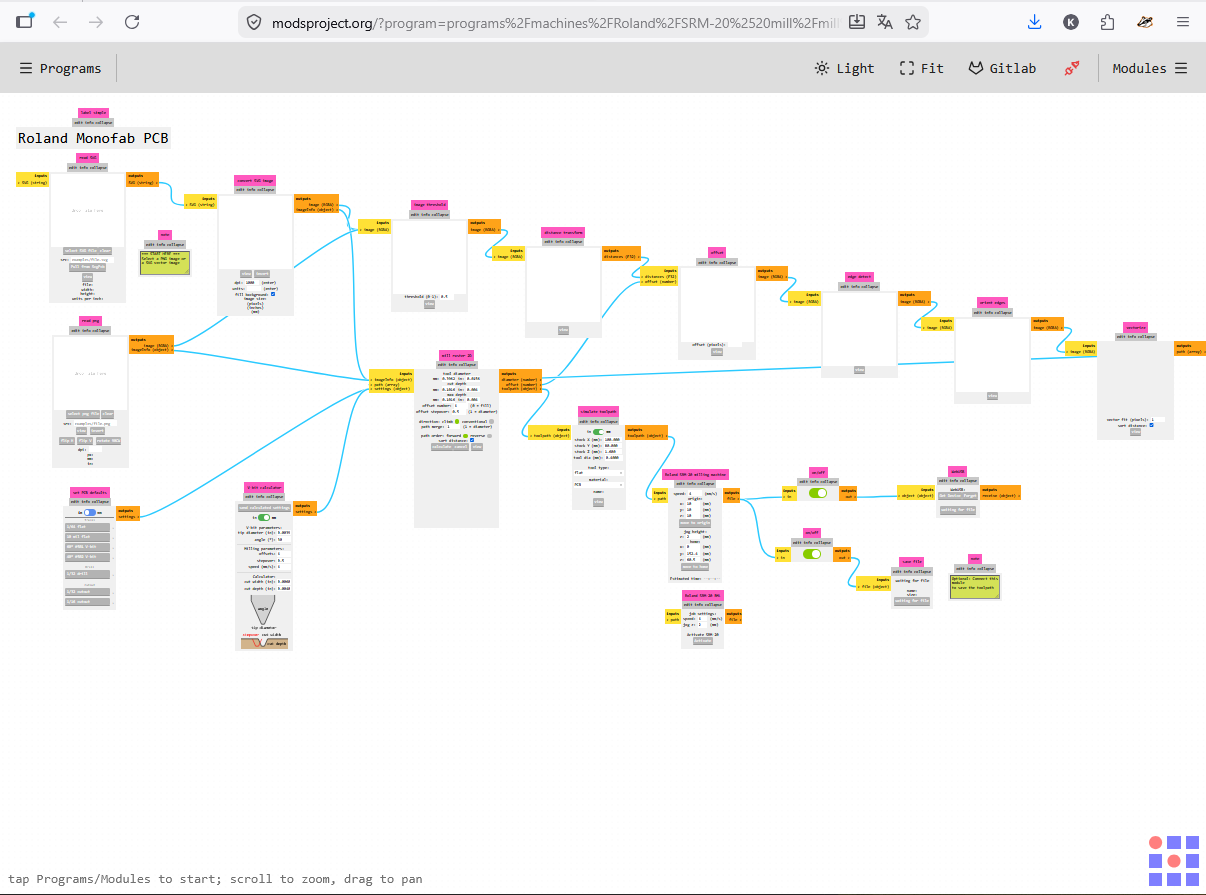
I Used mods CE software to generate toolpaths and G-code numerical control files.
VIDEO during the milling
Machining / Milling
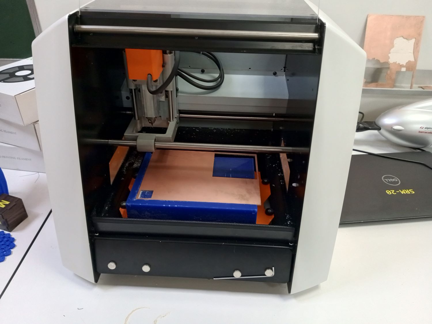
Equipment
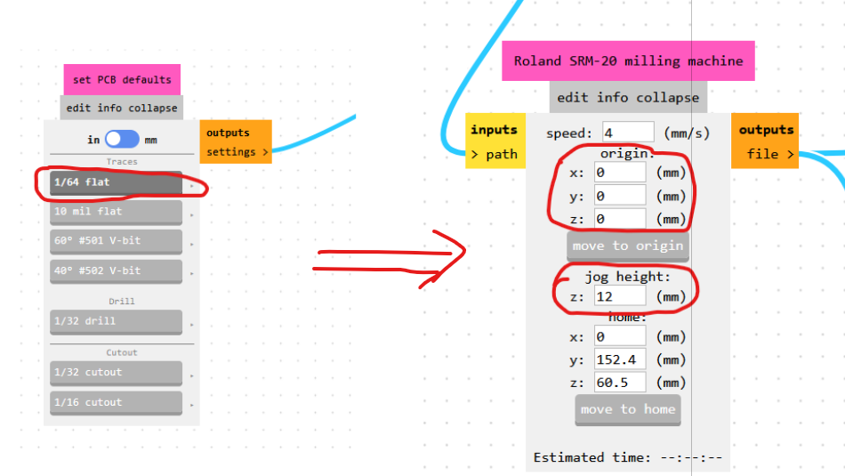
This workflow uses a Roland SRM-20 desktop milling machine.
- Fix the copper plate (FR1) onto the milling machine bed.
- Set the origin point (X, Y and Z at the copper surface).
- Mill the internal traces, then cut out and drill the board.
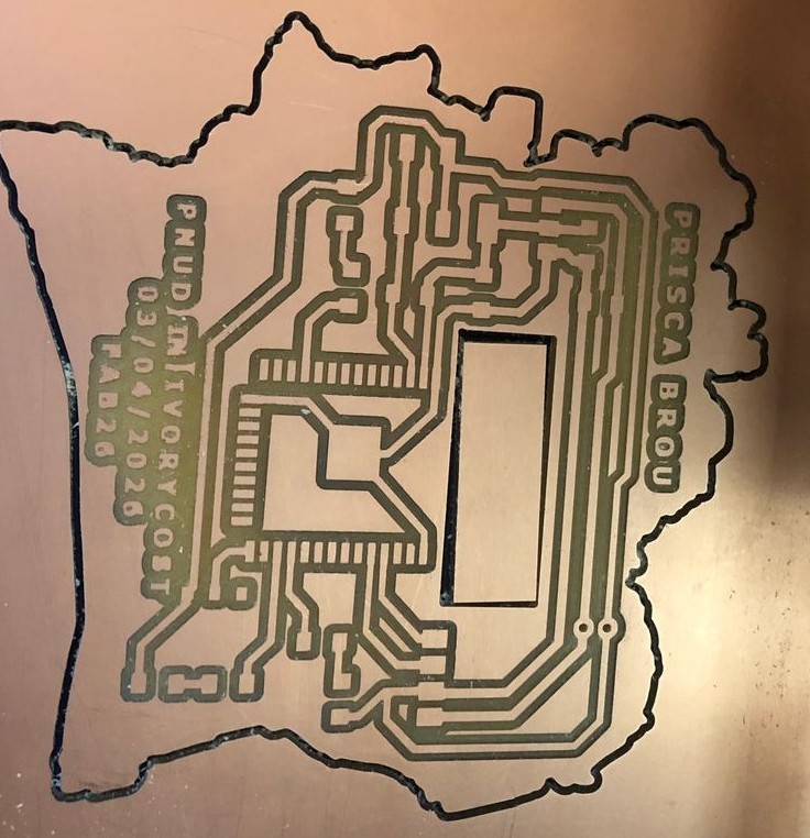
PCB AFTER PRODUCTION
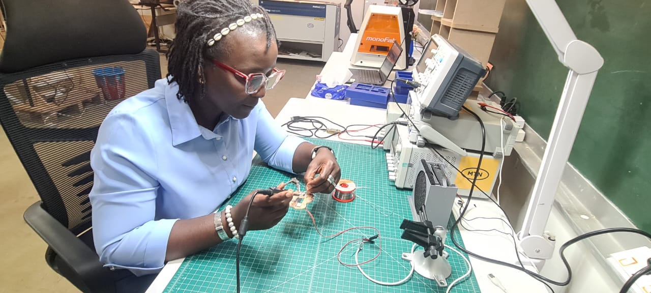
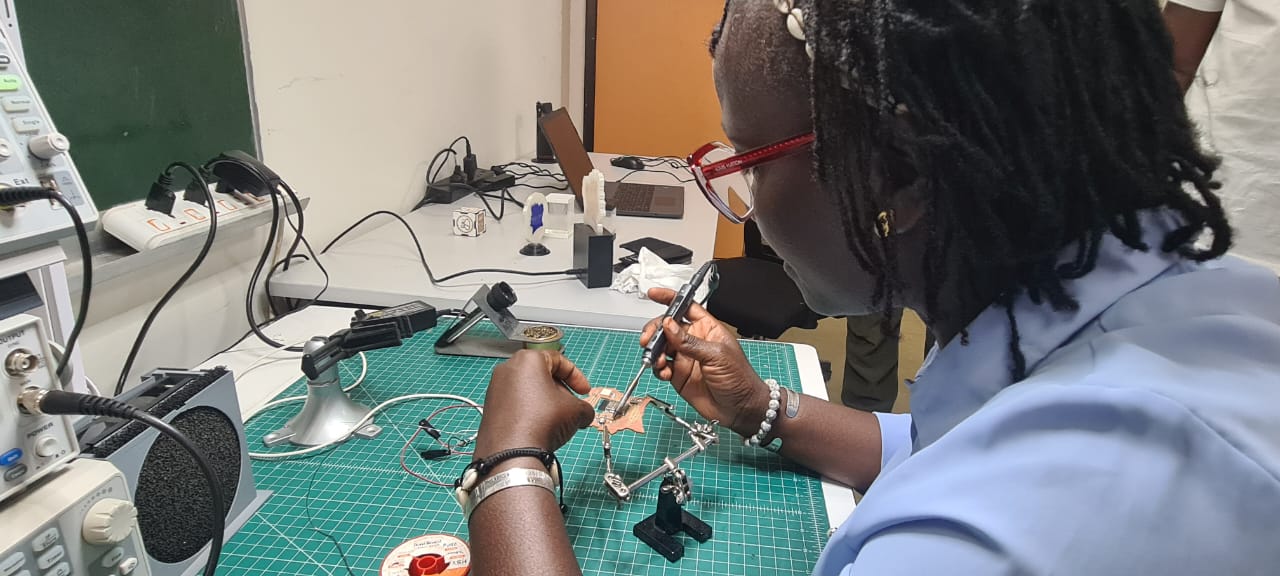
Assembly & Soldering (SMD Soldering)
Precaution
Always clean the board thoroughly after milling before soldering to remove copper dust and debris.
- Clean the board after machining.
- Solder the surface-mount components microcontroller, resistors, capacitors, connectors following the component placement plan (BOM/layout).
Soldering pictures
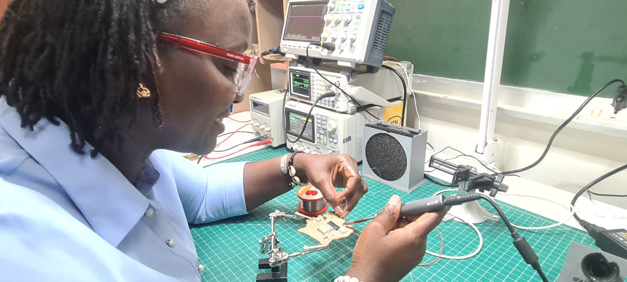
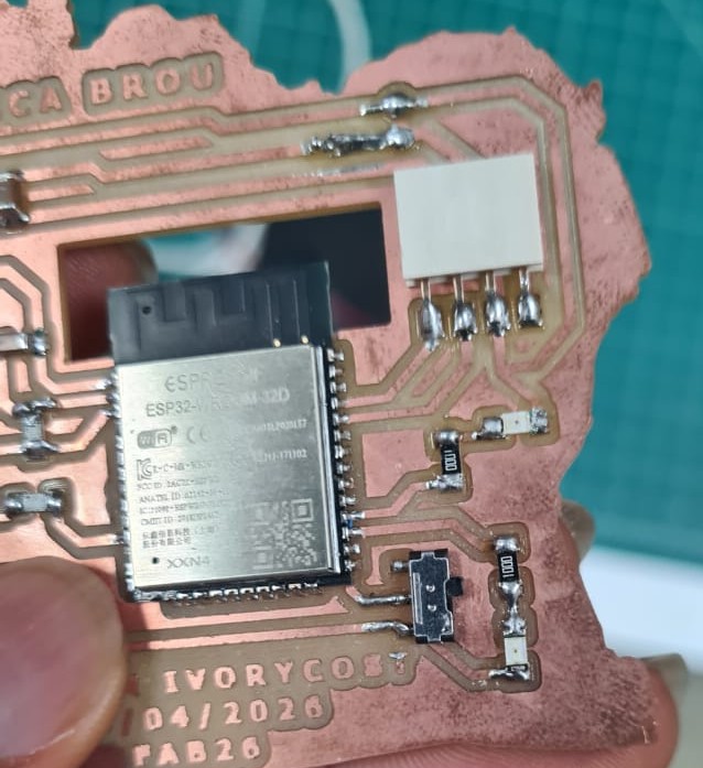
Result after soldering
Summary
| Step | Tool / Method | Output |
|---|---|---|
| Export design | KiCad | .png / SVG files |
| Generate toolpaths | mods CE | G-code files |
| Milling | Roland SRM-20 | Milled PCB |
| Soldering | Soldering iron (SMD) | Assembled PCB |
| Type | Link |
|---|---|
| Miling File | Download zip |