3. Computer controlled cutting
Group assignment:
- Characterize your laser cutter's focus, power, speed, rate, kerf, and joint clearance.
To see our group assignment click here
Individual assignments:
- Design, lasercut, and document a parametric press-fit construction kit.
- Cut something on the vinyl cutter.
Creating an Assembly Part with the Epilog Laser: Fusion Edge
Overview
This guide explains how to design and manufacture an assembly part using Inkscape, AutoCAD, and an Epilog Laser.
I will explain my press fit kit design and fabrication i also design other projetcts,
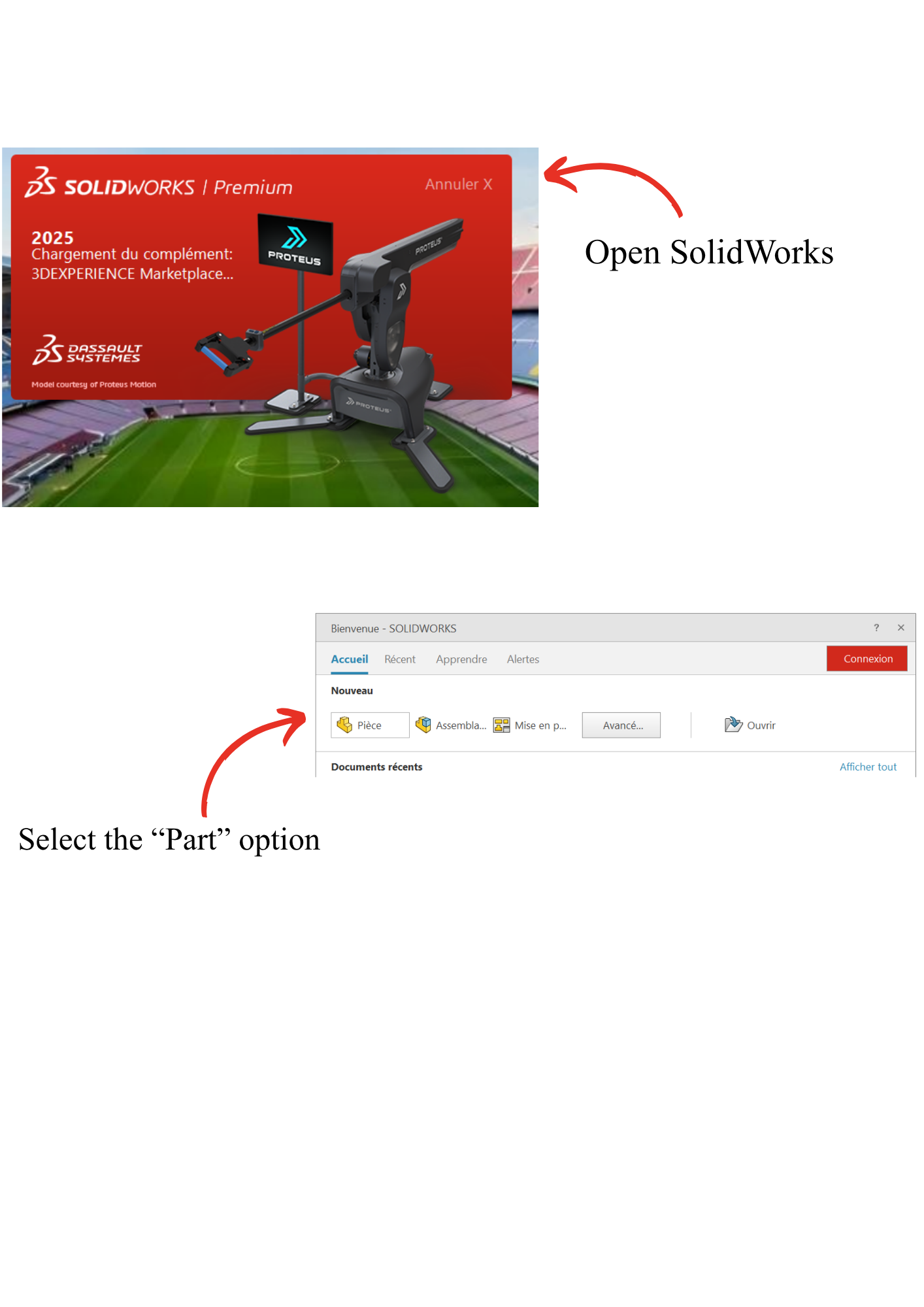
Step 1: Create a New Part
- Open SolidWorks.
- Select the Part option.
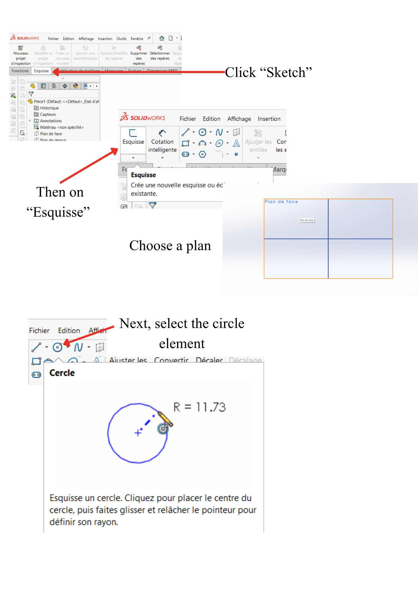
Step 2: Create a Sketch
- Click Sketch.
- Then click Sketch.
- Select a plane.
- Choose the Circle tool.
Step 3: Draw the Geometry
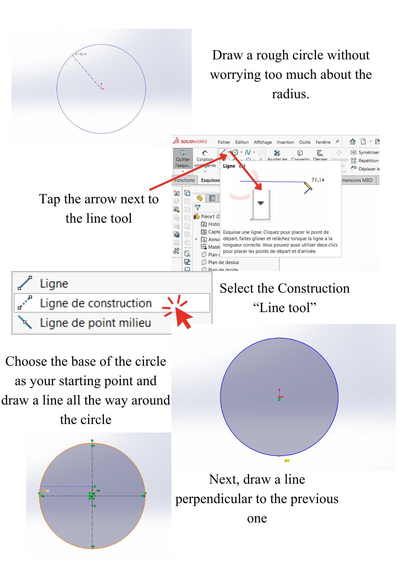
- Draw a rough circle without worrying about its radius.
- Click the arrow next to the Line tool.
- Select Construction Line.
- Start from the bottom of the circle and draw a construction line through the center.
- Draw another construction line perpendicular to the first one.
Step 4: Create the Global Variables
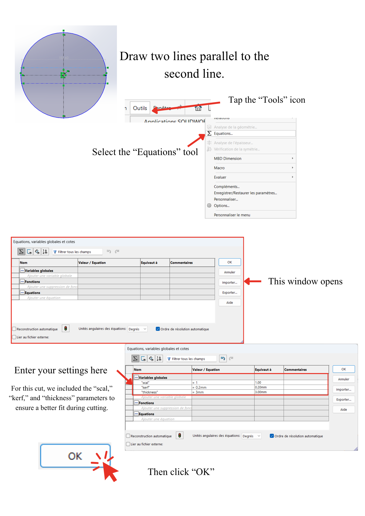
- Click Tools.
- Select Equations.
- The Equations window opens.
- Draw two lines parallel to the second construction line.
- Enter the required parameters.
- Click OK.
The parameters used are:
scalkerfthickness
Step 5: Apply the Dimensions
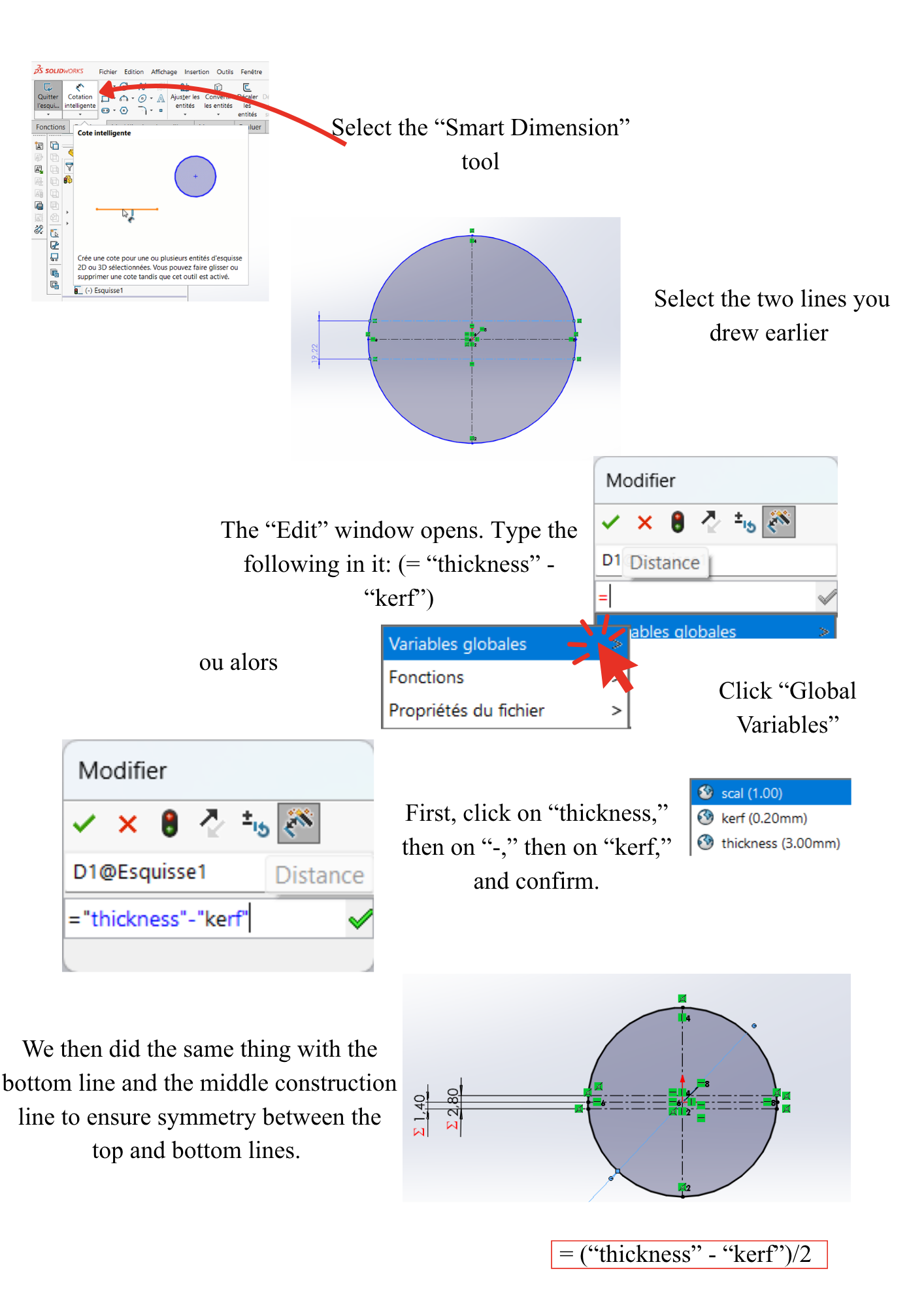
- Select the Smart Dimension tool.
- Click the two lines created previously.
- In the Edit Dimension window, type:
or
- Click Global Variables.
- Select thickness.
- Click -.
- Select kerf.
- Confirm.
Repeat the same operation between the bottom line and the center construction line to ensure symmetry.
Step 6: Dimension the Circle
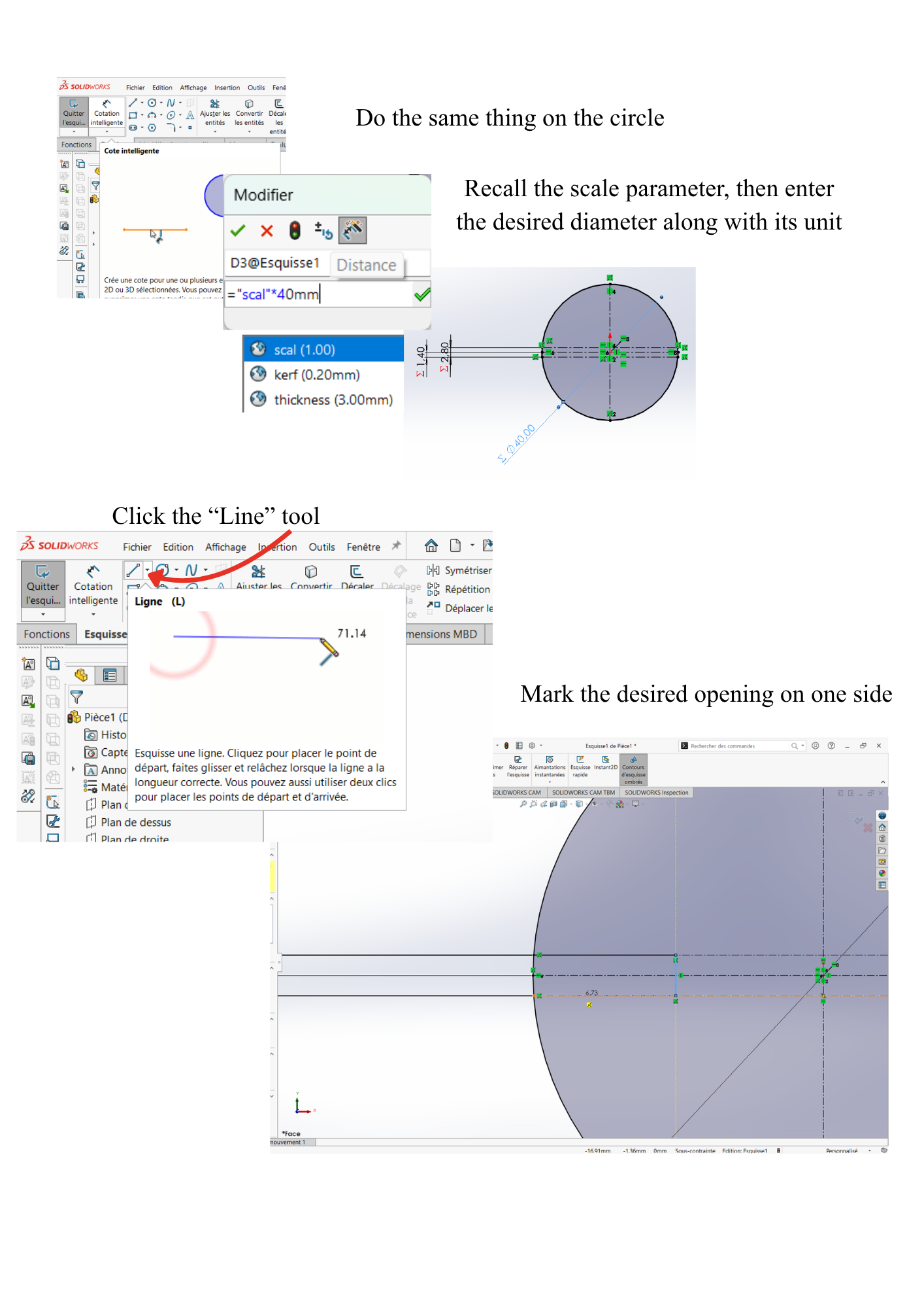
- Repeat the same procedure for the circle.
- Use the scal parameter.
- Enter the desired diameter and its unit.
- Mark the desired opening on one side.
- Select the Line tool.
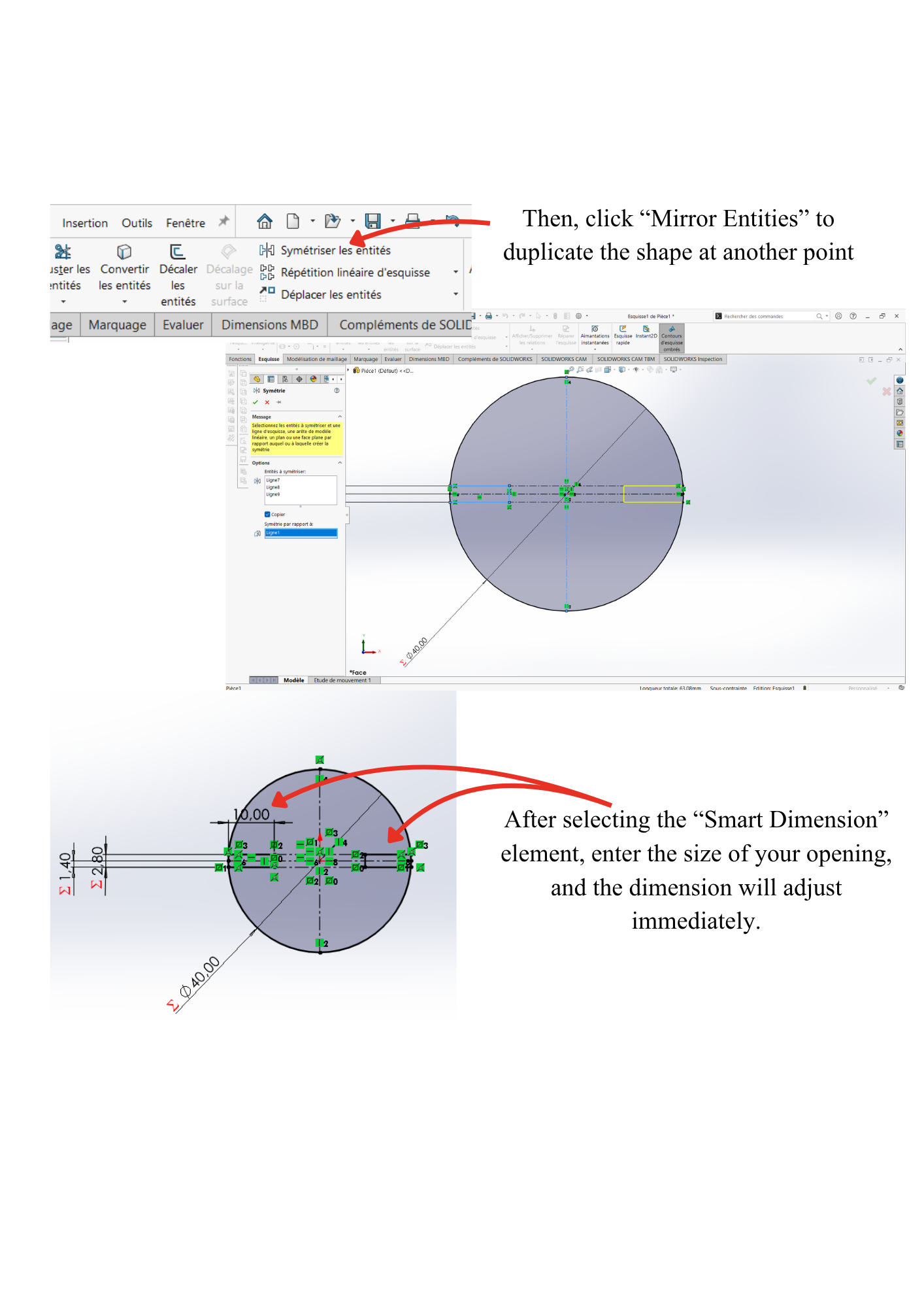
Step 7: Mirror the Geometry
- Click Mirror Entities.
- Duplicate the shape.
- Select Smart Dimension.
- Enter the width of the opening.
Step 8: Trim the Sketch
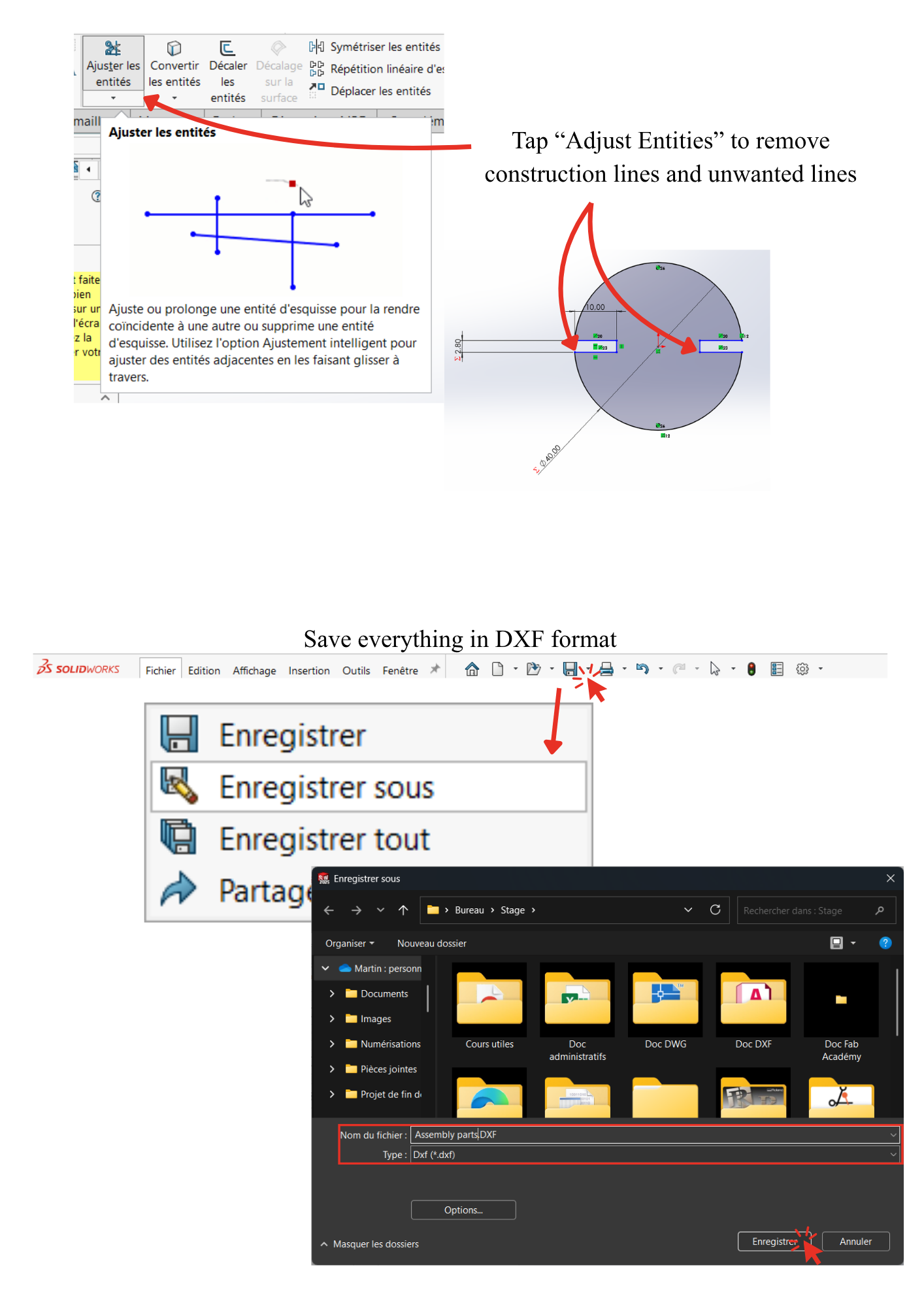
- Click Trim Entities.
- Remove all unnecessary construction lines.
- Save the file in DXF format.
Cutting Preparation
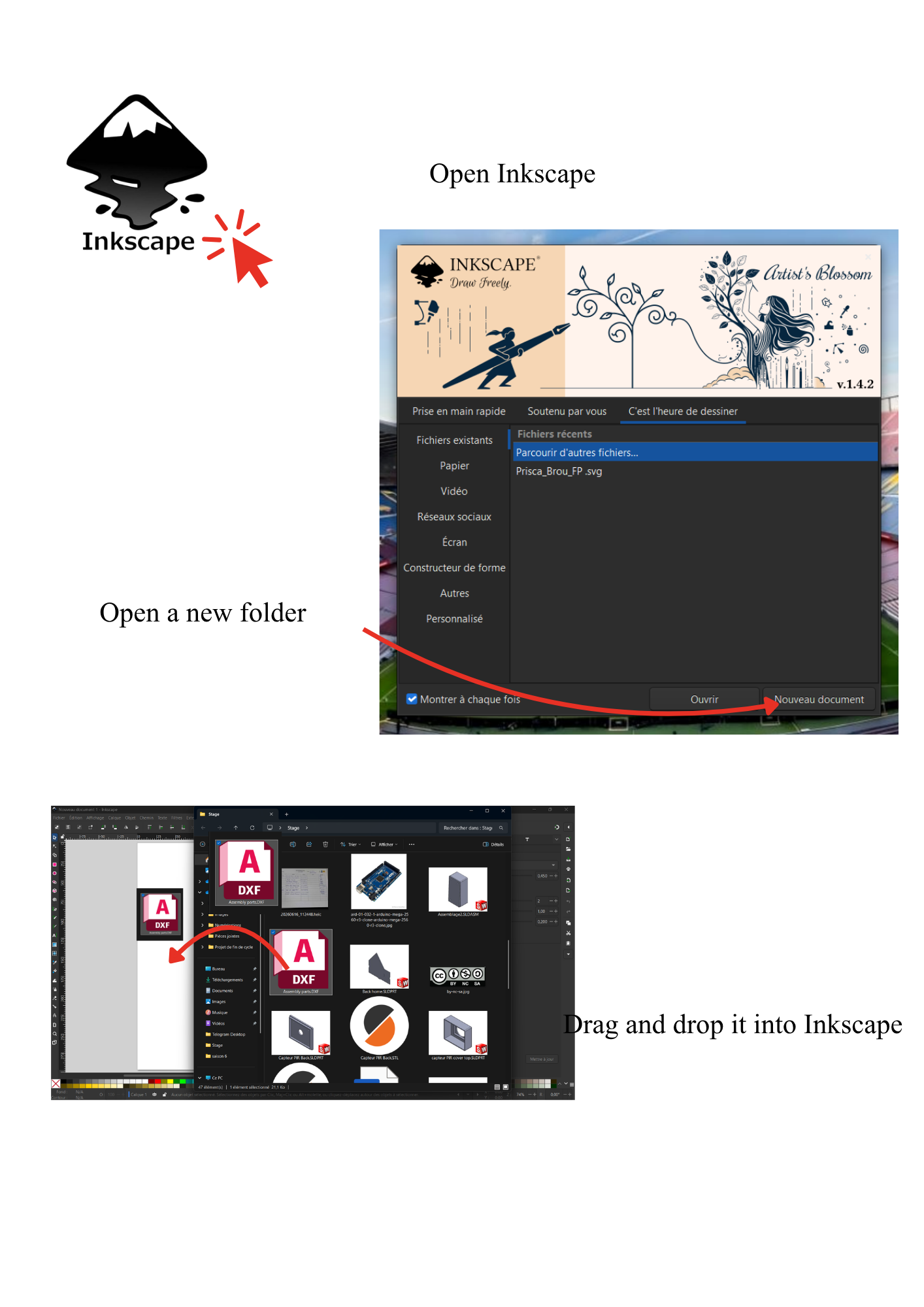
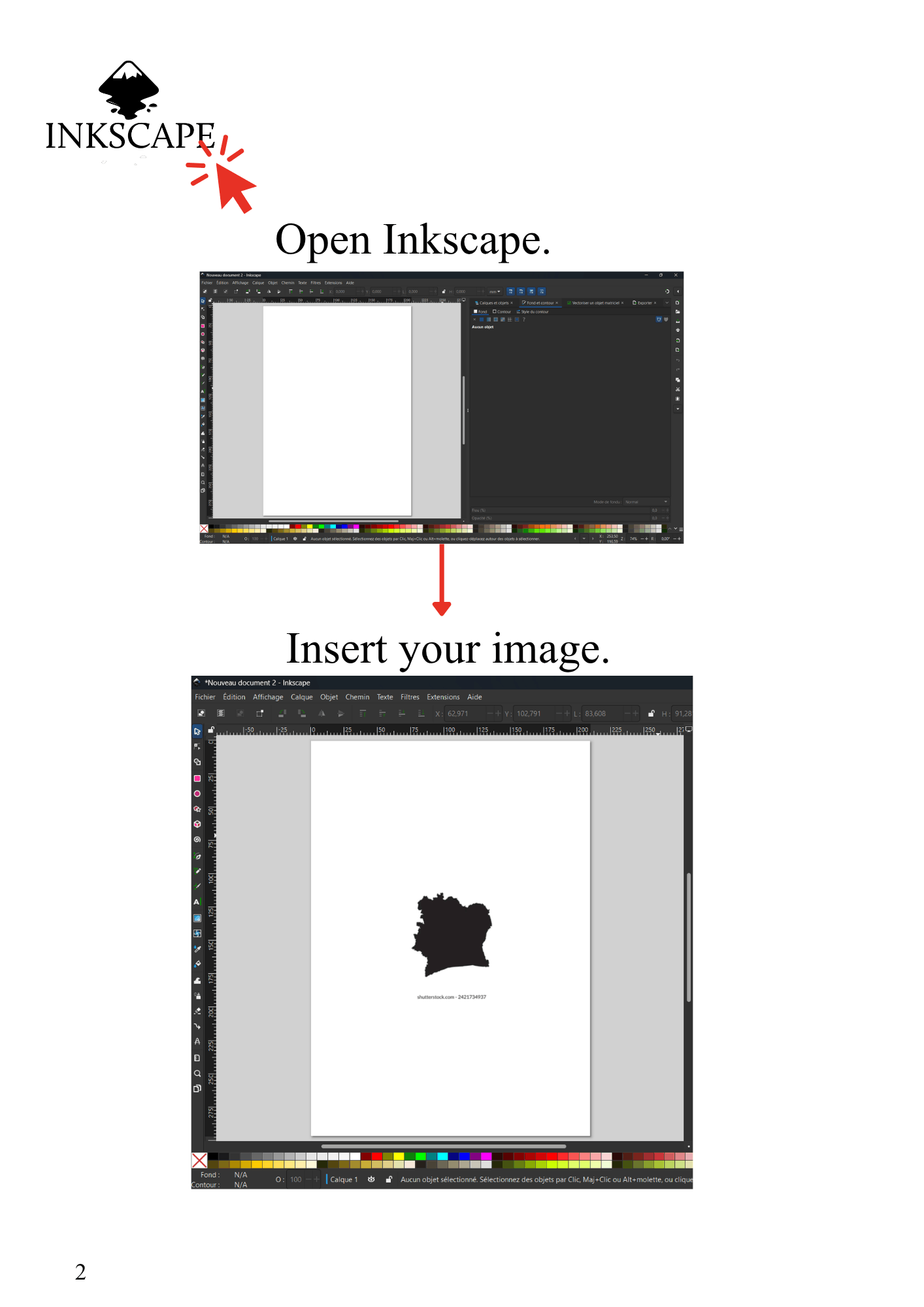
Step 9: Open Inkscape
- Open Inkscape.
- Create a new document.
- Drag and drop the DXF file into the workspace.
Step 10: Prepare the Layout
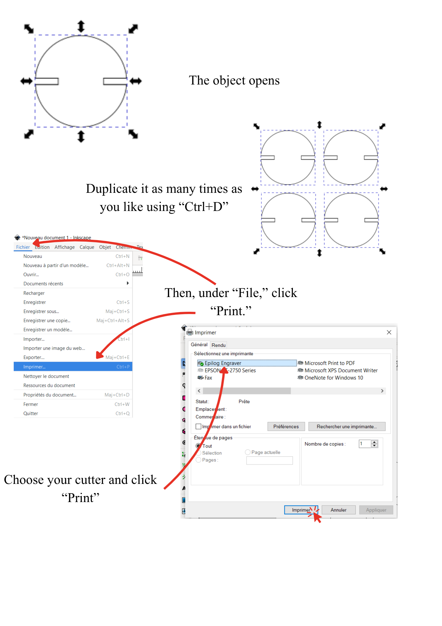
- The part appears in the workspace.
- Press Ctrl + D to duplicate it as many times as needed.
- Click File.
- Select Print.
- Choose your cutting machine.
- Click Print.
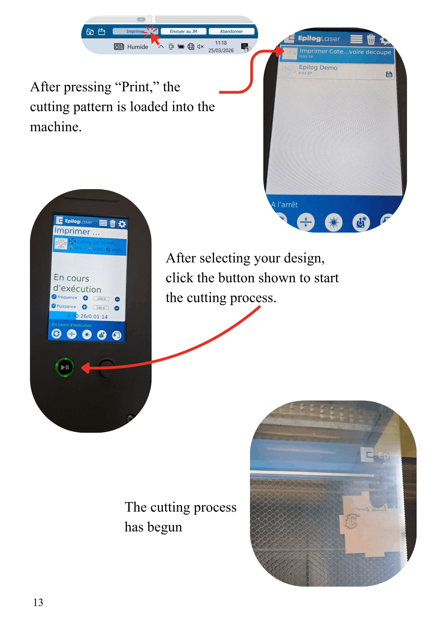
Step 11: Start the Cutting Process
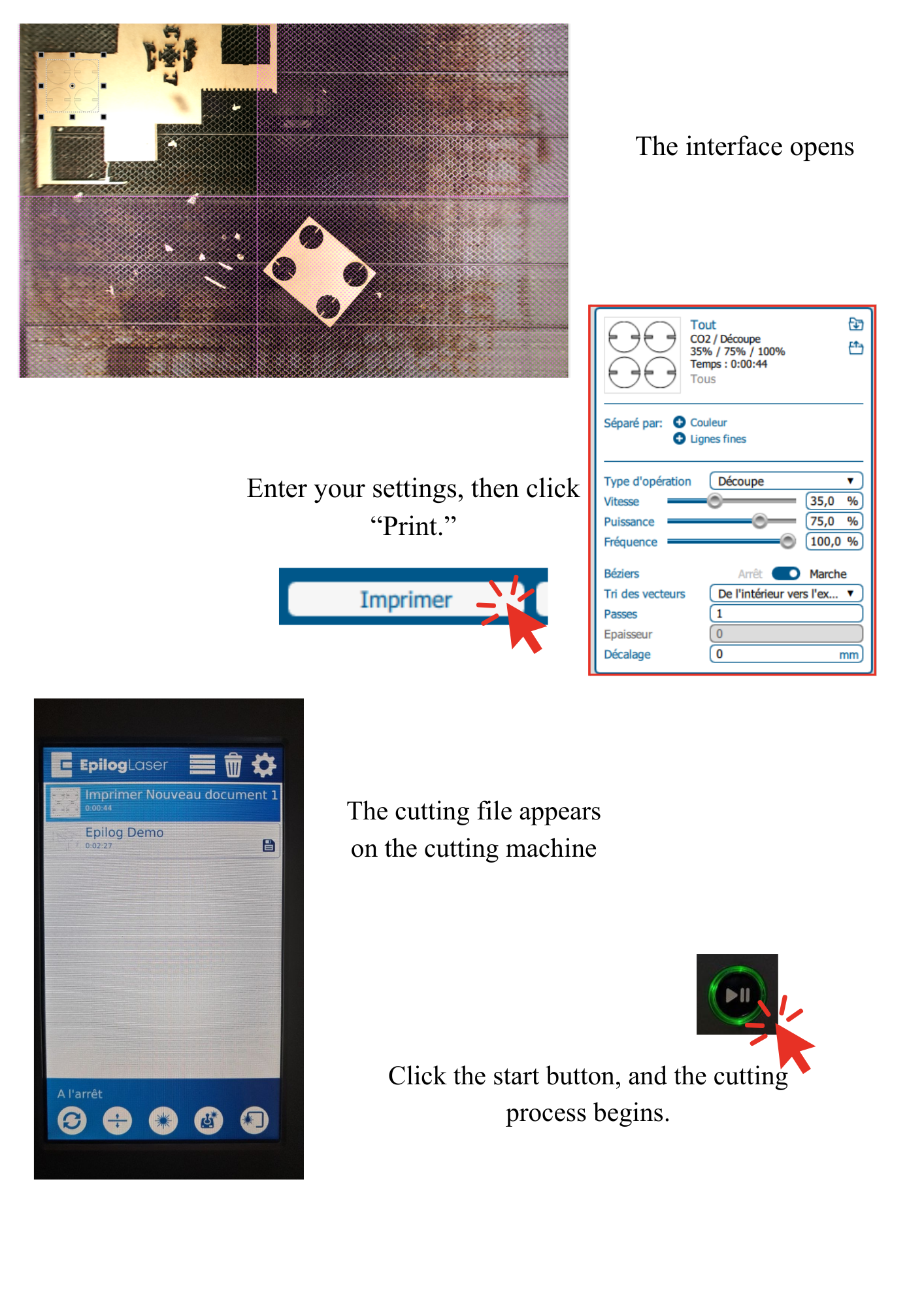
- The cutting interface opens.
- Enter the required settings.
- Click Print.
- The cutting file is sent to the machine.
- Press the Start button to begin the cutting process.
Step 12: Final Result
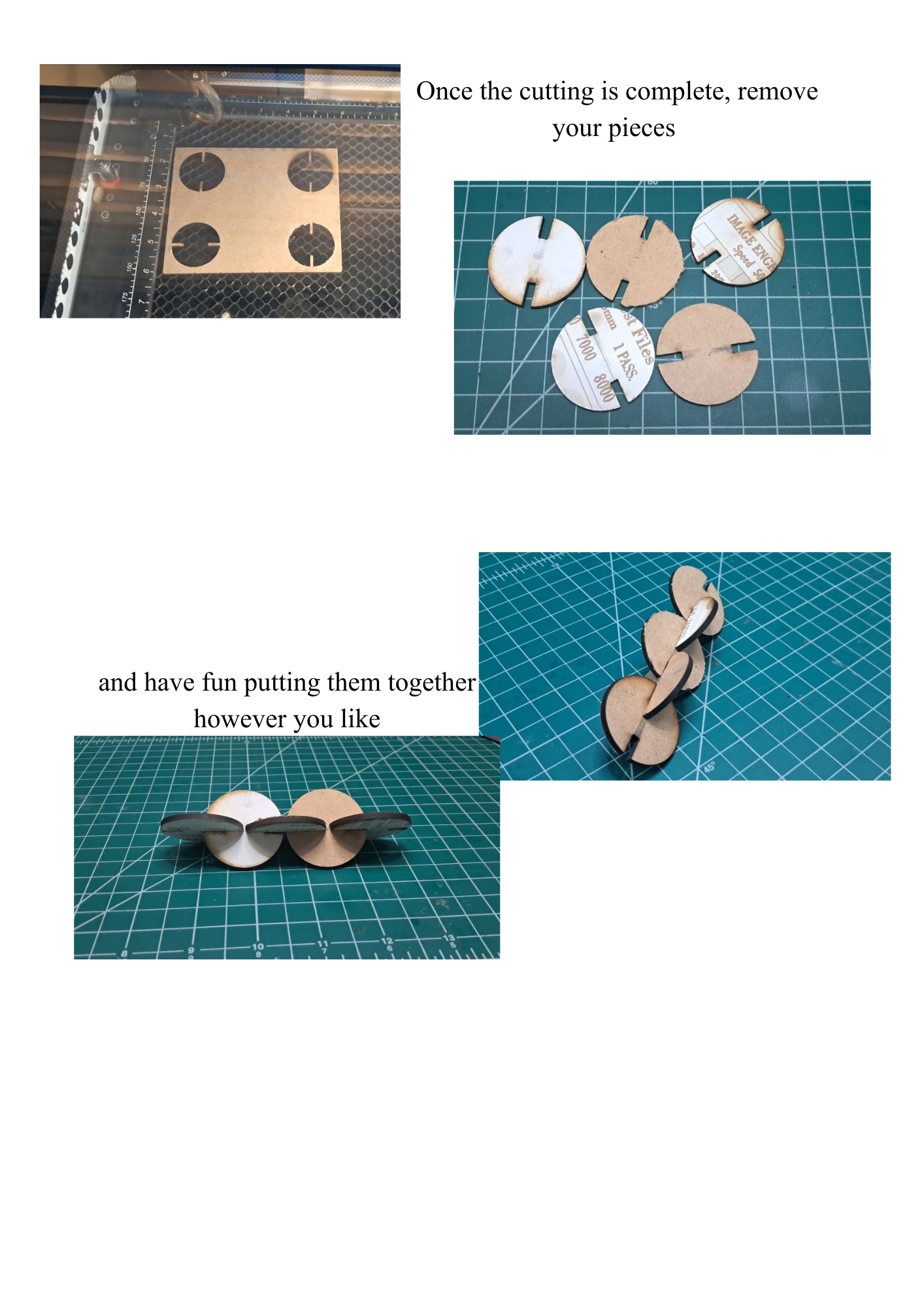
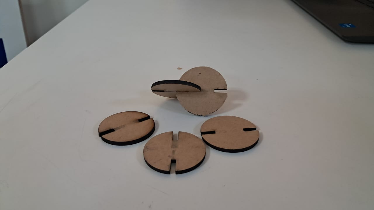
- Once the cutting process is complete, remove the pieces.
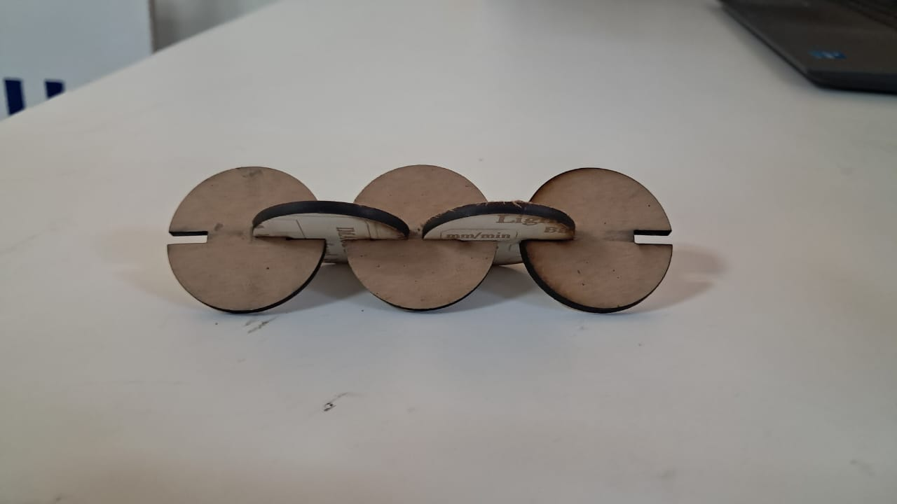
- Assemble them as desired.


Step 1 : Image Preparation : download the map image from Google
- Open Google
- Choose an image
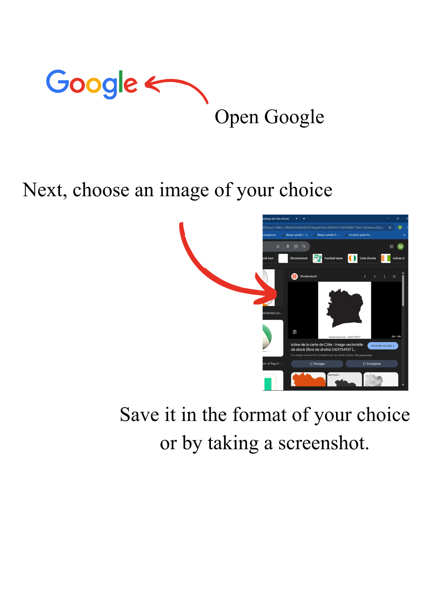
Step 2 : Vectorization with Inkscape
A Import Image from folder to Inkscape
- Open Inkscape
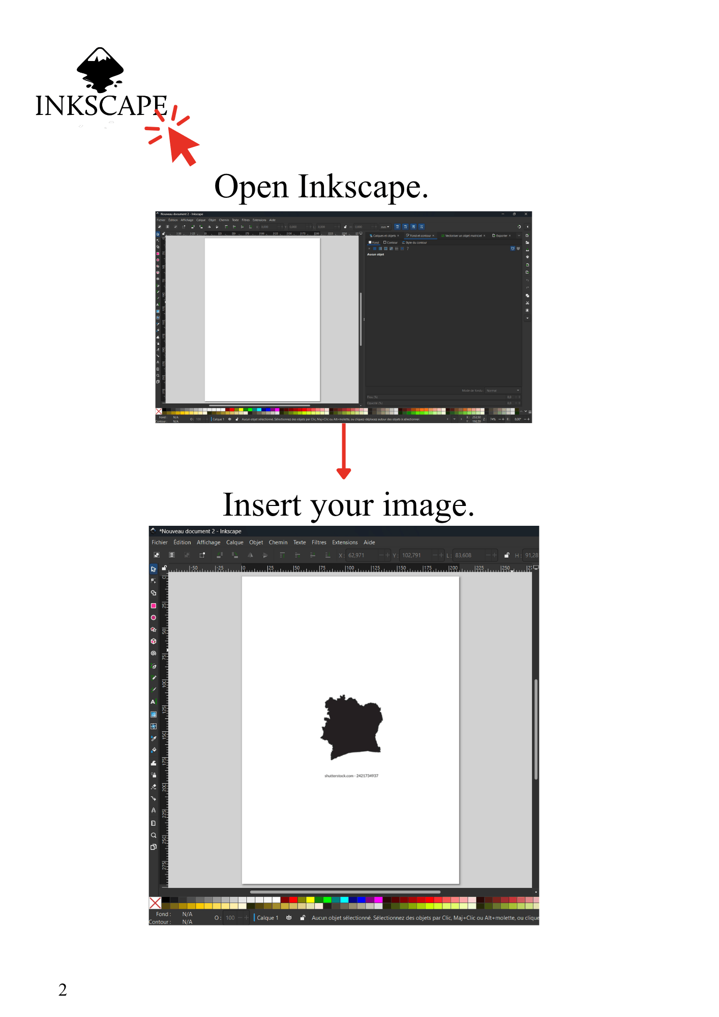
B Convert to Vector
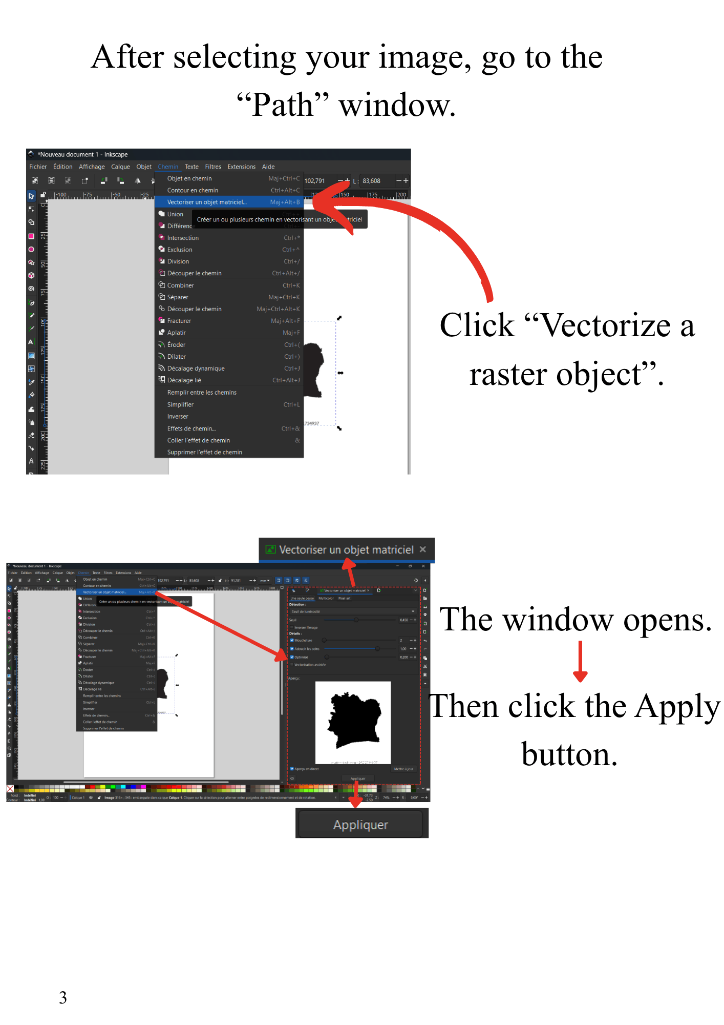
- Go to Path → Trace Bitmap
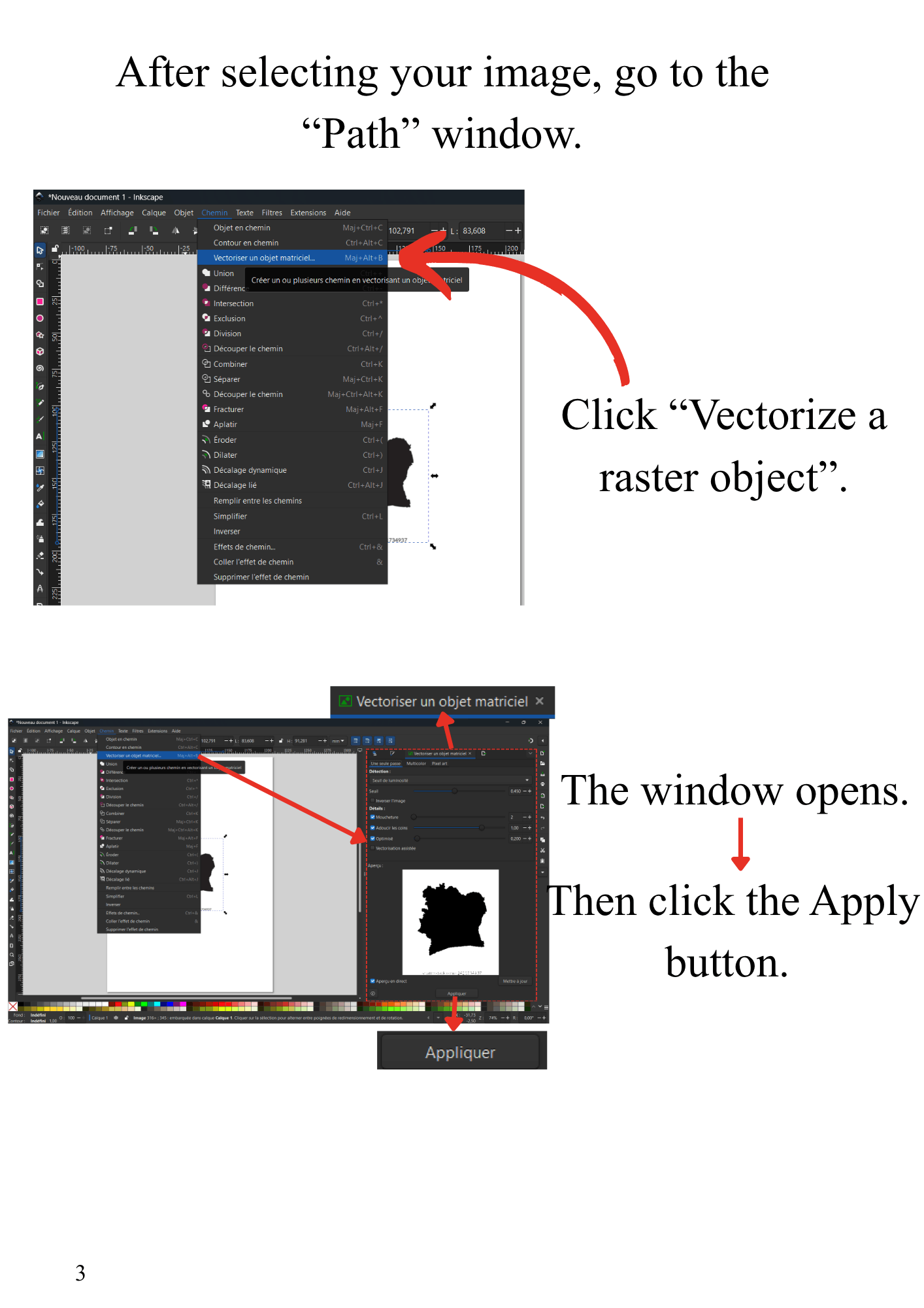
C Clean the Image
- Remove the background
D Create Assembly Features for contrain making
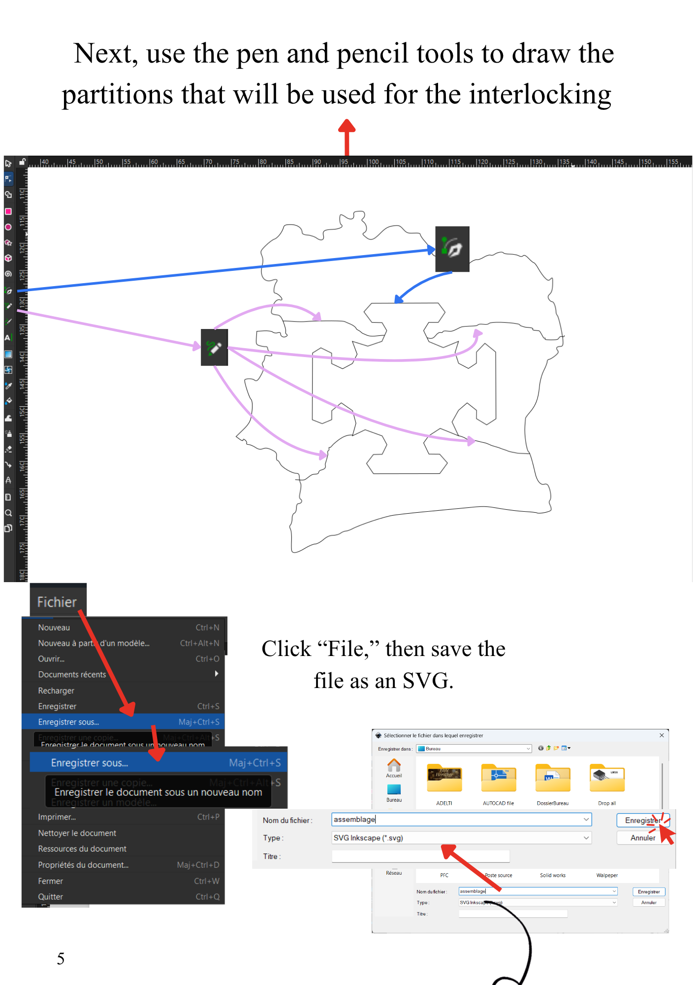
i can cut but i have to make a parametric , so that continue with AUTOCAD
Step 3 : Processing in AutoCAD
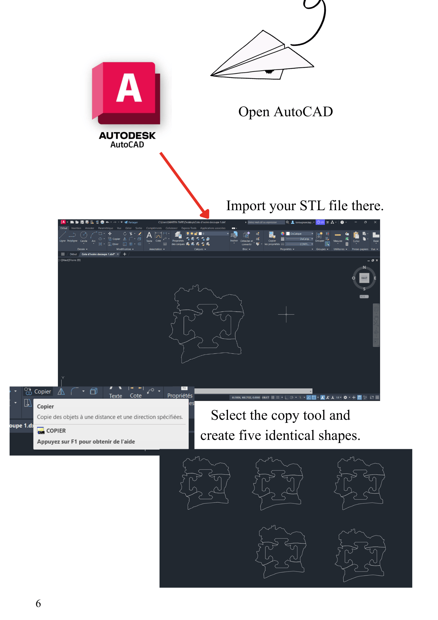
Import & Duplicate
- Import your file
- Use copy tool → create 5 identical shapes
Adjust Geometry
.png)
Step 4 : Understanding Clearance
A - What is Clearance?
Clearance is the space between two parts to ensure proper assembly.
| Type | Description |
|---|---|
| Clearance Fit | Easy insertion |
| Zero Fit | Perfect adjustment |
| Tight Fit | Forced assembly |
B - Practical Case
- Base length: 1.77 cm
- Laser thickness: 0.2 mm this is our laser cutter kerf
- Adjustment: +0.1 mm
- Final clearance: 0.15 mm
Step 5 : Final Check in Inkscape
- Set stroke width to 0.2 mm

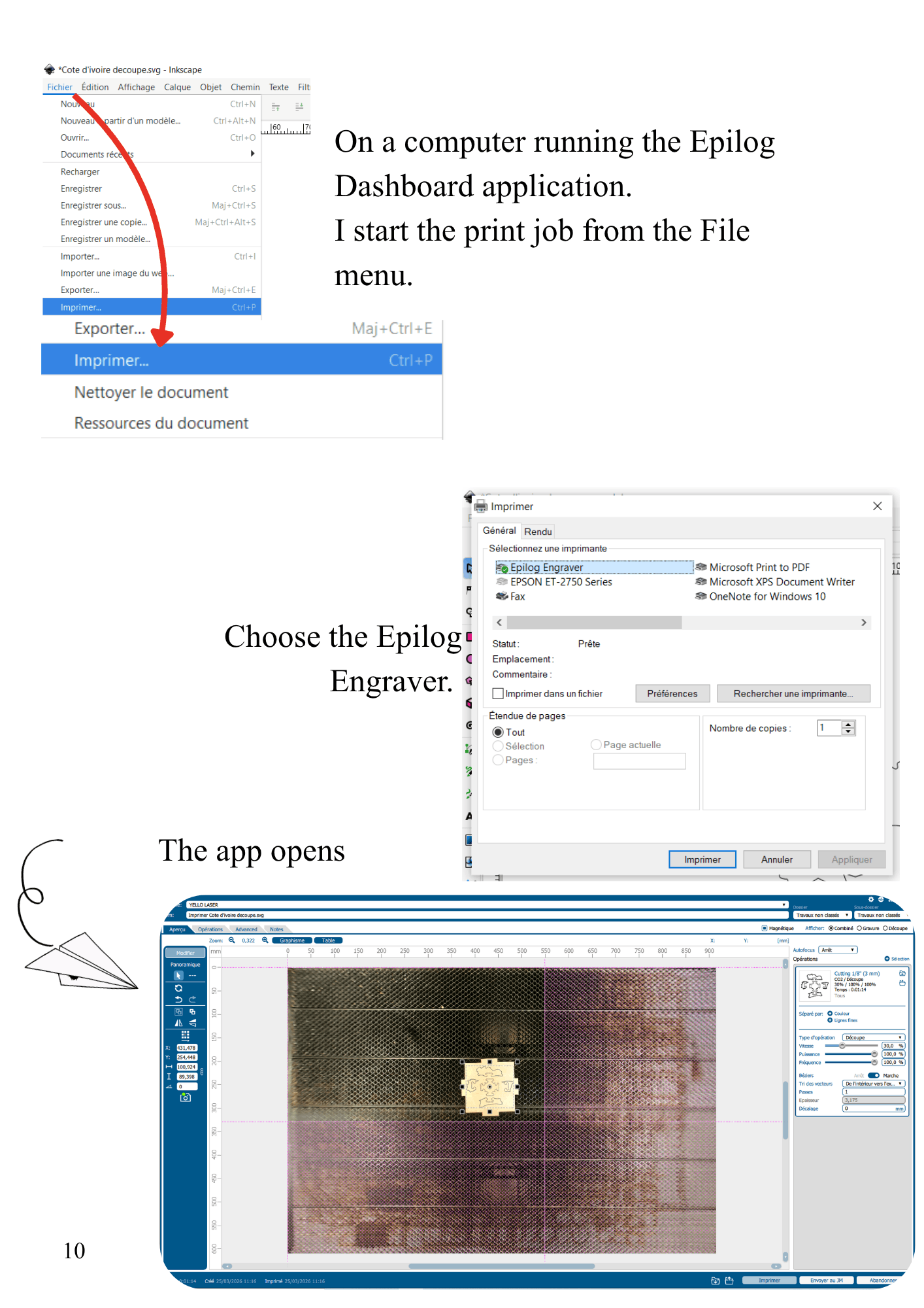
Step 6 : Epilog Dashboard Setup
.png)
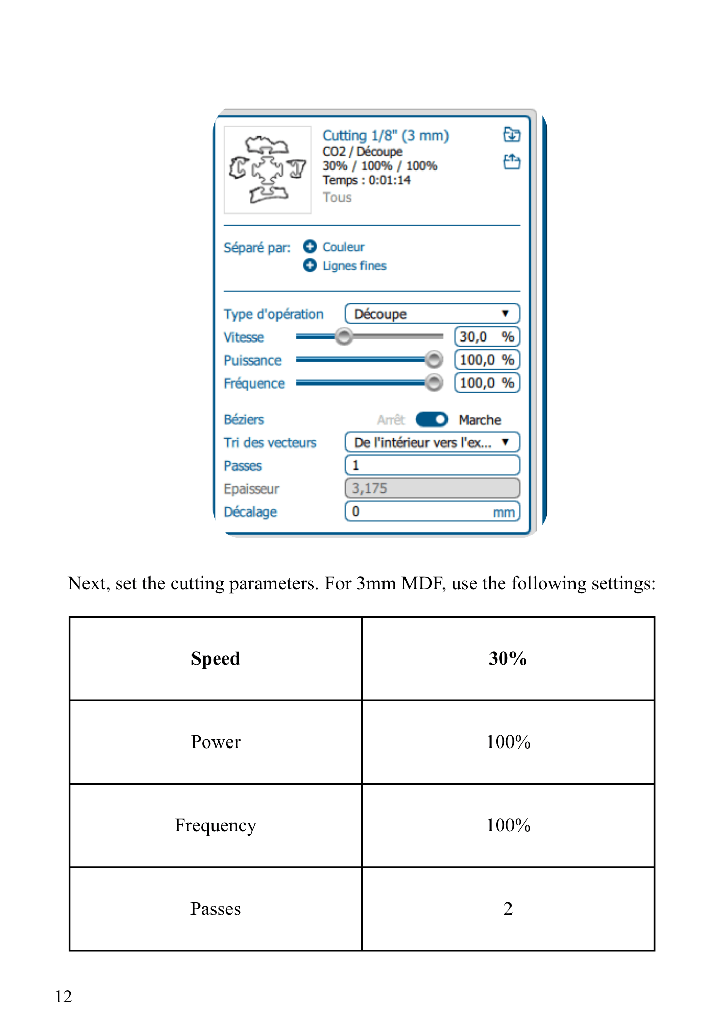
Step 7 : Cutting Parameters (3mm MDF)
| Parameter | Value |
|---|---|
| Speed | 30% |
| Power | 100% |
| Frequency | 100% |
Step 8 : Cutting Process
Final Result

Vinyl Sticker Creation
Overview
This guide explains how to create a vinyl sticker using Inkscape and Roland CutStudio.
Step 1 : Image Preparation
in this cas it is usefull to vectorize the file with inkscape
Step 2 — Vectorization with Inkscape
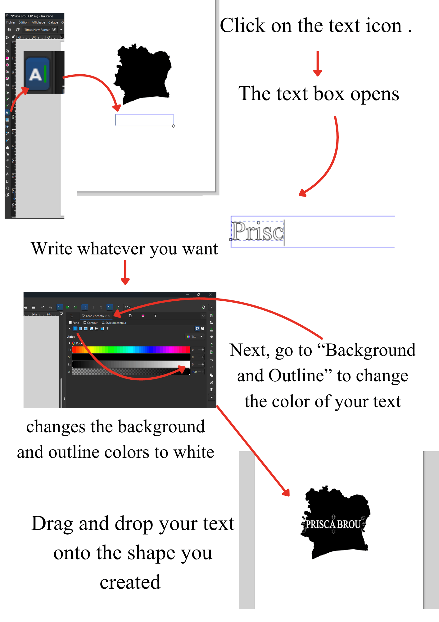
Step 3 : Add Text
Step 4 : Combine Elements
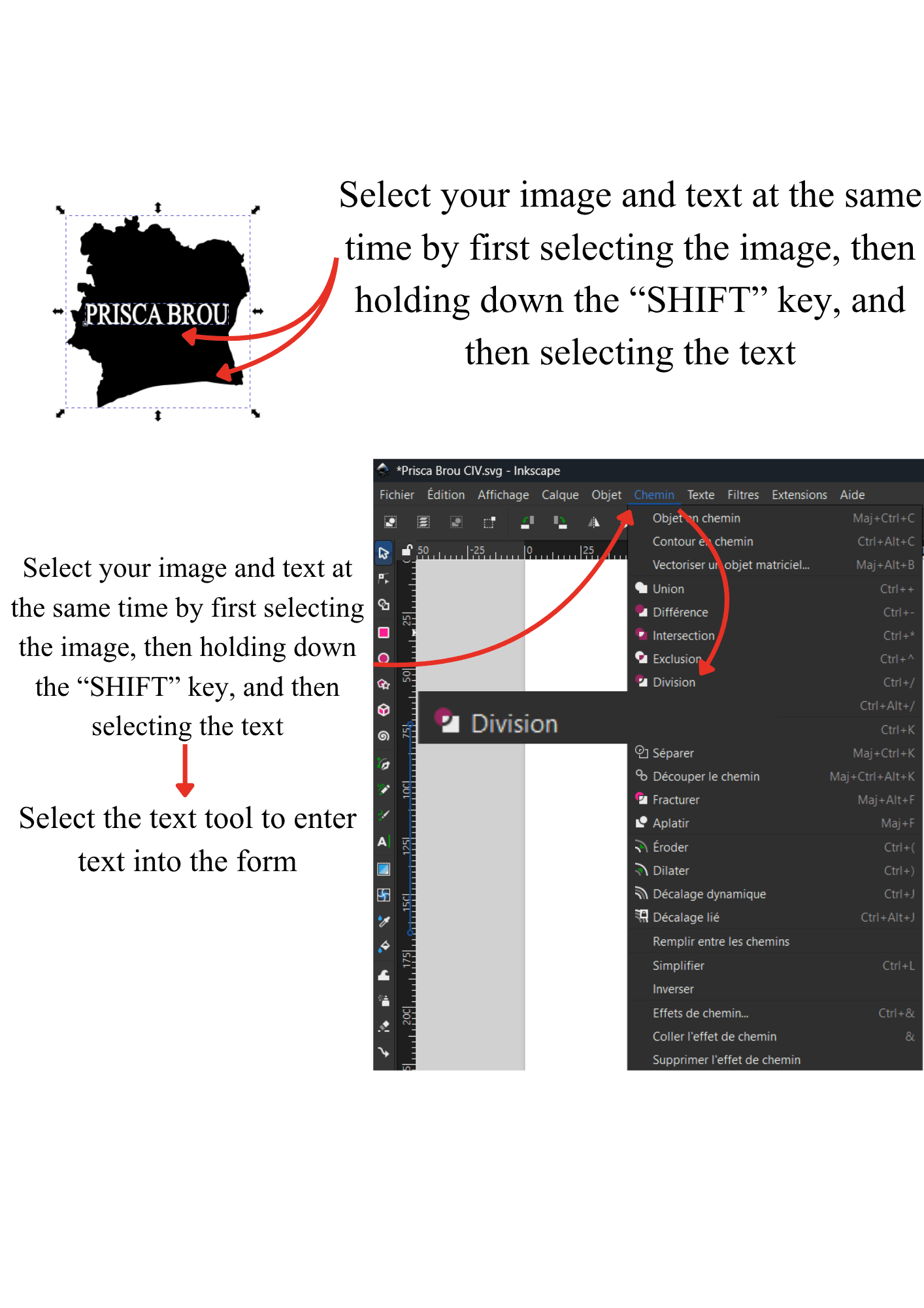
Step 5 : Open in Roland CutStudio
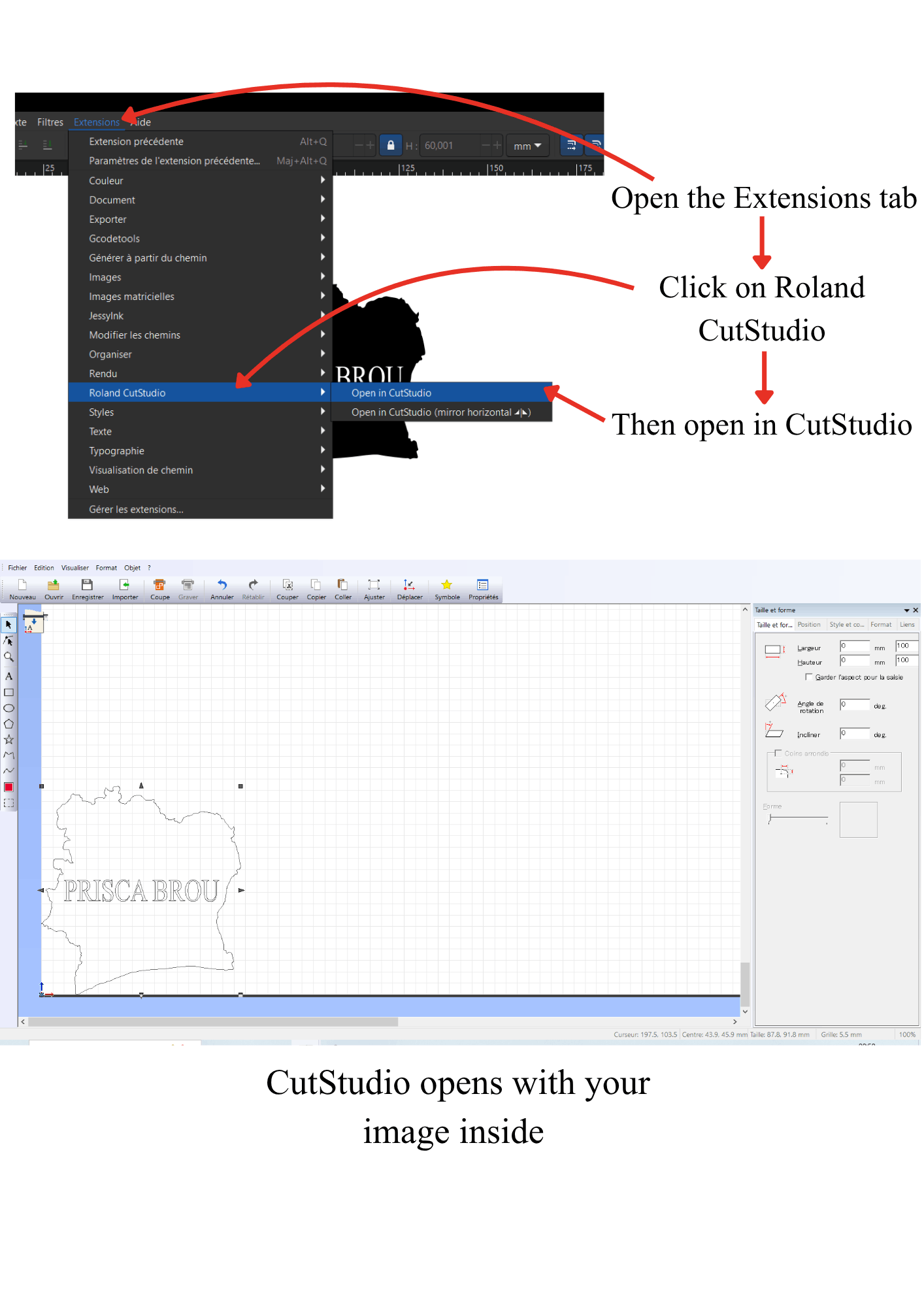
Step 6 : Cutting Settings
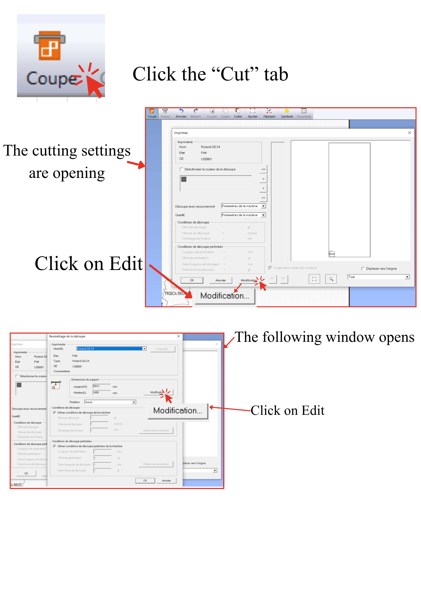
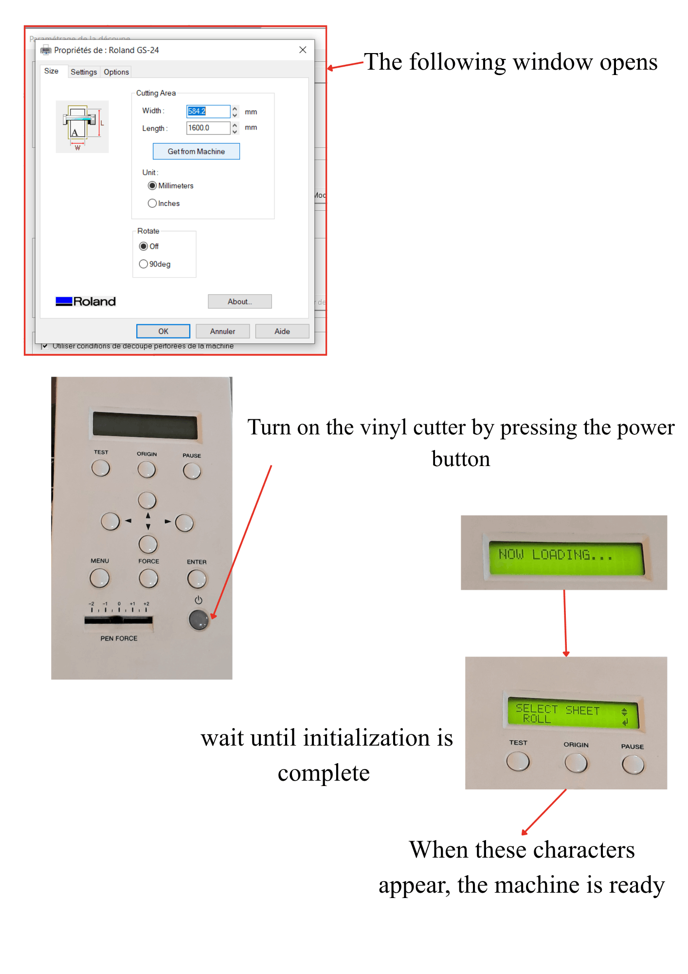
Step 7 : Download Machine Settings
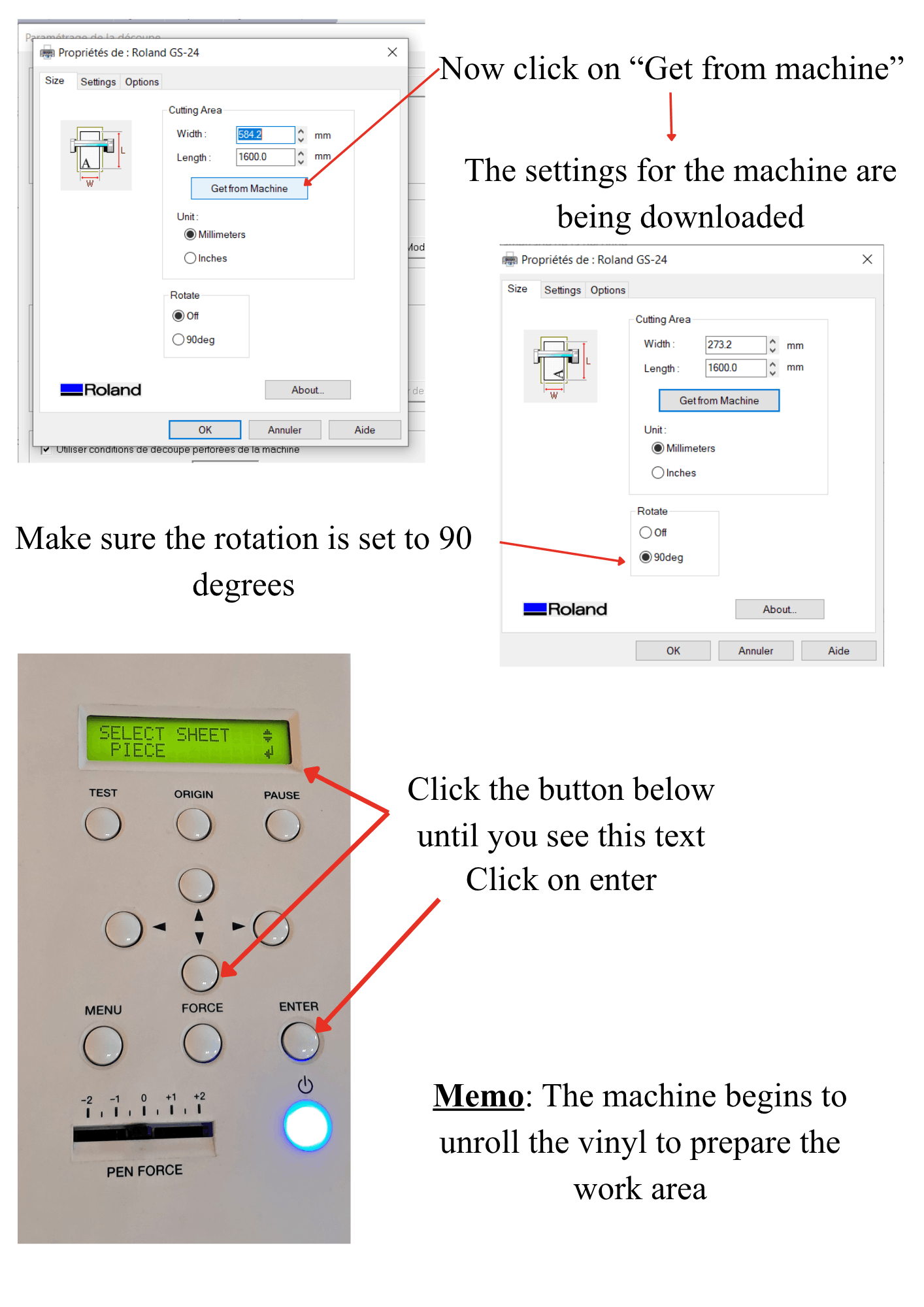
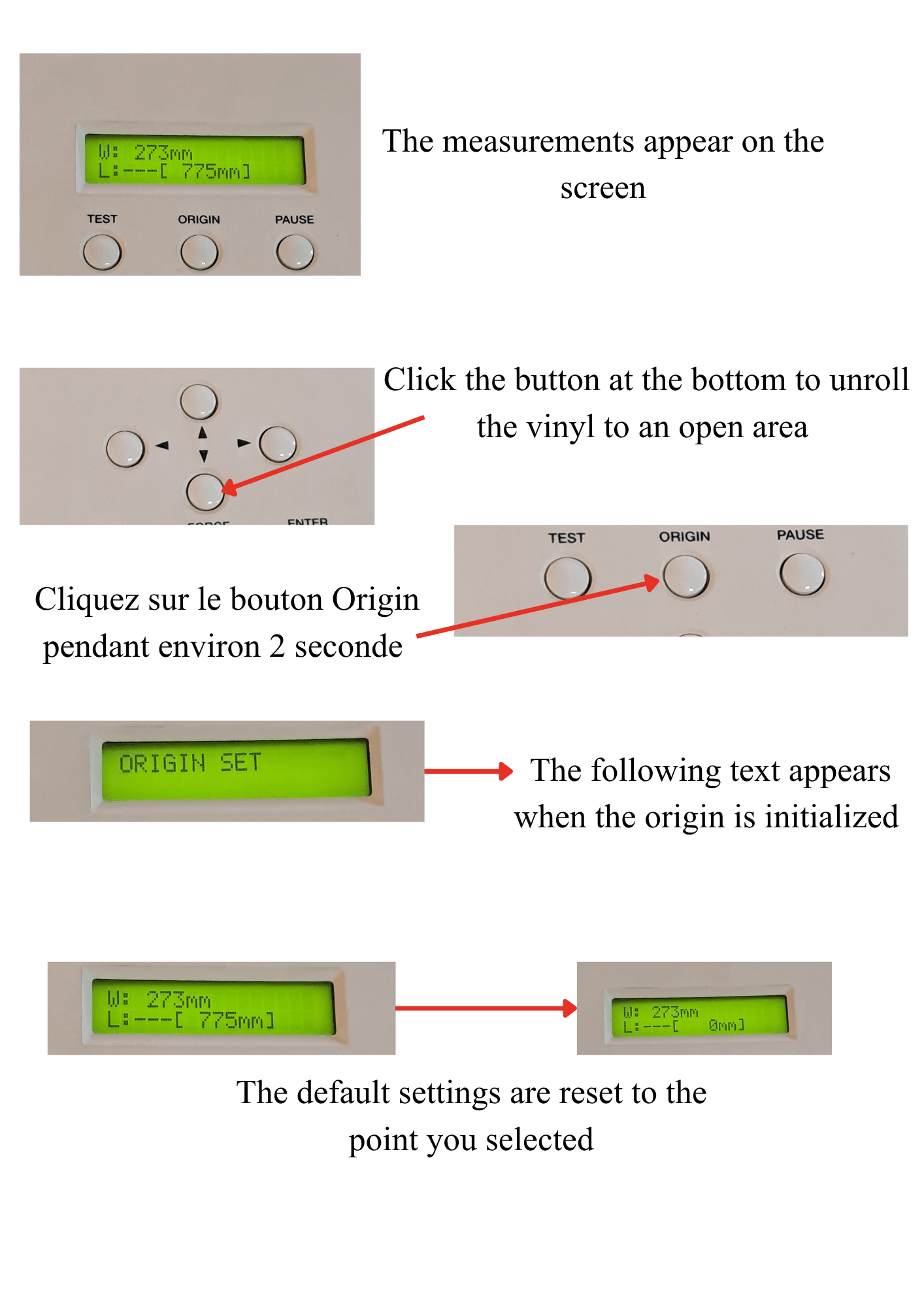
Step 8 : Set the Origin
Step 9 : Align the Design
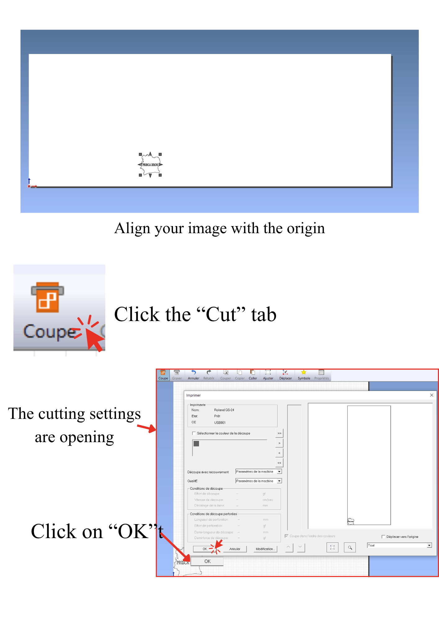
Step 10 : Cutting Process
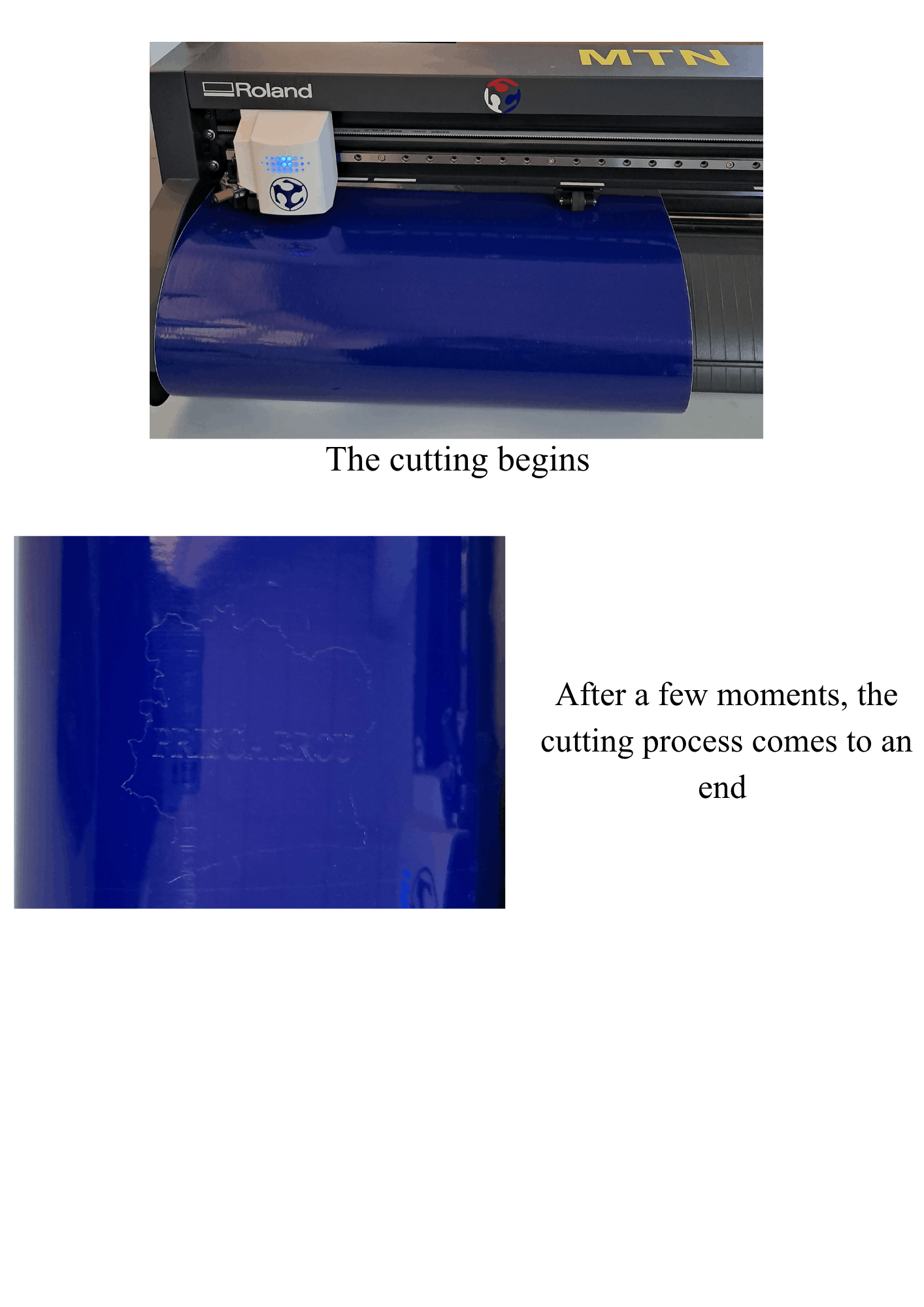
Step 11 : Weeding the Vinyl
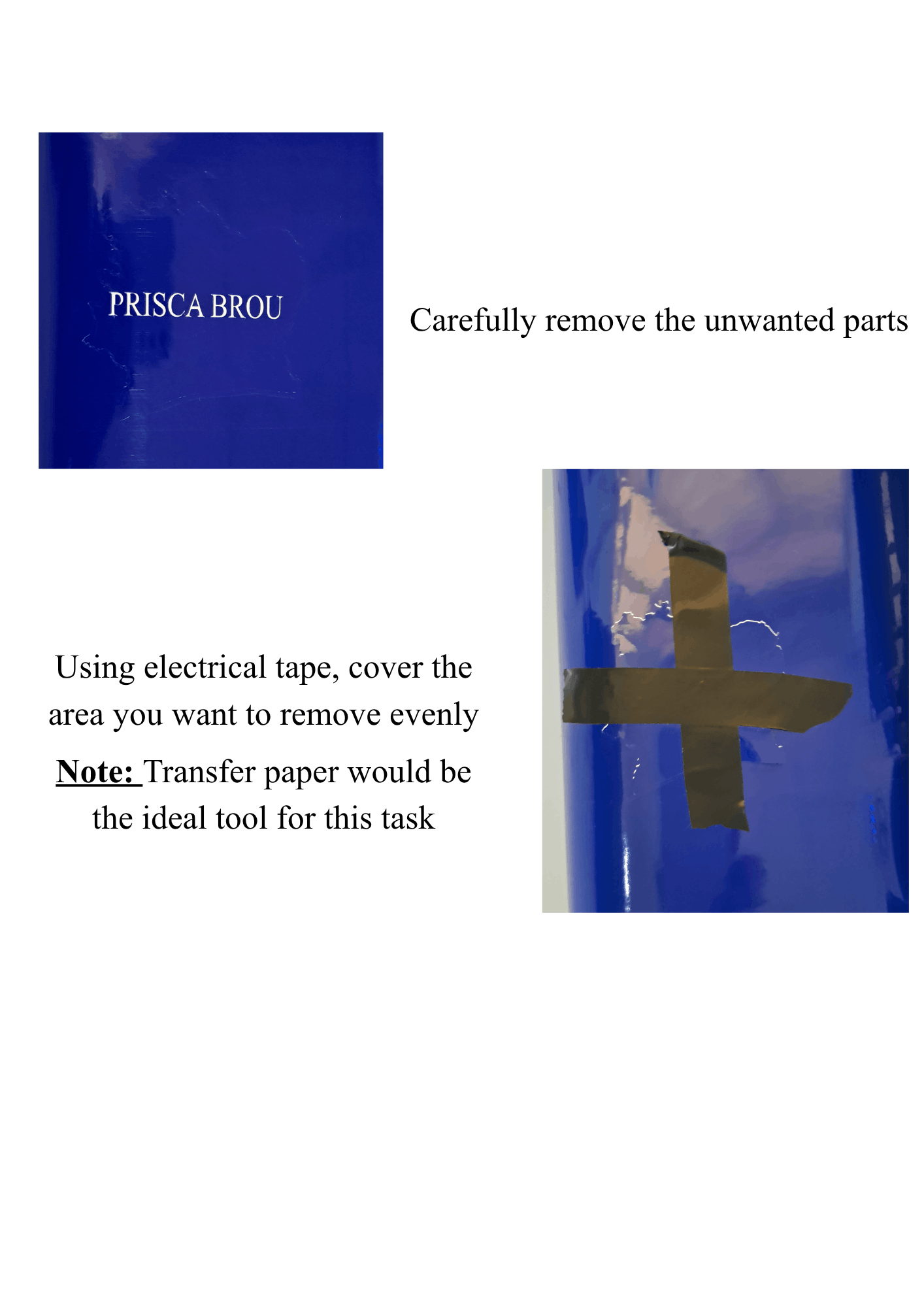
Step 12 : Apply the Sticker
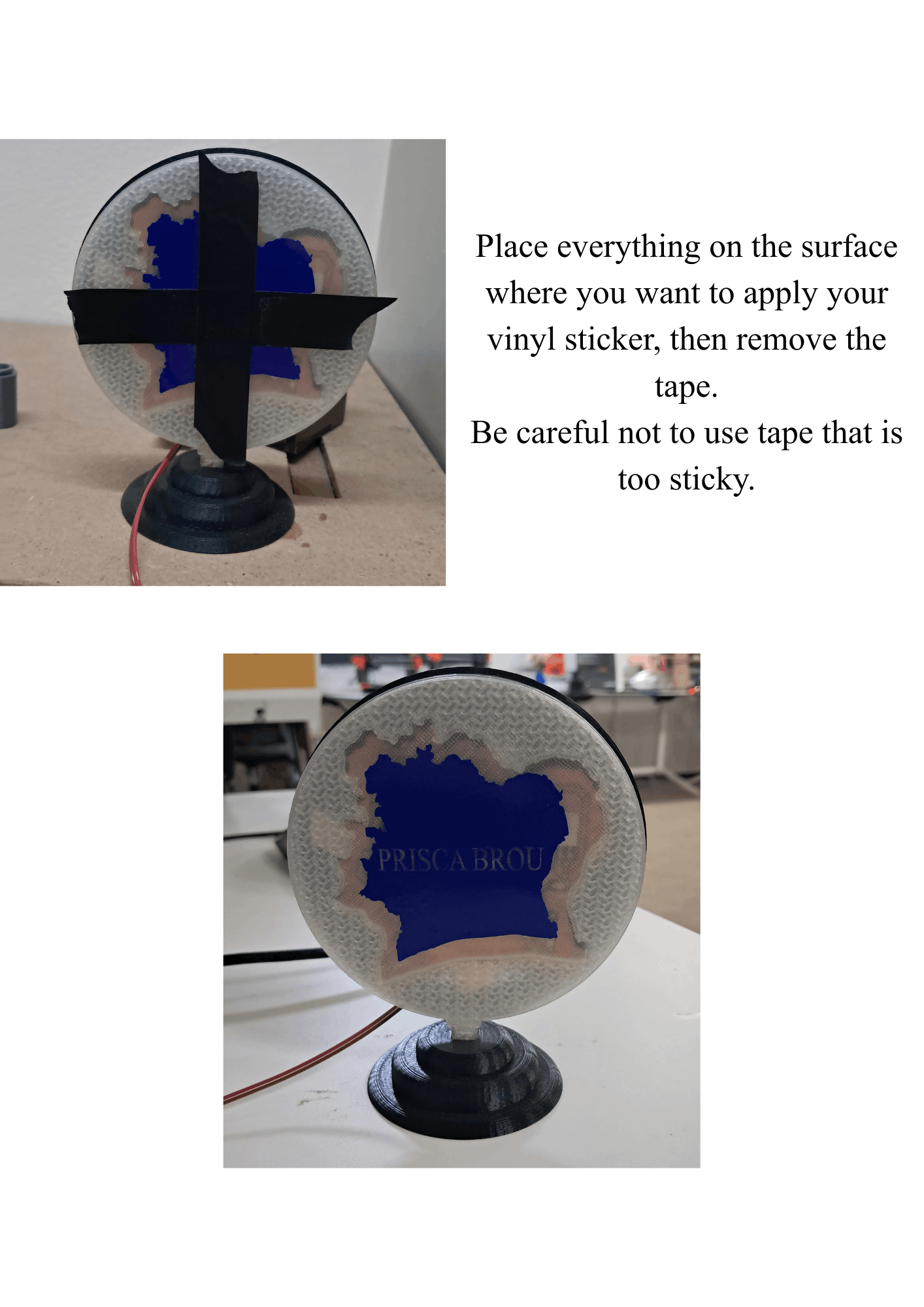
Final Result
Your custom vinyl sticker is now complete!