11. Networking and communications
Group assignment:
- Send a message between two projects
To see our group assignment click here
Individual assignment:
- Design, build, and connect wired or wireless node(s) with network or bus addresses
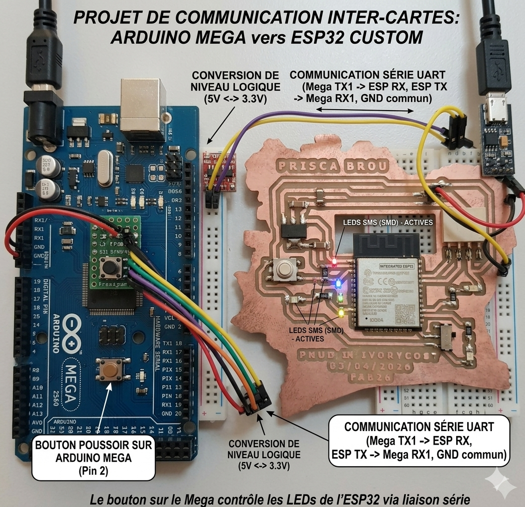
MEGA 2560 ↔ ESP32
Interactive Training Project

Introduction
Welcome to this embedded systems communication project using:
- an Arduino Mega 2560;
- a custom ESP32 PCB;
- LEDs;
- and a push button.
In this training exercise, you will learn how to:
- establish UART communication between two microcontrollers;
- control LEDs remotely;
- create different lighting sequences;
- manage push button interactions;
- and understand serial communication basics.
1. Project Overview
The Arduino Mega acts as the master controller.
The ESP32 acts as the LED control module.
When the push button is pressed:
- the Mega sends a serial command;
- the ESP32 receives the command;
- and executes the corresponding LED animation.
2. Hardware Presentation
Arduino Mega 2560
The Mega is responsible for:
- reading the push button state;
- changing operating modes;
- sending UART commands to the ESP32.
ESP32 Custom PCB
The ESP32 board is responsible for:
- receiving UART data;
- controlling the LEDs;
- executing lighting sequences.
Your custom PCB includes:
- ESP32-WROOM module;
- integrated LEDs;
- power switch;
- UART connector;
- reset / control button.
3. Wiring the Push Button
Connection Table
| Connection | Description |
|---|---|
| D2 | Push button signal |
| GND | Ground |
How It Works
The button uses the internal pull-up resistor:
This means:
| Button State | Electrical State |
|---|---|
| Released | HIGH |
| Pressed | LOW |
4. UART Communication
Serial Link Between Boards
| Arduino Mega | ESP32 |
|---|---|
| TX1 (18) | RX0 |
| RX1 (19) | TX0 |
| GND | GND |
Important UART Rule
The serial lines must always be crossed:
Why Use UART?
UART communication allows:
- microcontroller-to-microcontroller communication;
- sensor sharing;
- remote LED control;
- data exchange;
- wireless gateway creation.
5. ESP32 LED Configuration
LED Assignment
| LED | GPIO | Physical Pin |
|---|---|---|
| LED1 (red) | GPIO16 | 27 |
| LED2 (yellow) | GPIO17 | 28 |
| LED3 (green) | GPIO26 | 11 |
6. Sequence Logic
Mode 1 — Chained Sequence
Visual Effect
This allowed us to do:- sequential timing;
- digital output control;
- delay management.
Mode 2 — Synchronized Blink
Visual Effect
This allowed us to do:
- simultaneous GPIO control;
- repetitive loops;
- synchronized timing.
7. Operating Principle
| Button Press | Result |
|---|---|
| 1st press | Chained sequence |
| 2nd press | All LEDs blink together |
| 3rd press | Return to mode 1 |
| Next presses | Repeat cycle |
8. Arduino Mega Program
Role of the Program
The Mega program:
- detects button presses;
- changes operating modes;
- sends UART commands to the ESP32.
Arduino Mega Code
const int bouton = 2;

bool mode = false;

unsigned long lastPress = 0;

void setup() {

  pinMode(bouton, INPUT_PULLUP);

  Serial1.begin(9600);
}

void loop() {

  if(digitalRead(bouton) == LOW &&
     millis() - lastPress > 300) {

    mode = !mode;

    if(mode) {

      Serial1.write('B');
    }
    else {

      Serial1.write('A');
    }

    lastPress = millis();
  }
}
9. Understanding the Mega Code
Anti-Bounce Protection
This prevents:
- multiple unwanted detections;
- noisy button transitions.
Mode Switching
This instruction toggles between:
- mode 1;
- and mode 2.
10. ESP32 Program
Role of the ESP32
The ESP32:
- waits for UART commands;
- decodes received characters;
- executes LED sequences.
ESP32 Code
const int led1 = 16;
const int led2 = 17;
const int led3 = 26;

void setup() {

  Serial.begin(9600);

  pinMode(led1, OUTPUT);
  pinMode(led2, OUTPUT);
  pinMode(led3, OUTPUT);
}

void sequenceChaine() {

  digitalWrite(led1, HIGH);
  delay(200);
  digitalWrite(led1, LOW);

  digitalWrite(led2, HIGH);
  delay(200);
  digitalWrite(led2, LOW);

  digitalWrite(led3, HIGH);
  delay(200);
  digitalWrite(led3, LOW);
}

void sequenceBlink() {

  for(int i = 0; i < 5; i++) {

    digitalWrite(led1, HIGH);
    digitalWrite(led2, HIGH);
    digitalWrite(led3, HIGH);

    delay(300);

    digitalWrite(led1, LOW);
    digitalWrite(led2, LOW);
    digitalWrite(led3, LOW);

    delay(300);
  }
}

void loop() {

  if(Serial.available()) {

    char cmd = Serial.read();

    if(cmd == 'A') {

      sequenceChaine();
    }

    if(cmd == 'B') {

      sequenceBlink();
    }
  }
}
11. Upload Procedure
Before Uploading
Disconnect:
- TX;
- RX.
This prevents UART conflicts during programming.
Upload Sequence
12. Power Supply
Arduino Mega
| Method | Voltage |
|---|---|
| USB | 5V |
| DC Jack | 7V – 12V |
ESP32
| Method | Voltage |
|---|---|
| USB | 5V |
| VIN | External 5V |
13. Important Electrical Rule
Without a common ground:
- UART communication becomes unstable;
- data corruption may occur.
14. Training Objectives
After completing this project, you should understand:
- UART serial communication;
- GPIO control;
- push button handling;
- timing and delays;
- multi-board architecture;
- master/slave communication systems.
15. Possible Improvements
You can later add:
- OLED display;
- DHT11 sensor;
- Wi-Fi communication;
- Home Assistant integration;
- Bluetooth control;
- relay modules;
- joystick navigation;
- MQTT communication.
16. Final System Architecture
Individual assignment:
- Design, build, and connect wired or wireless node(s) with network or bus addresses