Project Development
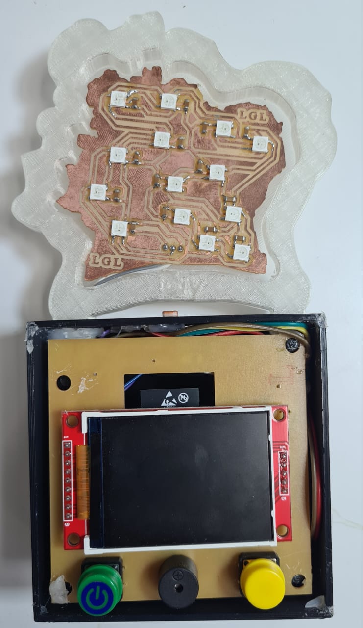
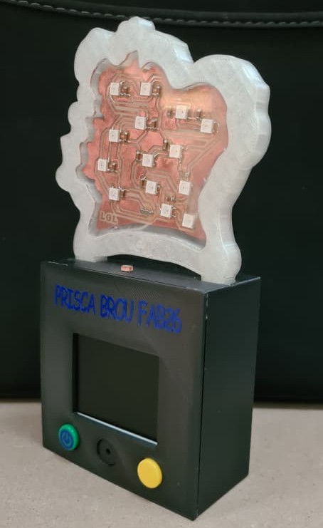
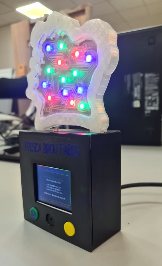 Front view of the finished device, showing the illuminated Côte d'Ivoire map panel alongside the base with the TFT clock display.
01. Sketch & System Architecture
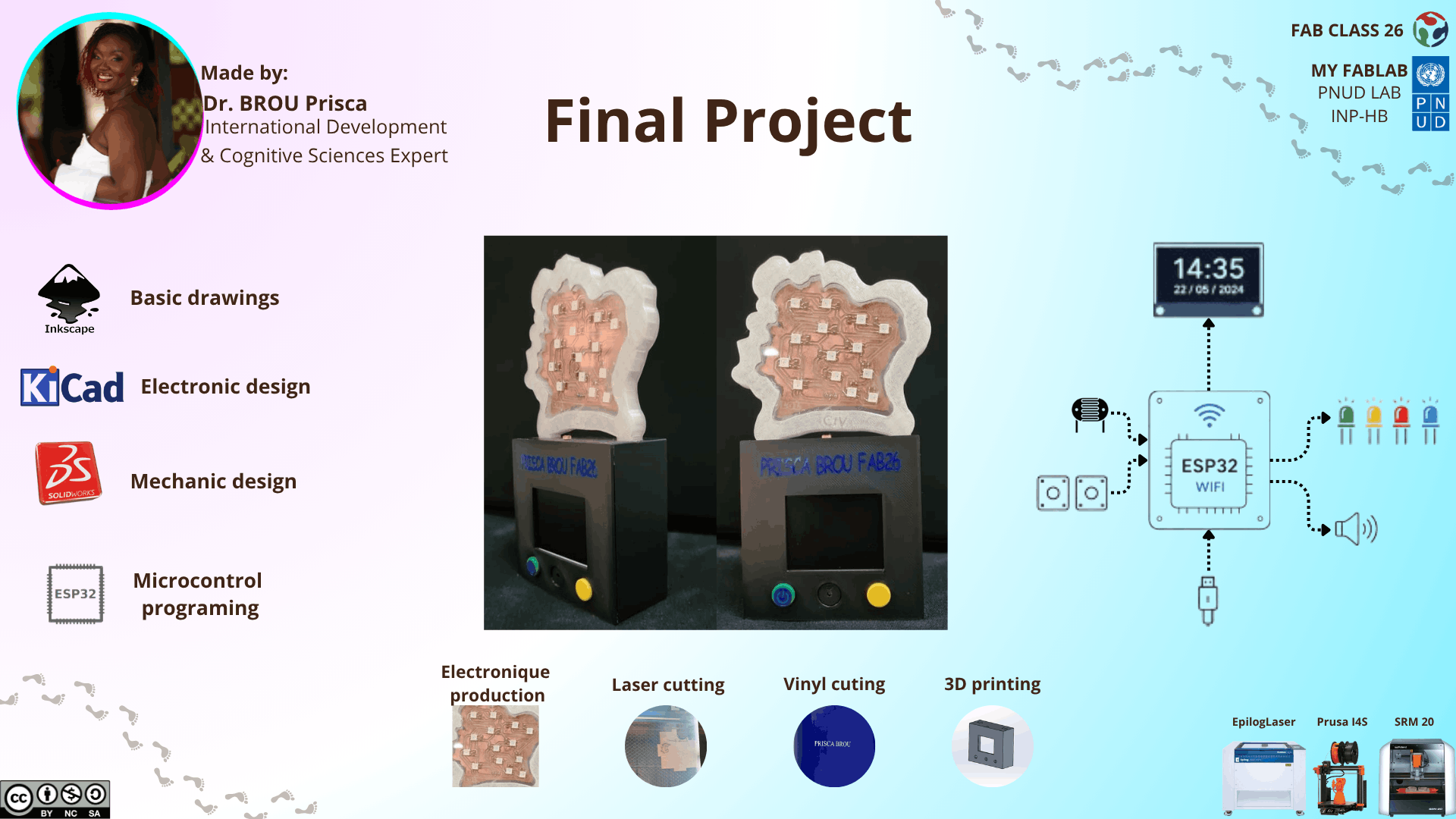 Concept sketch illustrating the two integrated layers of the system: the LED map panel (data visualization) and the base enclosure (timekeeping and controls).
The project was designed around two deeply integrated layers — data visualization and timekeeping — fused into a single physical artifact:
- The PCB map panel — a custom circuit board shaped as the map of Côte d'Ivoire, with RGB LEDs positioned at key UNDP intervention cities across the country, producing a geo-coded light display
- The base enclosure — a 3D-printed black box housing the ESP32 microcontroller, the TFT screen (real-time clock + date), and the interactive push buttons
The system is built around the ESP32 microcontroller, which simultaneously:
- Controls the RGB LEDs on the map PCB to visualize UNDP regional data
- Displays real-time clock and date on the TFT screen, powered by a hardware RTC module
- Reads input from the push buttons to switch display modes
- Hosts its own Wi-Fi access point, so time, alarms, and district status can be configured locally from a browser, with no internet connection required
02. Enclosure Design
For the 3D design of the device enclosure, I used SolidWorks.
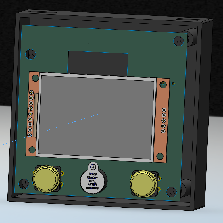
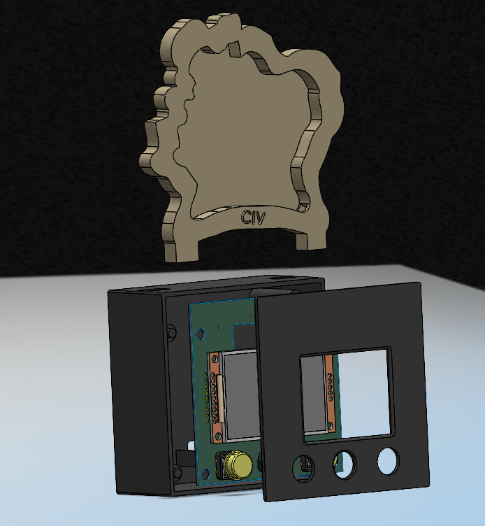 Top view of the enclosure base, showing the cutout for the TFT screen and the push button placement.
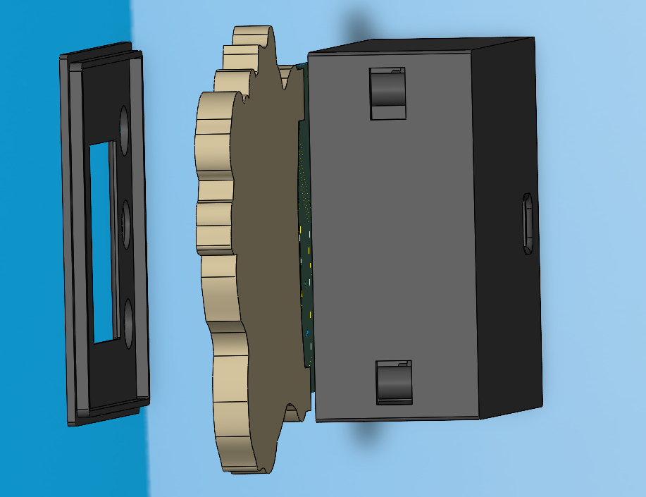 Front view of the enclosure with key dimensions annotated for the screen opening and button holes.
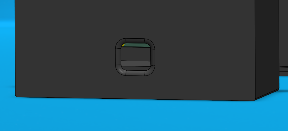 Side view showing the enclosure wall thickness and internal space reserved for cable routing.
 Bottom view of the enclosure, showing the access panel used for wiring and mounting the ESP32.
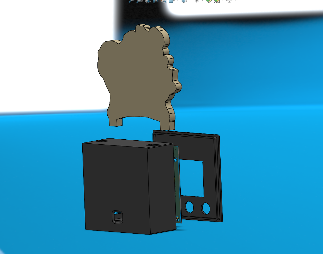
 Isometric render of the complete enclosure assembly, showing how the base and the trophy panel fit together.
The enclosure is made up of two parts:
- The base — a black box housing the ESP32, the TFT screen, and the push buttons
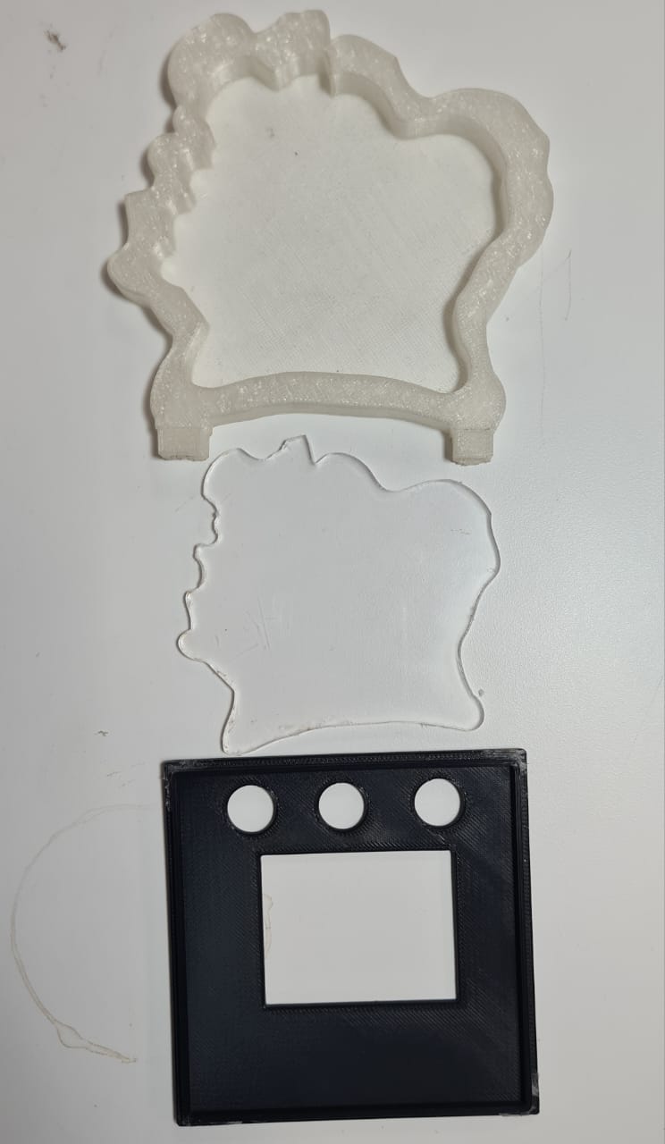
- The trophy panel — a translucent acrylic silhouette of Côte d'Ivoire holding the custom PCB
03. 3D Printing
The enclosure base was printed using the Prusa MK4S available in our FabLab.
Printing parameters used:
| Parameter | Value |
|---|---|
| Print setting | 0.20mm QUALITY |
| Filament | PLA |
| Supports | Used on the main shell only |
| Infill | 20% |
For more details on the 3D printing procedure, refer to Week 5 — 3D Scanning and Printing.
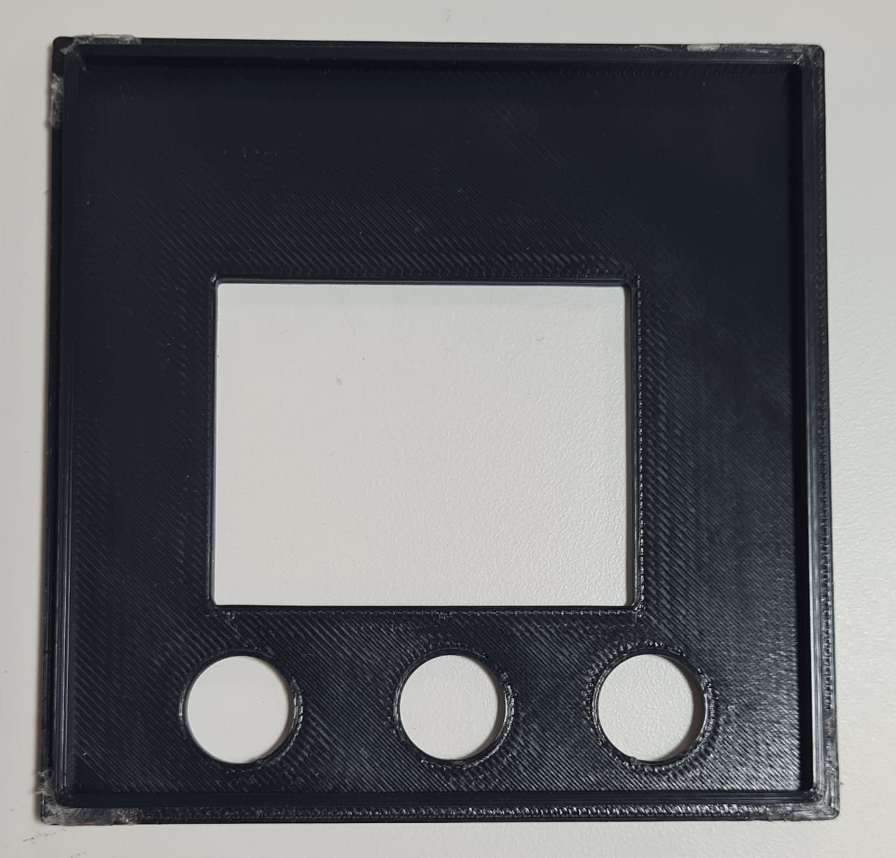 The Prusa MK4S printing the enclosure base, layer by layer.
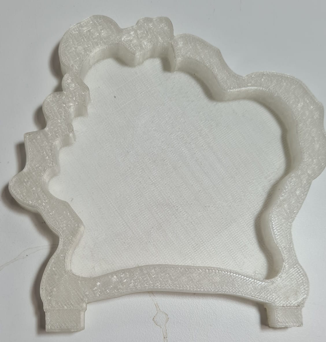 The finished 3D-printed base after support removal, ready for post-processing.
04. Laser Cutting & Vinyl Cutting
Laser Cutting — Côte d'Ivoire Silhouette
The trophy panel (the map silhouette) was cut from translucent acrylic using the Epilog Laser available in our FabLab.
For more details on the laser cutting procedure, refer to Week 3 — Computer Controlled Cutting.
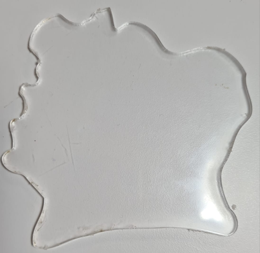 Laser cutting setup, with the translucent acrylic sheet positioned on the Epilog Laser bed.
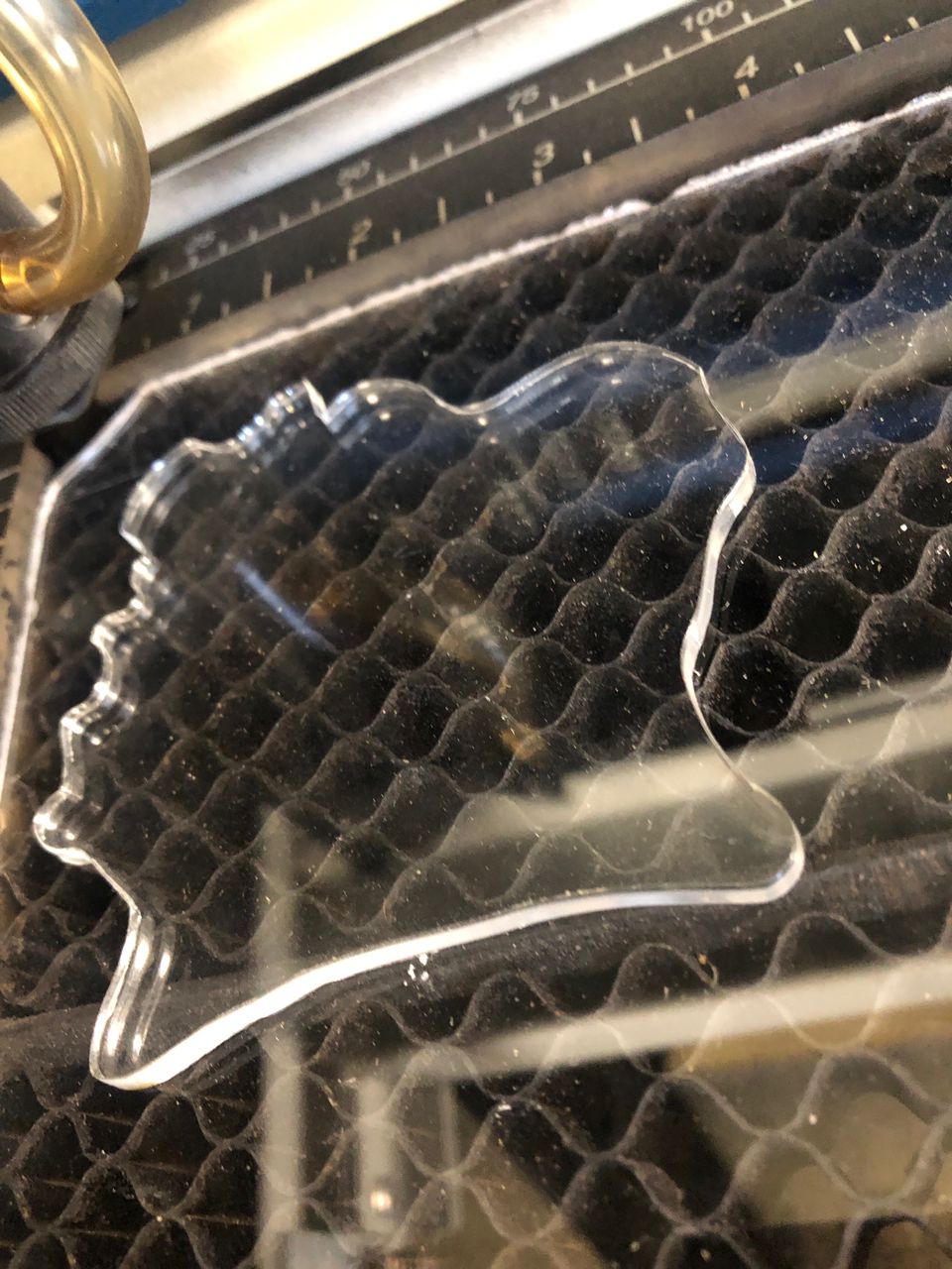 Laser cutting in progress, engraving the outline of the Côte d'Ivoire silhouette.
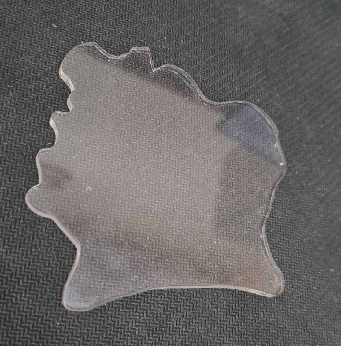 The finished laser-cut acrylic silhouette of Côte d'Ivoire, before final assembly.
Vinyl Cutting — Finishing Details
Vinyl cutting was used to add decorative finishing details to the panel surface.
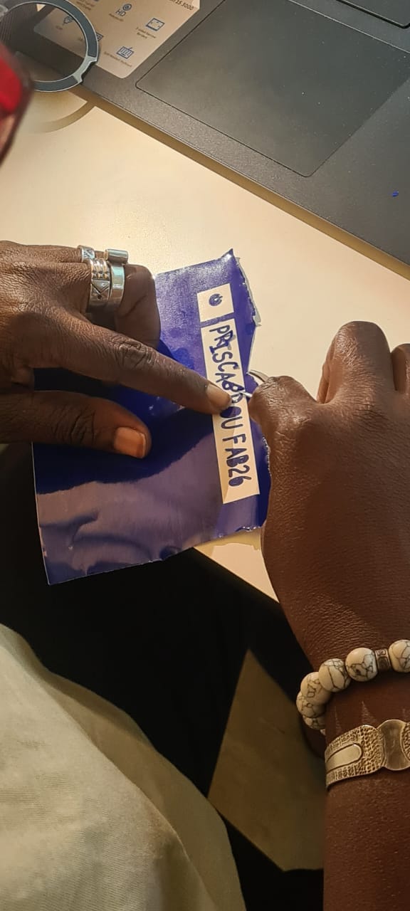 Decorative vinyl details applied to the acrylic panel surface.
05. Electronics Design
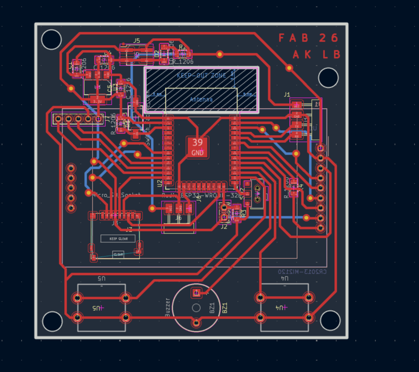
For the electronic design of the system, I used KiCad.
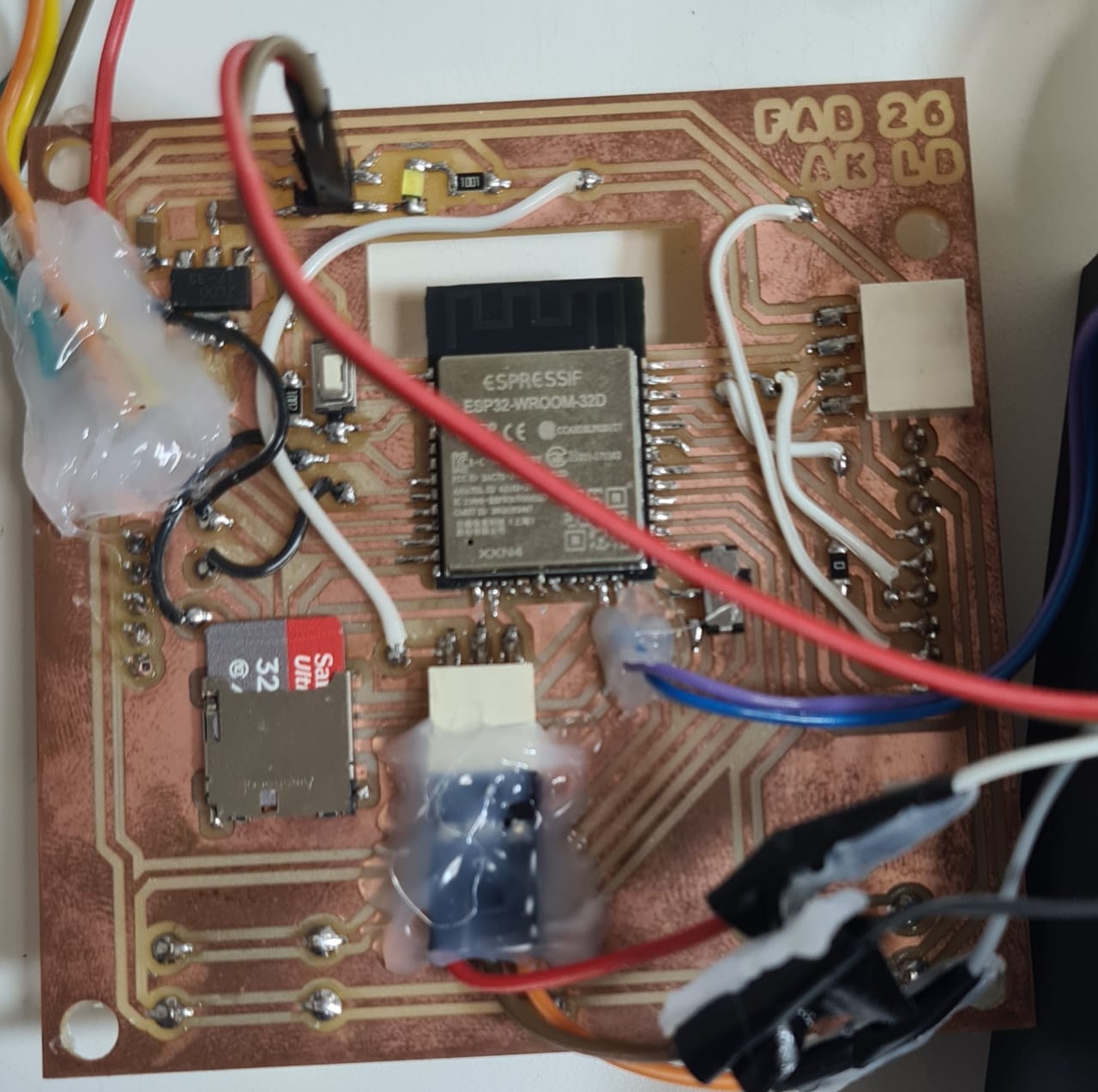
The circuit integrates the following components on a single custom PCB shaped as the map of Côte d'Ivoire:
- ESP32 microcontroller — the brain of the system
- TFT LCD screen — displays the real-time clock and date on the base
- RGB LEDs (NeoPixel) — each LED is geo-located on the map, representing a UNDP intervention city; their colors encode the status of the program
- Push buttons — allow the user to switch between display modes (clock, data visualization, animations)
- Buzzer — audio feedback for interactions
The schematics below are organized into three parts: power supply, main board, and the 3D render of the finished PCB.
Power Supply
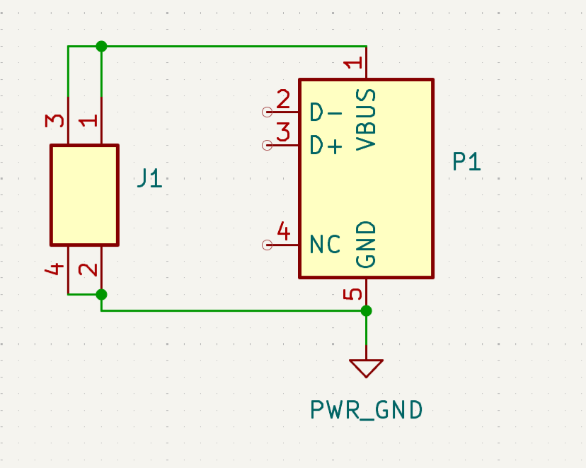 Power supply schematic: voltage regulation stage feeding the ESP32 and peripherals.
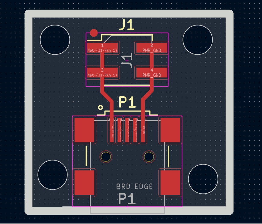 Power supply schematic: input connector and protection components.
Main Board
 Main board schematic: ESP32 microcontroller and its connections to the TFT screen.
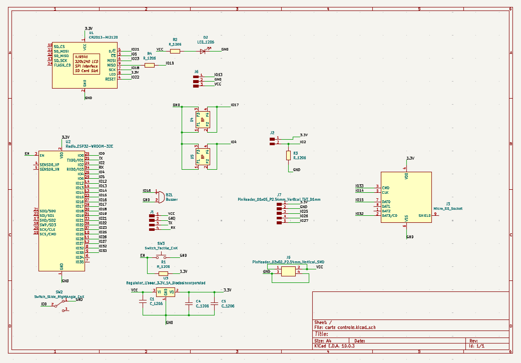 Main board schematic: RGB LED strip, push buttons, and buzzer wiring.
PCB 3D View
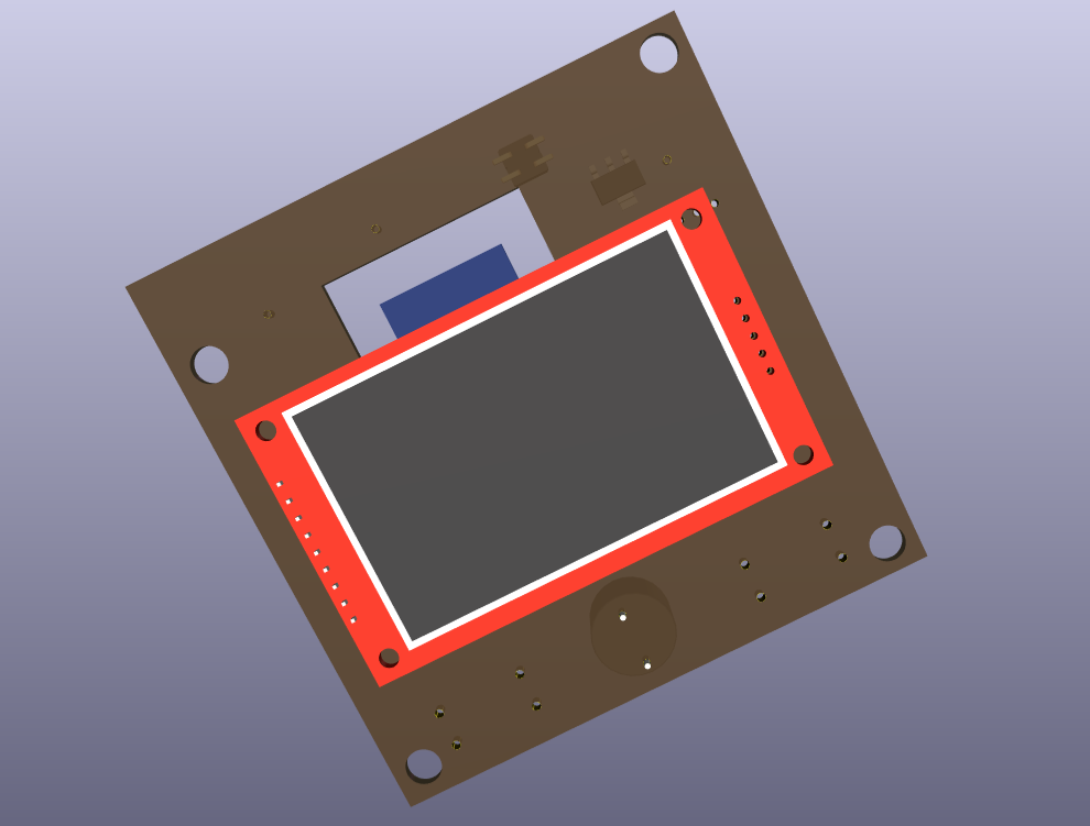 3D render of the PCB, top view, showing component placement across the map silhouette.
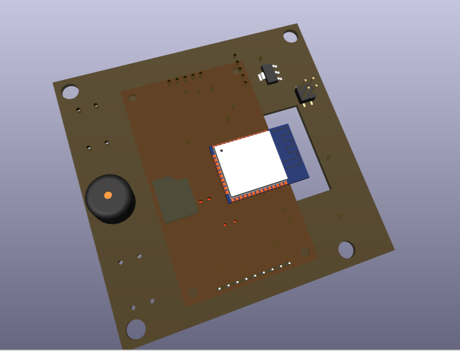 3D render of the PCB, angled view, showing the LED positions matching each district.
For more details on the electronics design process, refer to Week 6 — Electronics Design.
06. Electronics Production
The PCB was fabricated using the Roland SRM-20 milling machine in our FabLab.
PCB milling process on the Roland SRM-20, tracing the copper traces of the map-shaped board.
For the full milling and soldering procedure, refer to Week 8 — Electronics Production.
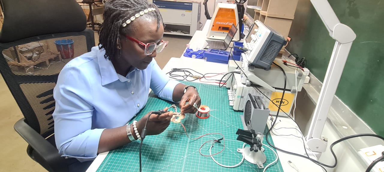 Hand-soldering the RGB LEDs and connectors onto the custom map-shaped PCB.
 PCB milling in progress on the Roland SRM-20.
 The milled PCB after machining, before component soldering.
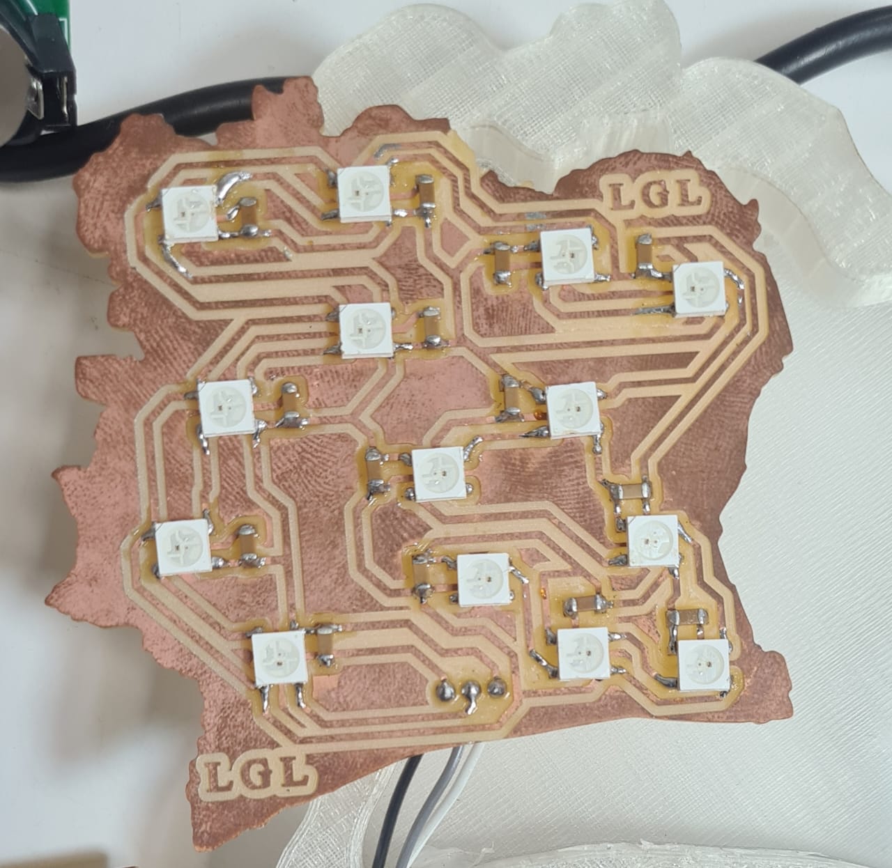 The fully soldered PCB, ready for integration into the enclosure.
07. Final Project — ESP32 Programming
This section documents the firmware running on the ESP32 that powers the interactive map. It manages the TFT display (clock view and district cards), the 14 RGB LEDs representing the districts of Côte d'Ivoire, the real-time clock (RTC), the two physical push buttons, the buzzer, and an embedded web server used to configure the time, alarms, and UNDP project status for each district — all without any internet connection, through a standalone Wi-Fi access point.
Technology stack:
| Component | Library | Role |
|---|---|---|
| Display | TFT_eSPI + LVGL (v8/v9) |
Graphical interface on the TFT screen |
| LEDs | Adafruit_NeoPixel |
Driving the 14 WS2812B RGB LEDs |
| Clock | RtcDS1302 |
Hardware real-time clock |
| Networking | ESPAsyncWebServer + ElegantOTA |
Remote configuration and wireless firmware updates |
| Storage | Preferences |
Non-volatile settings storage (flash) |
Architecture in one sentence
The device is a finite state machine: it idles on a clock screen, and temporarily switches to a district view, a full auto-review, or a random walkthrough — each state driving both the TFT screen and the LED strip in sync.
07.0 System Overview
The device operates as a button-driven finite state machine running entirely offline on the ESP32, with no dependency on internet connectivity for its core function.
How it works, in short:
-
Idle state — Clock mode. By default, the device displays the current time and date on the TFT screen, read from a local DS1302 hardware clock (RTC). All 14 LEDs stay off, and the screen also shows the status of the 3 configured alarms.
-
User interaction via two buttons. A short press cycles through individual districts or dismisses a ringing alarm. A long press (6 seconds) on either button triggers one of two automatic review modes — a full map overview or a randomized city-by-city tour.
-
District mode. When a specific district is selected, its corresponding LED lights up in a color that reflects the UNDP project status for that region (red = no project, blue = in progress, green = completed), while the TFT screen shows the district name and status label for 5 seconds before automatically returning to the clock.
-
Auto mode. All 14 LEDs light up simultaneously, each showing its district's current status, while the screen displays aggregate statistics — how many projects are completed, in progress, or non-existent across the country.
-
Walkthrough mode. The device cycles through all 14 districts one by one, in a shuffled order, spending 5 seconds on each — lighting the corresponding LED and displaying the district's name and UNDP status on screen, like a self-guided tour of the map.
-
Background tasks running continuously. In parallel, the firmware constantly checks for a triggered alarm (buzzing and showing an on-screen alert if one goes off), and keeps a lightweight web server active — allowing anyone connected to the device's own Wi-Fi access point to update the time, alarms, or a district's UNDP status through a browser, with all changes saved permanently to flash memory.
In essence: the clock is the resting state, the buttons are the only input, and the LEDs + TFT screen work together as a single synchronized display — whether showing the time, one region, or the whole country at a glance.
07.1 Hardware Configuration (Pins & Constants)
All physical wiring is centralized at the top of the sketch. This is the single place to edit if the wiring changes.
#define RTC_IO_PIN   26
#define RTC_SCLK_PIN 25
#define RTC_CE_PIN   27

#define LED_PIN      13
#define NUM_LEDS     14

#define PIN_BUTTON_1 17  // Green button
#define PIN_BUTTON_2 4   // Yellow button
#define PIN_BUZZER   16
The ESP32 also boots as a Wi-Fi Access Point, with its SSID and password defined here:
07.2 Data Structures: Districts & Project Status
The core business logic of the project relies on two elements:
ProjectStatus— a 3-state enum (INEXISTANT,EN_COURS,REALISE), each mapped to a color (red / blue / green).districts[]— an array of 14 entries mapping each district name to its physical LED index on the strip. This mapping guarantees that the correct LED lights up for the correct district.
const District districts[NUM_LEDS] = {
  {"Bas-Sassandra", 0, "Bas-Sassandra"},
  {"Montagnes", 1, "Montagnes"},
  // ...
};
Why this matters
Separating the district name from the LED index means the physical wiring can be reorganized without touching any other part of the code — only this table needs to be updated.
07.3 Data Persistence (Preferences / Flash Storage)
All configuration data must survive a reboot or power loss: the 3 alarms and the status of the 14 districts. The Preferences library (ESP32's equivalent of EEPROM) is used as a lightweight key-value store in flash memory.
loadSettings()— loads everything on bootsaveAlarm()/saveDistrictStatus()— persist a single modified value without rewriting everything else
This ensures that any change made through the web interface (alarm settings, district status) remains stored even after the device is powered off.
07.4 Embedded Web Interface (Remote Configuration)
The ESP32 serves its own HTML/CSS/JS page (stored in program memory via PROGMEM), accessible by connecting to the device's Wi-Fi access point. This interface allows the user to:
- Set the RTC date and time
- Configure 3 alarms (time + enable/disable)
- Update the UNDP status of each district (Non-existent / In Progress / Completed) through a dynamic table
The visual design reuses the colors of the Ivorian flag (orange / white / green) as top borders on cards, keeping the web UI visually consistent with the physical device.
Communication with the firmware goes through a small custom REST API (/api/status, /api/set_time, /api/set_alarm, /api/set_district), which replies in JSON.
07.5 REST API (Server Side)
Each web route is handled by a dedicated function:
| Route | Handler | Purpose |
|---|---|---|
/api/status |
handleStatus() |
Returns the current state (alarms + district statuses) as JSON |
/api/set_time |
handleSetTime() |
Updates the RTC date and time |
/api/set_alarm |
handleSetAlarm() |
Updates an alarm and persists it to flash |
/api/set_district |
handleSetDistrict() |
Updates a district's UNDP status and persists it to flash |
Each handler validates the presence of expected parameters before processing, and returns a JSON payload ({"success": true/false}) so the web UI can react accordingly.
07.6 LVGL Graphical Interface (TFT Screen)
initUI() builds three overlapping screens on a single root container (clock_screen), shown or hidden depending on the current system state:
- Clock screen — time, date, status of the 3 alarms, network info. This is the default idle screen.
- District card (
card_container) — district name, UNDP project status, colored status badge, and a progress bar counting down the 5-second display window before returning to the clock. - Auto mode screen (
auto_screen) — aggregate statistics (number of completed / in-progress / non-existent projects) during the automatic full-district review.
A tricolor bar (orange / white / green) at the top of the clock screen echoes the Ivorian flag, tying the on-screen UI to the physical map enclosure.
07.7 State Machine (Core Behavior)
The system behaves as a finite state machine with 4 possible states, managed centrally through changeState():
| State | Behavior | Duration |
|---|---|---|
STATE_CLOCK |
Default idle mode — clock displayed, LEDs off | — |
STATE_DISTRICT |
Displays a single district (its LED lights up in the color of its current status) | 5 s |
STATE_AUTO |
Lights up all LEDs at once and shows aggregate statistics | 6 s |
STATE_WALKTHROUGH |
Cycles through all districts one by one, in random order (Fisher–Yates shuffle) | 5 s per district |
Every state transition resets the internal timer (stateTimer) and updates the LED strip accordingly — this function is the bridge between the TFT display and the physical LED map.
07.8 Physical Button Handling
Two buttons provide four distinct interactions, differentiated by press duration:
| Button | Short press | Long press (6 s) |
|---|---|---|
| BP1 (green) | Next district / stops a ringing alarm | Enters Auto review mode |
| BP2 (yellow) | Shows / refreshes the current district | Enters Random walkthrough mode |
The code uses simple debouncing (delay(20) + state re-check) and distinguishes a short click from a long press by timing the press duration (pressTime) and tracking a isHeld flag.
07.9 Alarm System
checkAlarms() runs on every loop iteration and compares the current time against the 3 stored alarms. When a match is found:
- The buzzer blinks at 1 Hz (toggling every 500 ms)
- A red alert box appears on screen (
createAlarmAlertBox()) - The user can dismiss it via BP1 or the on-screen "OK" button
- A safety timeout automatically silences the alarm once the triggering minute has passed, preventing it from ringing indefinitely if left unattended
07.10 setup() and loop() — General Orchestration
setup() initializes, in order: I/O pins (buttons, buzzer), the LED strip, saved preferences, the RTC module (with fallback if the clock has lost time), the Wi-Fi access point, the web server and OTA endpoint, and finally the screen and LVGL interface.
loop() runs the following each cycle:
- Refresh the LVGL rendering (
lv_timer_handler) - Read the RTC time and update the clock display
- Check alarms
- Poll the buttons
- Handle automatic state transitions (return to the clock screen when a timer expires, advance the random walkthrough, etc.)
This non-blocking loop (no long delay() calls) allows the asynchronous web server to keep responding to requests while the display and LEDs continue to animate in parallel.
07.11 District → LED Index Mapping
| Index | District |
|---|---|
| 0 | Bas-Sassandra |
| 1 | Montagnes |
| 2 | Woroba |
| 3 | Sassandra-Marahoué |
| 4 | Denguélé |
| 5 | Savanes |
| 6 | Vallée du Bandama |
| 7 | Zanzan |
| 8 | Lacs |
| 9 | Yamoussoukro |
| 10 | Lagunes |
| 11 | Comoé |
| 12 | Abidjan |
| 13 | Gôh-Djiboua |
07.12 Libraries Used
| Library | Purpose |
|---|---|
WiFi.h |
Enables the ESP32's Wi-Fi Access Point mode, allowing devices to connect directly to the clock for configuration |
AsyncTCP.h |
Provides asynchronous TCP networking, required as a dependency for the async web server |
ESPAsyncWebServer.h |
Runs the embedded, non-blocking web server that serves the configuration interface and REST API |
ElegantOTA.h |
Adds an Over-The-Air (OTA) update page, allowing firmware to be updated wirelessly via the web interface |
Preferences.h |
Handles non-volatile storage (flash memory) for saving alarms and district statuses, so data survives a reboot |
Adafruit_NeoPixel.h |
Controls the 14 WS2812B RGB LEDs representing the districts on the physical map |
ThreeWire.h |
Implements the 3-wire communication protocol used to talk to the DS1302 RTC module |
RtcDS1302.h |
Drives the DS1302 real-time clock module, providing accurate date and time even when powered off |
lvgl.h |
Graphics library (LVGL) used to build and render the entire user interface on the TFT screen |
TFT_eSPI.h |
Low-level display driver that handles communication with the TFT LCD screen |
07.13 Pin Configuration
TFT Screen
Note
The TFT pin mapping (CS, DC, RST, CLK, MOSI) is not defined inside this .ino file — TFT_eSPI is configured through a separate User_Setup.h file at the library level, which isn't included in the sketch shown. Only the screen rotation is set here (SCREEN_ROTATION = 3, landscape rotated 180°).
RTC Module (DS1302)
| Signal | GPIO |
|---|---|
| CE/RST | 27 |
| DAT/IO | 26 |
| CLK/SCLK | 25 |
RGB LEDs
| Signal | GPIO |
|---|---|
| Data (DIN) | 13 |
Push Buttons
| Button | GPIO |
|---|---|
| Button 1 (green) | 17 |
| Button 2 (yellow) | 4 |
Buzzer
| Signal | GPIO |
|---|---|
| Buzzer | 16 |
07.14 Main Loop Logic
Loop:
├── Update LVGL rendering (lv_timer_handler)
├── Read current time from RTC (DS1302)
├── Check alarms (checkAlarms)
│   ├── If alarm triggers → buzzer blinks (1Hz) + alert box on TFT
│   └── Auto-dismiss after triggering minute passes
├── Poll button inputs (processButtons)
│   ├── BP1 short press → next district / stop alarm
│   ├── BP1 long press (6s) → enter Auto mode
│   ├── BP2 short press → show/refresh current district
│   └── BP2 long press (6s) → enter Walkthrough mode
└── State Machine (changeState):
    ├── STATE_CLOCK (default/idle):
    │   ├── Display time (HH:MM:SS) on TFT
    │   ├── Display date (Day DD Mon YYYY) on TFT
    │   ├── Display alarm status (A1/A2/A3 ON-OFF)
    │   └── LEDs → off
    ├── STATE_DISTRICT (5s):
    │   ├── Read stored UNDP status for selected district (flash)
    │   ├── Light up corresponding LED
    │   │   ├── Red    → No UNDP project
    │   │   ├── Blue   → Project in progress
    │   │   └── Green  → Project completed
    │   ├── TFT card → district name + status label
    │   └── TFT progress bar → 5s countdown before returning to clock
    ├── STATE_AUTO (6s):
    │   ├── Light up ALL 14 LEDs simultaneously (status colors)
    │   └── TFT screen → aggregate stats (completed / in progress / non-existent)
    └── STATE_WALKTHROUGH (5s per district):
        ├── Shuffle district order (Fisher–Yates)
        ├── Loop through each city sequentially
        ├── Light up corresponding LED (status color)
        └── TFT screen → district name + UNDP program status
07.15 Download the Code
The full C++ sketch is quite long, so it is provided as a download rather than inline: Download the firmware source (.zip)
08. Assembly & Final Testing
Once all modules were validated individually, I assembled the full system:
- Solder all components on the custom map-shaped PCB (LEDs, connectors)
- Insert the PCB into the translucent acrylic silhouette of Côte d'Ivoire
- Mount the silhouette panel on top of the 3D-printed black base
- Install the TFT screen, push buttons, and ESP32 inside the base enclosure
- Final wiring and cable management between base and panel
- Power-on test — verify the clock display and the LED geo-visualization
- Validate all 3 interactive modes and button switching
- Final demo — showcase UNDP regional data visualized across the map
 Inserting the completed PCB into the translucent acrylic silhouette of Côte d'Ivoire.
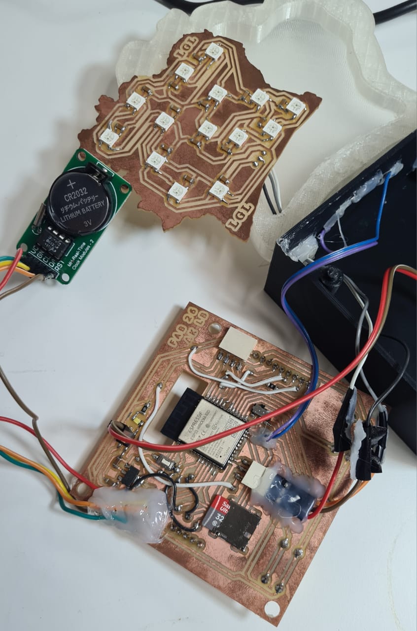 Cable management between the base and the map panel during final wiring.
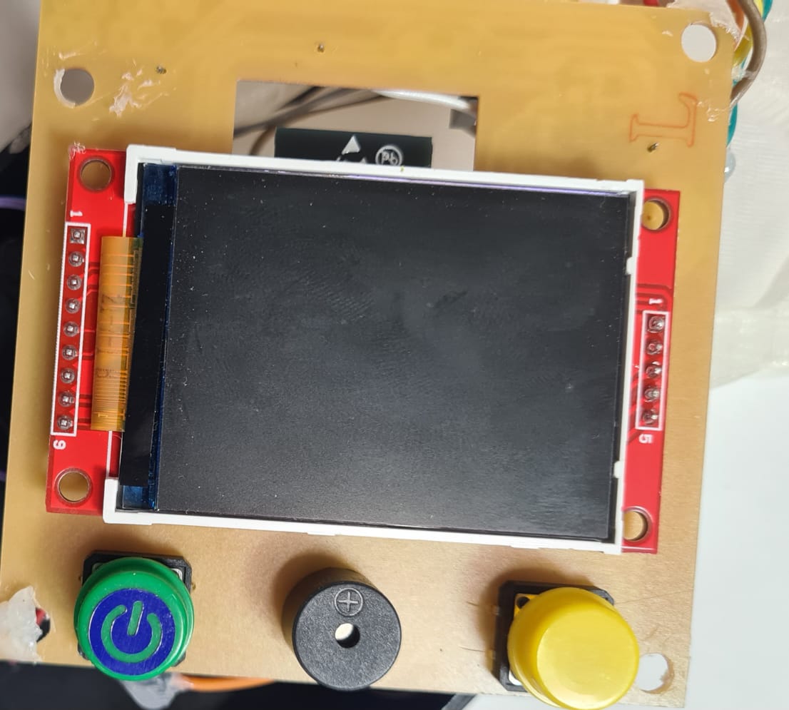 Power-on test, verifying the TFT clock display and LED activation.
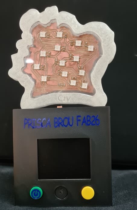 Front view of the assembled device in Clock mode.
 Assembled device in District mode, showing an active LED and the corresponding status card on screen.
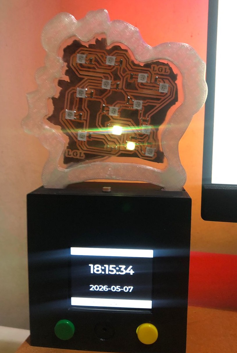 Close-up of the map panel with multiple district LEDs lit, showing the UNDP status color coding.
08.1 Project Dashboard
Demo of the web-based dashboard, used to configure the clock, alarms, and district status from a browser.
08.2 Alarm
Demo of the alarm feature, showing the on-screen alert and buzzer feedback when an alarm triggers.
09. Files
| File | Description |
|---|---|
| 📐 Project Files (2D / DXF) | 2D / DXF model of the final project |
| 📦 Enclosure Files (3D) | Complete 3D model of the enclosure |
| ⚙️ Electronics & Programming Files | Full electronics and programming documentation, including personal notes and advice |