Electronics production
Group assignment:
-
Characterize the design rules for your in-house PCB production process: document feeds, speeds, plunge rate, depth of cut (traces and outline) and tooling.
-
extra credit: send a PCB out to a board house
-
Document your work to the group work page and reflect on your individual page what you learned
The Machine: Roland SRM-20
The Roland SRM-20 is a compact, highly precise desktop mill. Within the Fab Academy ecosystem, it is perfect for rapidly prototyping circuit boards by mechanically removing the copper layer from a FR1 substrate (phenolic paper resin) without involving any hazardous chemicals.
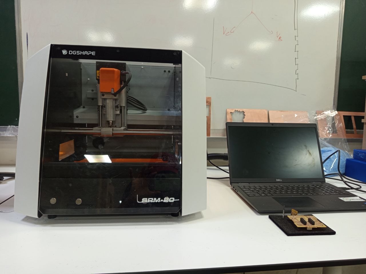
The SRM-20 compact milling machine combines compact size, power, and affordability. It makes it easy to produce realistic parts and prototypes and fits seamlessly into any environment—whether an office, home, or classroom. Portable, this milling machine can machine a wide variety of materials, including modeling clay, synthetic wood, foam, acrylic, polyacetate, ABS, and printed circuit boards.
Preparing the Line Test File
To determine the minimum track width that the machine can successfully isolate without lifting the copper, we utilize the standard Line Test file. This pattern features trace widths and gaps that gradually narrow from 0.040 inches down to 0.001 inches.
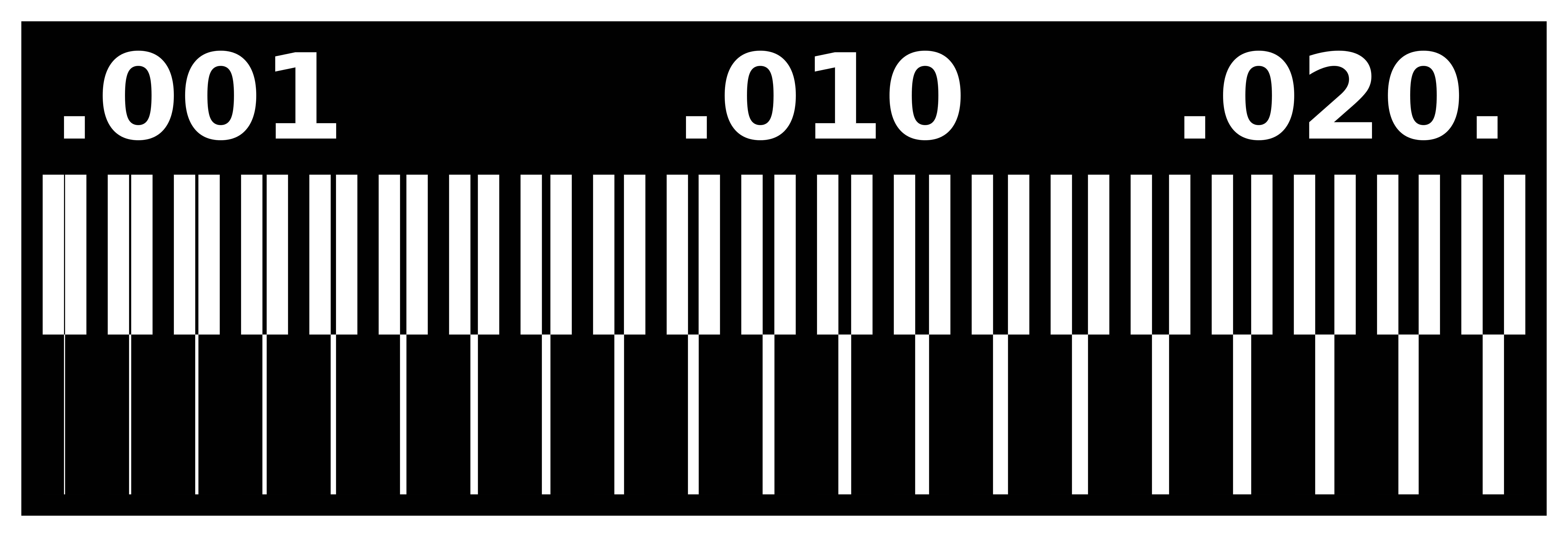

Source :(https://fabacademy.org/2024/labs/inphb/assignments/week04/)
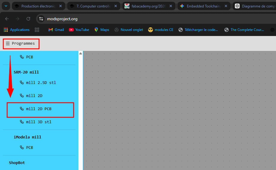
We used the online tool Mods CE (modsprojects.org) to calculate the toolpaths (G-code) following this workflow:
- Program Selection:
Navigate toPrograms > SRM-20 mill 2D PCB.
- Loading Traces:
Import the high-resolution.pngfile representing the board's internal circuit traces.
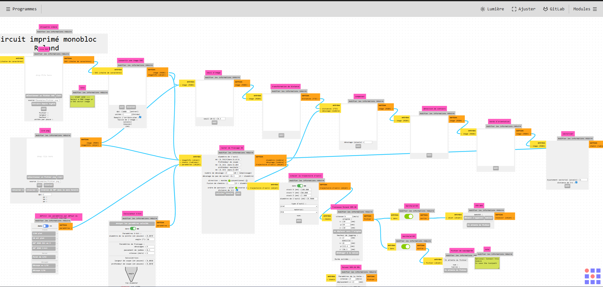
- Calculating Traces (1/64" Bit):
Select themill traces (1/64)preset block, which automatically configures the default depth and height values for copper isolation.
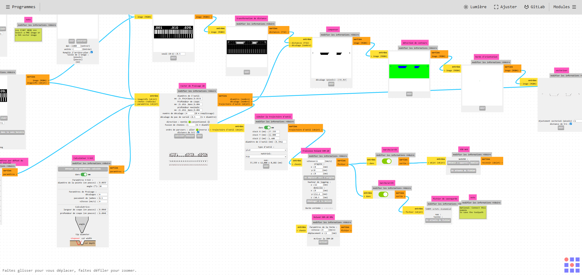
- Calculating the Outline (1/32" Bit):
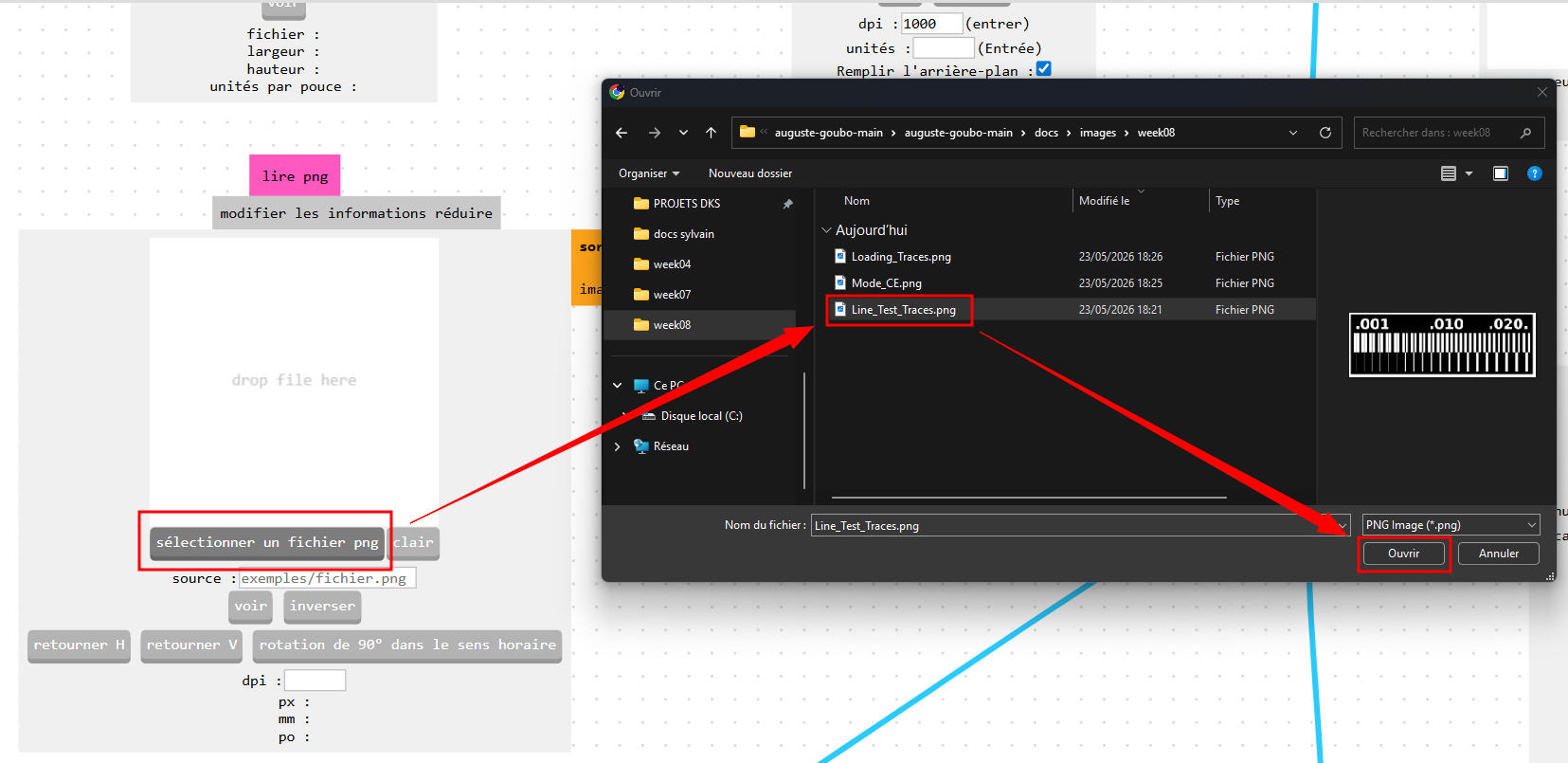
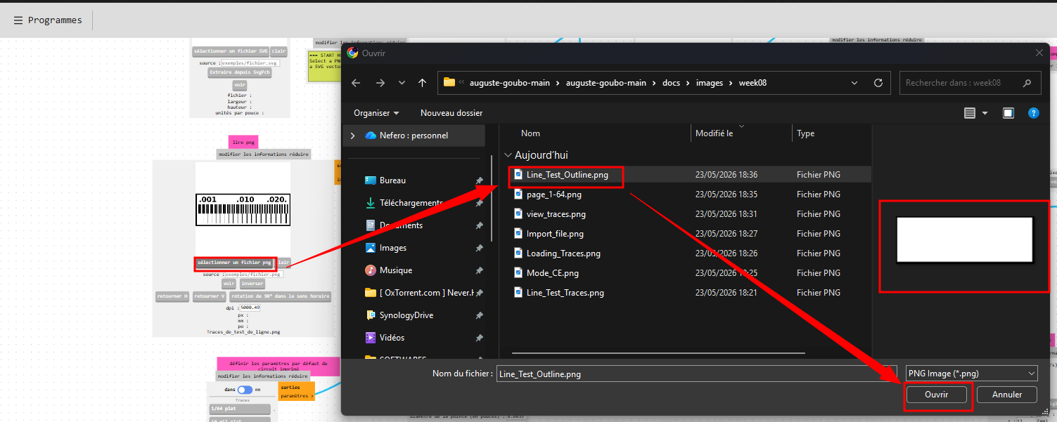
Load the secondary.pngfile meant for cutting the outer boundary of the board. ClickInvert(ensuring the machine mills away the outside area) and select themill outline (1/32)preset block.
-
Setting Origins:
In the Roland SRM-20 control module, define the absolute reference coordinates \((X0, Y0, Z0)\) and configure a safe Jog height of 12 mm. -
Saving the File:
Attach a file saving module (Modules > Open Server module > File / Save) to automatically download the finalized.rmltoolpath file.


Characterized Cutting Parameters (Feeds & Speeds)
Based on our calibration runs, we established the following optimized parameters for our PCB manufacturing workflow:
| Operation | Tooling (End Mill) | Cut Depth | Feed Rate | Plunge Rate |
|---|---|---|---|---|
| Engraving Traces | 2-flute 1/64" (~0.4 mm) | 0.1 mm | 4 mm/s | 2 mm/s |
| Cutting Outline | 2-flute 1/32" (~0.8 mm) | 0.6 mm (via multiple passes) | 4 mm/s | 2 mm/s |
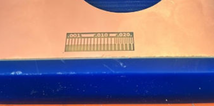
Line Test Results Analysis
A close inspection of our milled test board yielded critical design limitations that we must respect during the upcoming Electronics Design weeks:
-
Isolation Limit: The machine safely isolates clean, uniform copper traces down to a width of
0.010 to 0.015 inches (0.25 mm to 0.38 mm). Below this range, mechanical vibrations or inadequate substrate adhesion can easily tear the delicate copper off the FR1 board. -
Minimum Clearance: The physical gap separating two distinct electrical traces must be strictly wider than the diameter of our engraving bit (1/64" or ~0.4 mm). If the spacing is any smaller, the tool physically cannot pass between them, leaving a thin bridge of copper that will cause a short circuit.