Mechanical design, machine design
Group assignment:
- Design a machine that includes mechanism + actuation + automation + application
- Build the mechanical parts and operate it manually
- Actuate and automate your machine
- Document the group project and your individual contribution
Project Overview: 5-Bar Linkage SCARA Drawing Robot
For this assignment, our team designed, fabricated, assembled, and tested a 2-Degree-of-Freedom (2-DOF) Planar 5-Bar Parallel SCARA Drawing Robot (Pen Plotter).
Parallel SCARA mechanisms are widely celebrated in robotics for planar manipulation because both heavy actuators remain stationary on the fixed chassis base. This configuration drastically lowers the inertia of moving links, prevents cable dragging across moving joints, and provides high structural rigidity compared to serial open-chain robot arms.
The machine was conceived and evaluated through the four foundational pillars required by the Fab Academy:
- Mechanism: A symmetric planar five-bar closed-loop kinematic chain composed of a ground base link, two driving proximal arms, two driven distal forearms, and a central end-effector tool carriage holding a pen.
- Actuation: Explored and compared two actuator strategies:
- Dual Micro-Servos (SG90) for lightweight, direct angular position control.
- Dual NEMA 17 Stepper Motors with microstepping drivers for high-torque, precise path tracking and stiffness.
- Automation: Microcontroller integration (ESP32 / Arduino) running forward and inverse kinematics algorithms to translate Cartesian (X, Y) coordinate paths into coordinated motor trajectories.
- Application: Automated 2D pen plotting, reproducing geometric patterns, curves, and drawings on paper using an integrated ballpoint pen mechanism.
Materials and Equipment
| Category | Component / Tool | Specifications / Purpose |
|---|---|---|
| Digital Fabrication | Original Prusa MK4S 3D Printer | 0.4 mm nozzle, heated PEI bed, direct drive extruder |
| Material | PLA Filament (1.75 mm) | Blue PLA, Orange PLA, Silver/Grey PLA |
| CAD Software | Dassault Systèmes SolidWorks | Parametric 3D part modeling and kinematics assembly |
| Actuators (Option A) | 2x SG90 Micro Servo Motors | Operating voltage 4.8V - 6V, 1.8 kg·cm torque |
| Actuators (Option B) | 2x NEMA 17 Stepper Motors | 1.8° step angle (200 steps/rev), 42×42 mm, high holding torque |
| Controller | ESP32 Dev Board / Arduino | Kinematics computation and motor signal generation |
| End-Effector Tool | Ballpoint pen (Bic Cristal) | Writing / drawing instrument |
| Fasteners & Hardware | M3 & M4 screws, locknuts, washers | Revolute joint pivots and structural fastening |
| Assembly Tools | 20W Hot Melt Glue Gun, screwdrivers, cutters | Structural reinforcement, wire securing, post-processing |
Mechanical Design and 3D Modeling (CAD)
The mechanical system was designed from scratch in SolidWorks with parametric constraints. The core objective was to achieve a balanced planar workspace with minimal singular configurations within the intended drawing area.
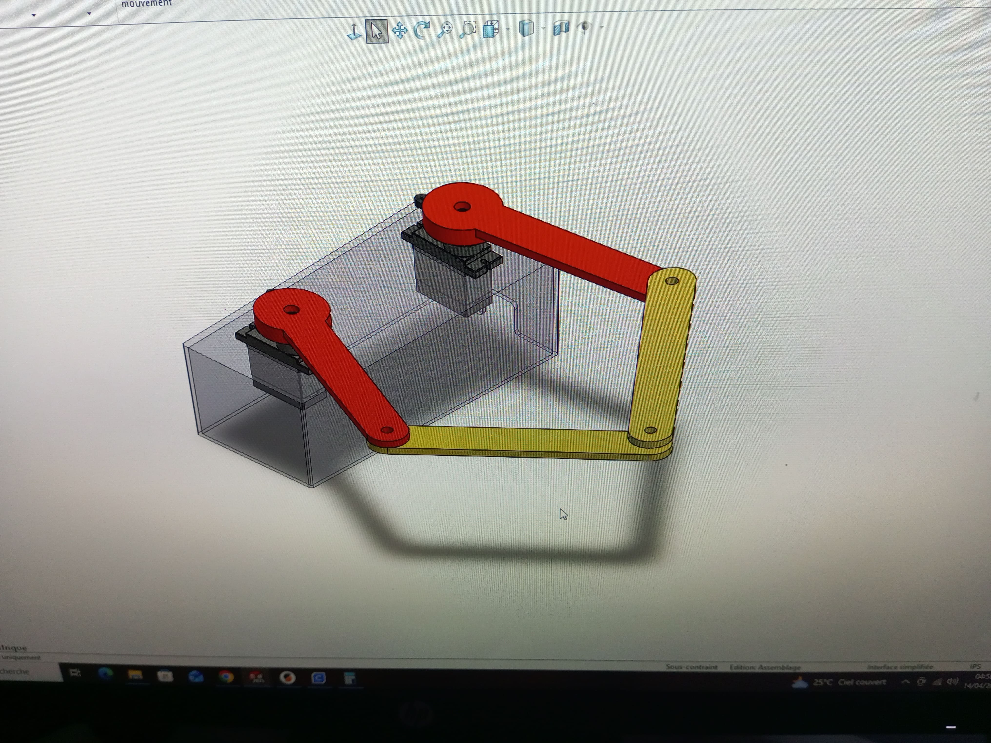
Design Components
- Chassis & Base Housing: An enclosed rectangular housing designed with precision mounting pockets to firmly position the two base actuators at a fixed distance d = 80 mm apart. It provides stability, internal routing space for wiring, and an elevated stance for the arms to swing freely over the paper.
- Proximal Arms (Shoulder Links): Two primary rotating links (L1 = 90 mm) keyed to press-fit and screw directly onto the motor output shafts / servo horns.
- Distal Forearms: Two secondary connecting links (L2 = 120 mm) featuring precision reamed pivot bushings on both ends to form low-friction revolute joints.
- End-Effector Pen Holder: A specialized vertical clamping sleeve designed to hold a standard Bic ballpoint pen securely perpendicular to the drawing surface while allowing slight vertical compliance to accommodate minor paper surface variations.
Digital Fabrication: 3D Printing
All mechanical parts were 3D printed in the lab on our Original Prusa MK4S 3D printer.
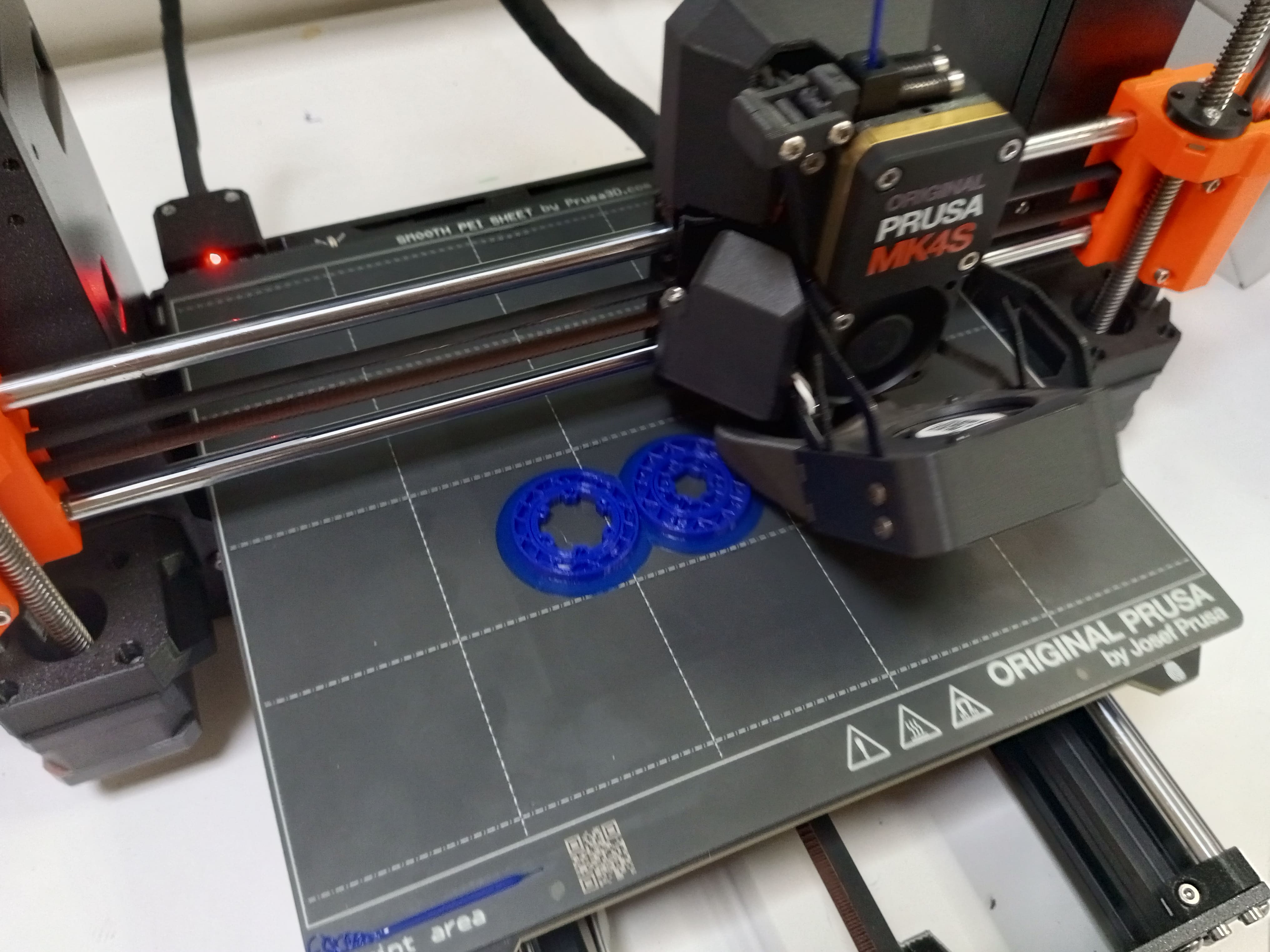
Slicing and Printing Parameters
- Printer: Original Prusa MK4S
- Material: PLA (Blue for proximal arms, Orange for base box, Silver/Grey for forearms)
- Layer Height: 0.20 mm (Quality profile)
- Infill Density: 25% Gyroid infill for isotropic rigidity
- Wall Perimeters: 3 solid perimeters to maximize strength around the pivot screw holes and motor shaft hubs
- Print Speed: 60 - 150 mm/s
- Bed Temperature: 60°C
- Nozzle Temperature: 210°C
- Supports: None (all parts were designed with flat orientations to avoid overhangs)
After printing, the parts were cleaned of any brim and checked for dimensional accuracy. Pivot holes were inspected to ensure smooth fitment with M3 pivot bolts.
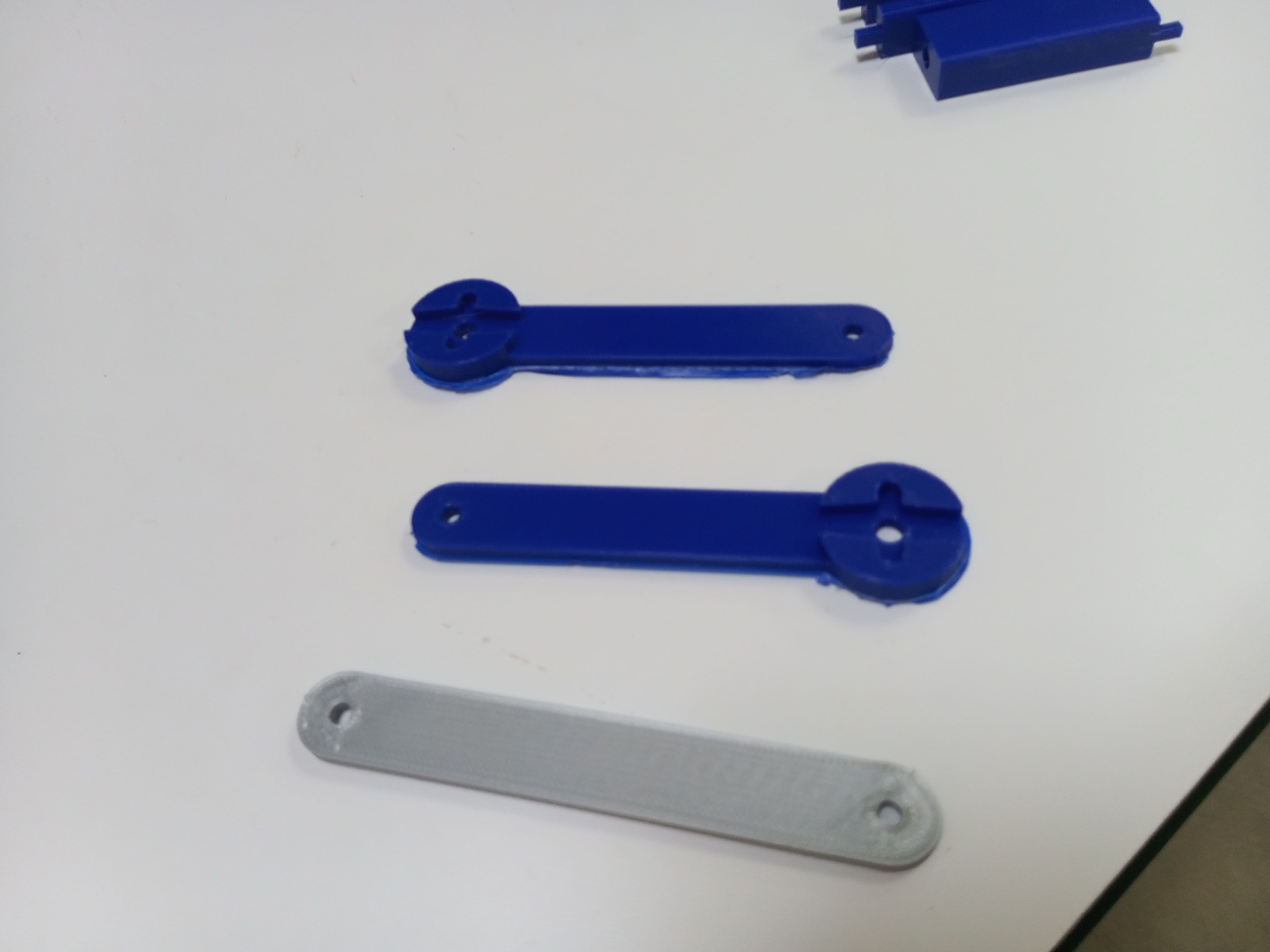
Mechanical Assembly
Once fabrication was completed, the physical assembly was carried out in stages:
- Actuator Installation: The actuators were seated inside their designated base pockets.
- Proximal Arm Coupling: The two blue shoulder links were secured to the actuator horns.
- Joint Linkage Assembly: The distal forearm links were coupled to the proximal arms using M3 shoulder screws, nylon locknuts, and smooth washers to create low-friction revolute joints without radial play.
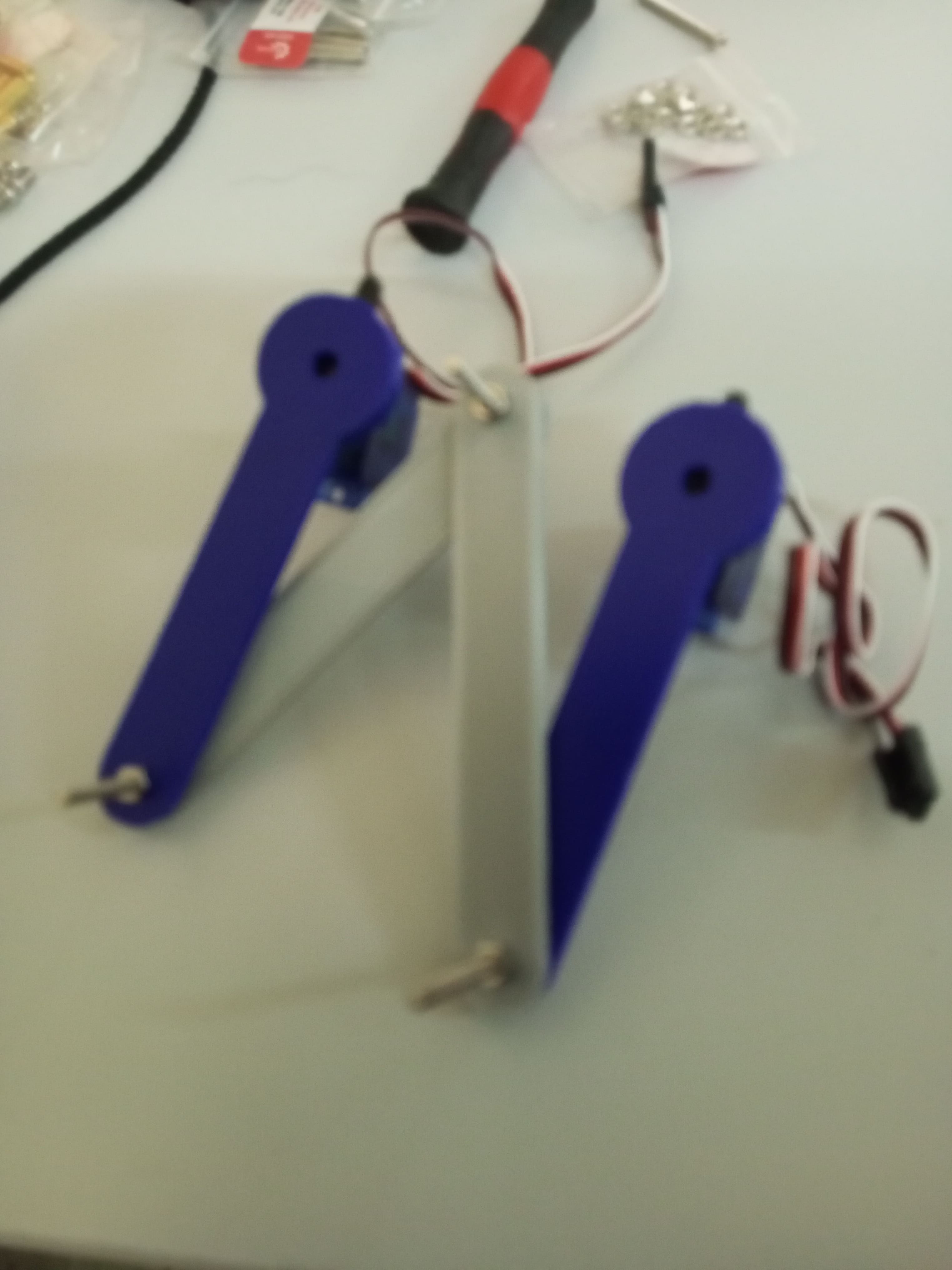
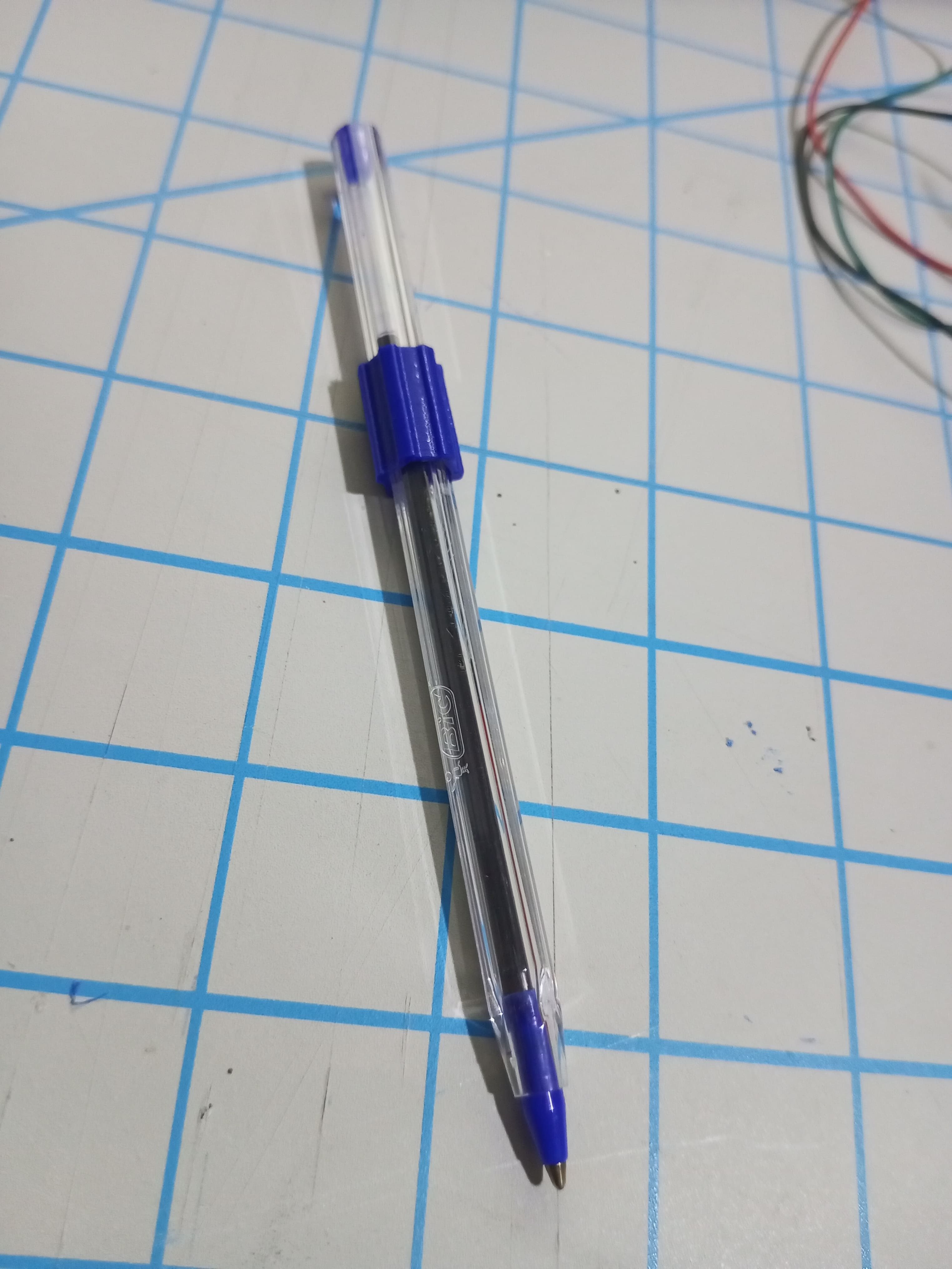
- Pen Clamping System: The 3D printed pen sleeve was installed at the intersection of the two distal links, and the Bic ballpoint pen was inserted and locked in place.
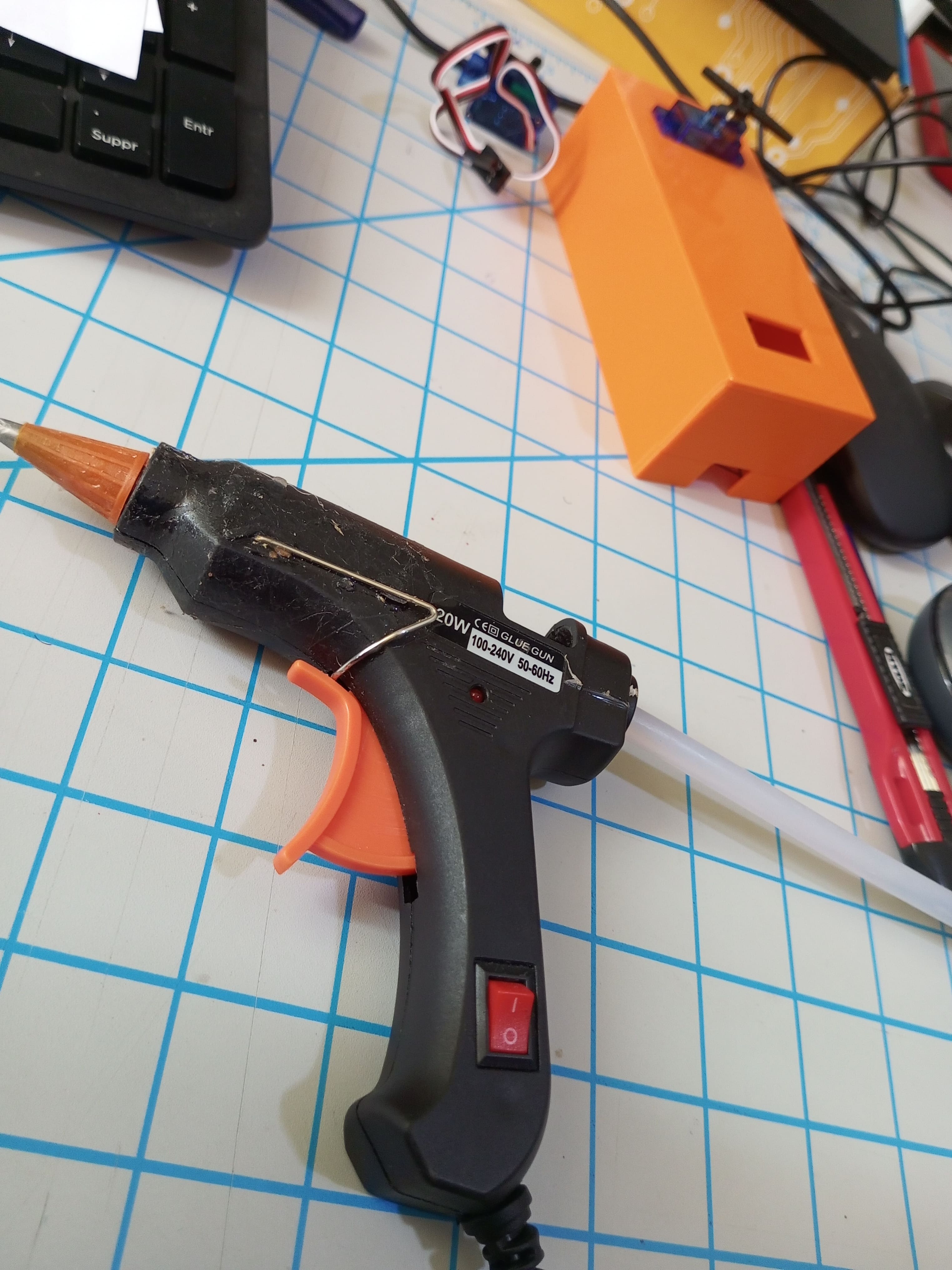
- Structural Bracing & Glue Gun Reinforcement: A 20W hot-melt glue gun was used inside the chassis to immobilize the micro-servo bodies securely against their mounting walls and anchor the wiring, preventing any mechanical flexing during operation.
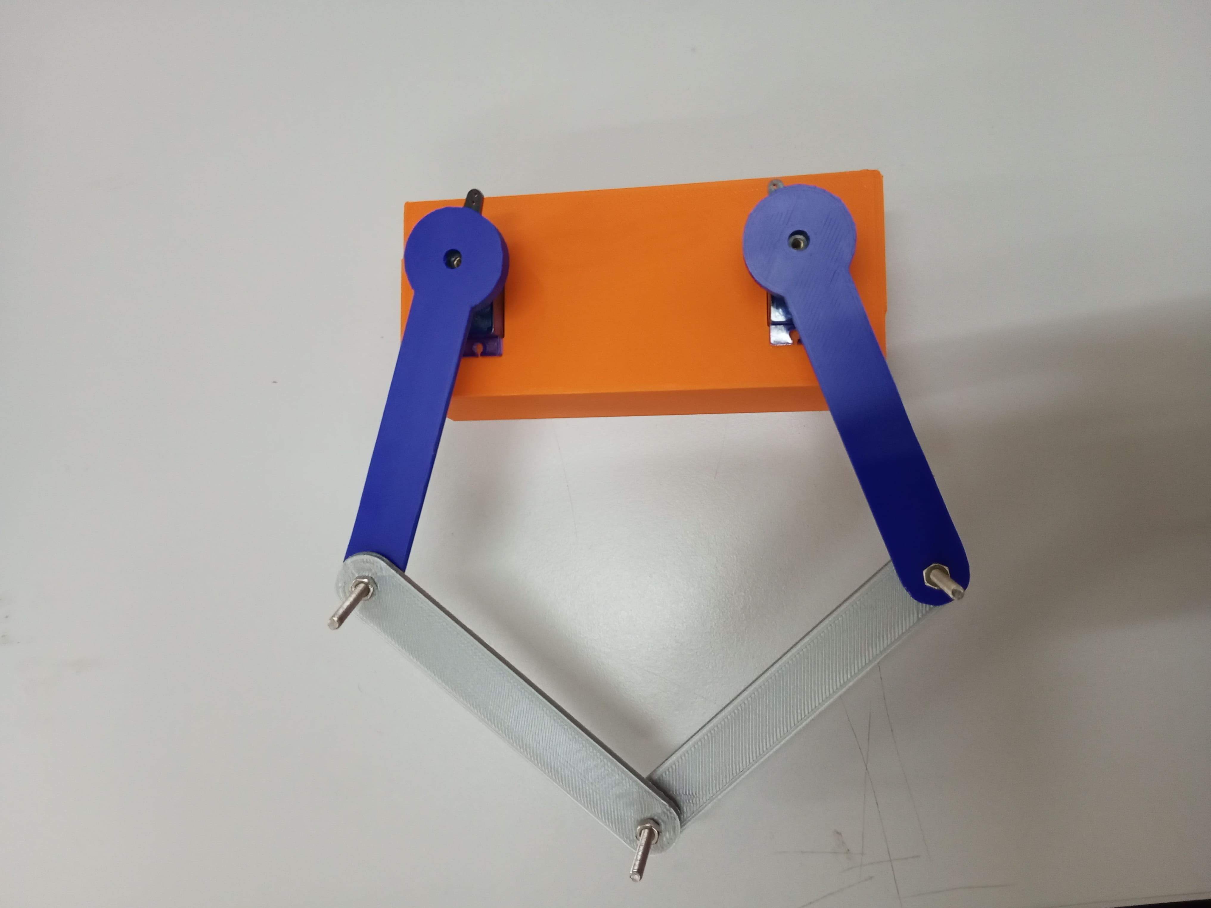
- Final Assembled SCARA Mechanism: The completed 5-bar linkage was placed over the drawing paper.
Manual Mechanical Operation (Fab Academy Requirement)
A critical milestone in the Mechanical Design week is to operate the mechanical parts manually prior to full automation. This validates:
- Smoothness of all 4 rotational pivot joints.
- Total range of motion across the intended drawing envelope.
- Absence of mechanical interference, joint collisions, or binding between overlapping links.
- Structural rigidity of the links under manual manipulation.
Manual Operation Tests
Video above: Manual manipulation testing showing the smooth kinematic travel and range of motion of the 5-bar linkage.
Video above: Validating end-effector planar motion and joint compliance manually over the drawing plane.
Actuation and Kinematics Modeling
1. Mathematical Kinematics (5-Bar Parallel Mechanism)
The planar 5-bar linkage consists of two base joints J1 and J2 separated by a distance d along the horizontal axis:
- Left actuator pivot: J1 = (-d/2, 0)
- Right actuator pivot: J2 = (+d/2, 0)
- Proximal links: length L1 at angles θ1 and θ2
- Distal links: length L2 meeting at the pen tip P = (X, Y)
         P (X, Y) [Pen Tip]
         / \
        /   \  L2 (Distal links)
       /     \
   Elbow1   Elbow2
     |         |
     | L1      | L1 (Proximal links)
    J1---------J2  (Base distance d)
   Left       Right
   Motor      Motor
Inverse Kinematics Formulation
To determine the required motor angles θ1 and θ2 for a given target coordinate (X, Y):
Left kinematic chain:
  R1² = (X + d/2)² + Y²
  β1  = atan2(Y, X + d/2)
  cos(α1) = (L1² + R1² - L2²) / (2 · L1 · R1)
  θ1  = β1 + α1

Right kinematic chain:
  R2² = (X - d/2)² + Y²
  β2  = atan2(Y, X - d/2)
  cos(α2) = (L1² + R2² - L2²) / (2 · L1 · R2)
  θ2  = β2 - α2
Where: - R1 and R2 are the straight-line distances from each base motor pivot to the pen tip. - α1 and α2 are the interior triangle angles computed via the law of cosines. - β1 and β2 are the base polar angles toward the target point.
2. Exploring Actuator Alternatives: Servos vs. Steppers
Our team built and evaluated two distinct actuation architectures:
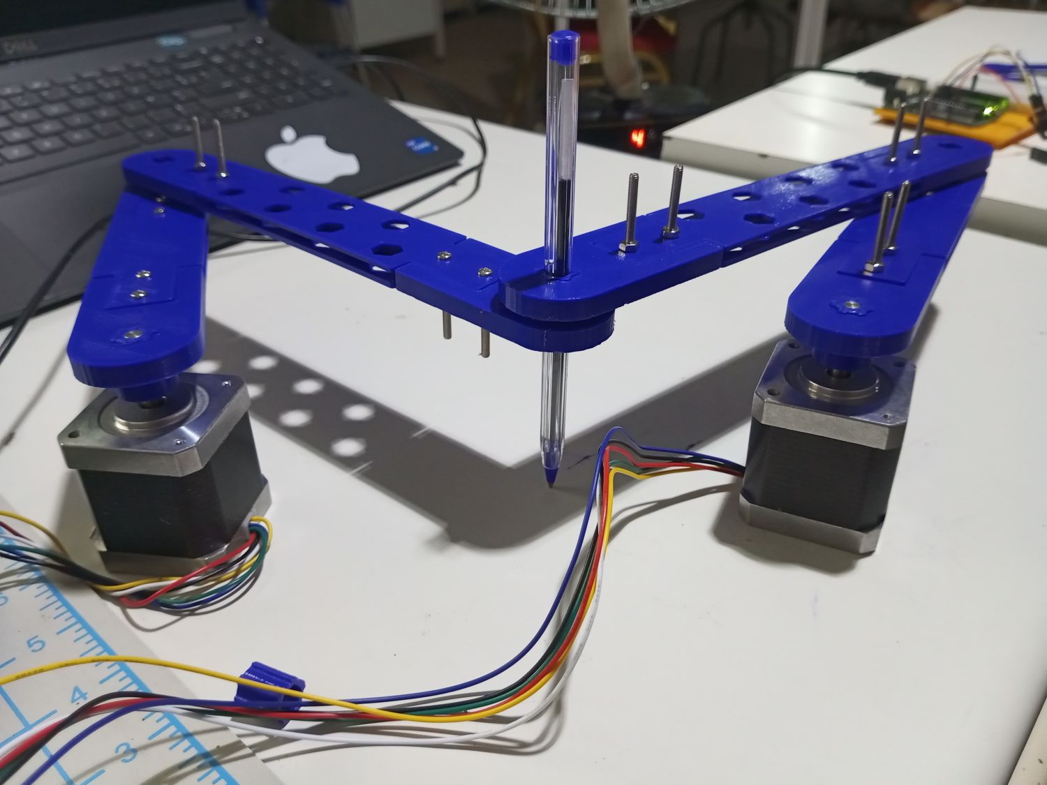
Prototype B: High-rigidity 5-bar linkage mechanism actuated directly by two NEMA 17 stepper motors.
| Feature | Prototype A (Dual SG90 Servos) | Prototype B (Dual NEMA 17 Steppers) |
|---|---|---|
| Form Factor | Extremely compact, lightweight | Heavier, rigid benchtop machine |
| Control Interface | Standard PWM pulse (50 Hz) | STEP / DIR pulses via A4988 / CNC Shield |
| Positioning | Absolute feedback inside servo | Incremental microstepping (up to 1/16 or 1/32) |
| Torque & Rigidity | Moderate (~1.8 kg·cm), slight internal gear play | Very high (~4.5 kg·cm), zero backlash |
| Best Application | Fast proof-of-concept and mobile educational plotter | Precision continuous line drawing and repeatable CNC plotting |
Firmware and Automation Code
An Arduino / ESP32 firmware was created to implement the inverse kinematics and drive the robot arms smoothly along predefined trajectories (lines, circles, and sweeps).
/*
  5-Bar Linkage Planar SCARA Robot Controller
  Fab Lab INP-HB - Fab Academy 2026 - Week 12
  Dual Servo Actuation with Geometric Inverse Kinematics
*/

#include <ESP32Servo.h>
#include <math.h>

Servo servoLeft;
Servo servoRight;

const int SERVO_LEFT_PIN  = 18;
const int SERVO_RIGHT_PIN = 19;

// Geometric parameters (in mm)
const float D  = 80.0;   // Distance between actuator axes
const float L1 = 90.0;   // Length of proximal arms
const float L2 = 120.0;  // Length of distal arms

// Inverse Kinematics calculation
bool computeIK(float x, float y, float &theta1_deg, float &theta2_deg) {
  float x1 = x + D / 2.0;
  float r1_sq = x1 * x1 + y * y;
  float r1 = sqrt(r1_sq);

  float x2 = x - D / 2.0;
  float r2_sq = x2 * x2 + y * y;
  float r2 = sqrt(r2_sq);

  // Workspace boundary check
  if (r1 > (L1 + L2) || r1 < fabs(L1 - L2) ||
      r2 > (L1 + L2) || r2 < fabs(L1 - L2)) {
    return false;
  }

  float cos_alpha1 = (L1 * L1 + r1_sq - L2 * L2) / (2.0 * L1 * r1);
  float cos_alpha2 = (L1 * L1 + r2_sq - L2 * L2) / (2.0 * L1 * r2);
  if (cos_alpha1 < -1.0 || cos_alpha1 > 1.0 || cos_alpha2 < -1.0 || cos_alpha2 > 1.0) {
    return false;
  }

  float theta1 = atan2(y, x1) + acos(cos_alpha1);
  float theta2 = atan2(y, x2) - acos(cos_alpha2);

  theta1_deg = theta1 * 180.0 / M_PI;
  theta2_deg = theta2 * 180.0 / M_PI;
  return true;
}

void moveToXY(float x, float y, int delayMs = 25) {
  float th1, th2;
  if (computeIK(x, y, th1, th2)) {
    servoLeft.write(constrain((int)th1, 0, 180));
    servoRight.write(constrain((int)th2, 0, 180));
    delay(delayMs);
  }
}

void setup() {
  Serial.begin(115200);
  ESP32PWM::allocateTimer(0);
  ESP32PWM::allocateTimer(1);
  servoLeft.setPeriodHertz(50);
  servoRight.setPeriodHertz(50);
  servoLeft.attach(SERVO_LEFT_PIN, 500, 2500);
  servoRight.attach(SERVO_RIGHT_PIN, 500, 2500);

  // Position at home coordinates
  moveToXY(0, 130, 1000);
}

void loop() {
  // Demonstration: draw a continuous circle in the workspace
  float cx = 0, cy = 130, radius = 25;
  for (float angle = 0; angle <= 360; angle += 5) {
    float rad = angle * M_PI / 180.0;
    moveToXY(cx + radius * cos(rad), cy + radius * sin(rad), 30);
  }
  delay(1000);
}
Results, Observations and Troubleshooting
What Worked
- Clean 3D Prints: The Prusa MK4S produced accurate parts with good layer adhesion and clean hole dimensions.
- Smooth Manual Operation: The 5-bar linkage operated without mechanical binding or stiff spots across the target workspace.
- Dual Actuation Exploration: Comparing the compact servo version with the NEMA 17 stepper version gave the team clear practical insight into precision versus portability trade-offs.
Challenges Encountered and Solutions
- Pivot Joint Friction vs Play: If the M3 bolts were too tight, the joints had too much friction for the small servos; if too loose, the pen wobbled. We resolved this by using smooth nylon-insert locknuts and washers, adjusting each pivot to rotate smoothly with zero axial wobble.
- Servo Mount Flex: The lightweight plastic servo ears exhibited slight flex under load. We reinforced the mounts inside the housing using hot-melt adhesive to eliminate flex.
- Pen Pressure: Ensuring constant pen tip contact on paper without jamming required adjusting the vertical pen height and testing on a flat cutting mat surface.
Individual Contributions
In accordance with Fab Academy criteria, the individual contributions are detailed below:
| Team Member | Individual Contribution | Student Documentation Page |
|---|---|---|
| Prisca Brou | • Parametric 3D CAD modeling of the 5-bar linkage, base enclosure, and pen clamp in SolidWorks. • Slicing and 3D printing of all mechanical components on the Original Prusa MK4S. • Mechanical assembly of the servo-based SCARA robot, pivot joint tuning, and hot glue reinforcement. • Manual actuation testing, video recordings, and individual reflection. |
Prisca's Week 12 Page |
| Auguste Dimitri Goubo | • Prototyping and mechanical design of the high-torque NEMA 17 stepper-driven parallel plotter mechanism. • Kinematic analysis, manual mechanical verification, and joint mobility testing. • Actuator wiring, driver configuration, and automation testing for precision trajectory drawing. • Group assignment documentation and synthesis. |
Auguste's Week 12 Page |