7. Computer controlled machining
Group assignment:
-
Complete your lab's safety training
-
Test runout, alignment, fixturing, speeds, feeds, materials and toolpaths for your machine
-
Document your work to the group work page and reflect on your individual page what you learned
To see our group assignment click here
Individual assignment:
-
Make (design+mill+assemble) something big(~meter-scale)
-
extra credit: don't use fasteners or glue
-
extra credit: include curved surfaces.
-
extra credit: use three-axis toolpaths
Introduction to the project
As part of this session on computer-controlled machining, we undertook the design and construction of an optimized corner storage unit, as shown in the file
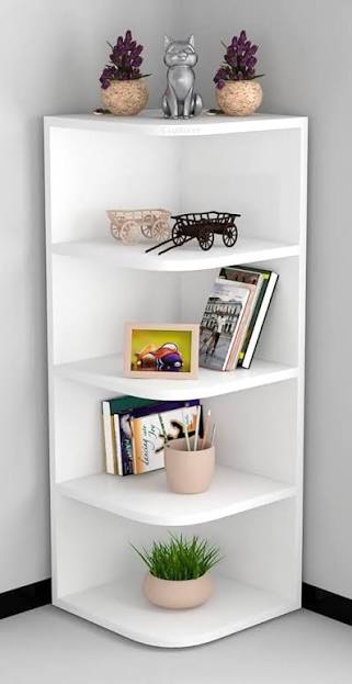
This project aims to leverage the precision and work surface of the ShopBot Alpha 96 to transform large-format wood panels into a functional, aesthetic, and self-supporting structure, incorporating rounded shelves and a robust assembly system.
Project Specifications
The goal is to build a corner cabinet with precise dimensions, optimized for machining on the ShopBot Alpha 96. Based on the visual model, we have defined the following dimensional parameters:
-
Overall Dimensions: Our cabinet has a total height of 1000 mm and a width of 370 mm.
-
Structure and Levels: The design incorporates 5 storage levels, thereby making optimal use of vertical space.
-
Spacing: A consistent 200 mm gap is maintained between each shelf to ensure visual harmony and uniform functionality.
-
Shelf Geometry:
-
Each shelf consists of a square panel measuring 370 mm x 370 mm.
-
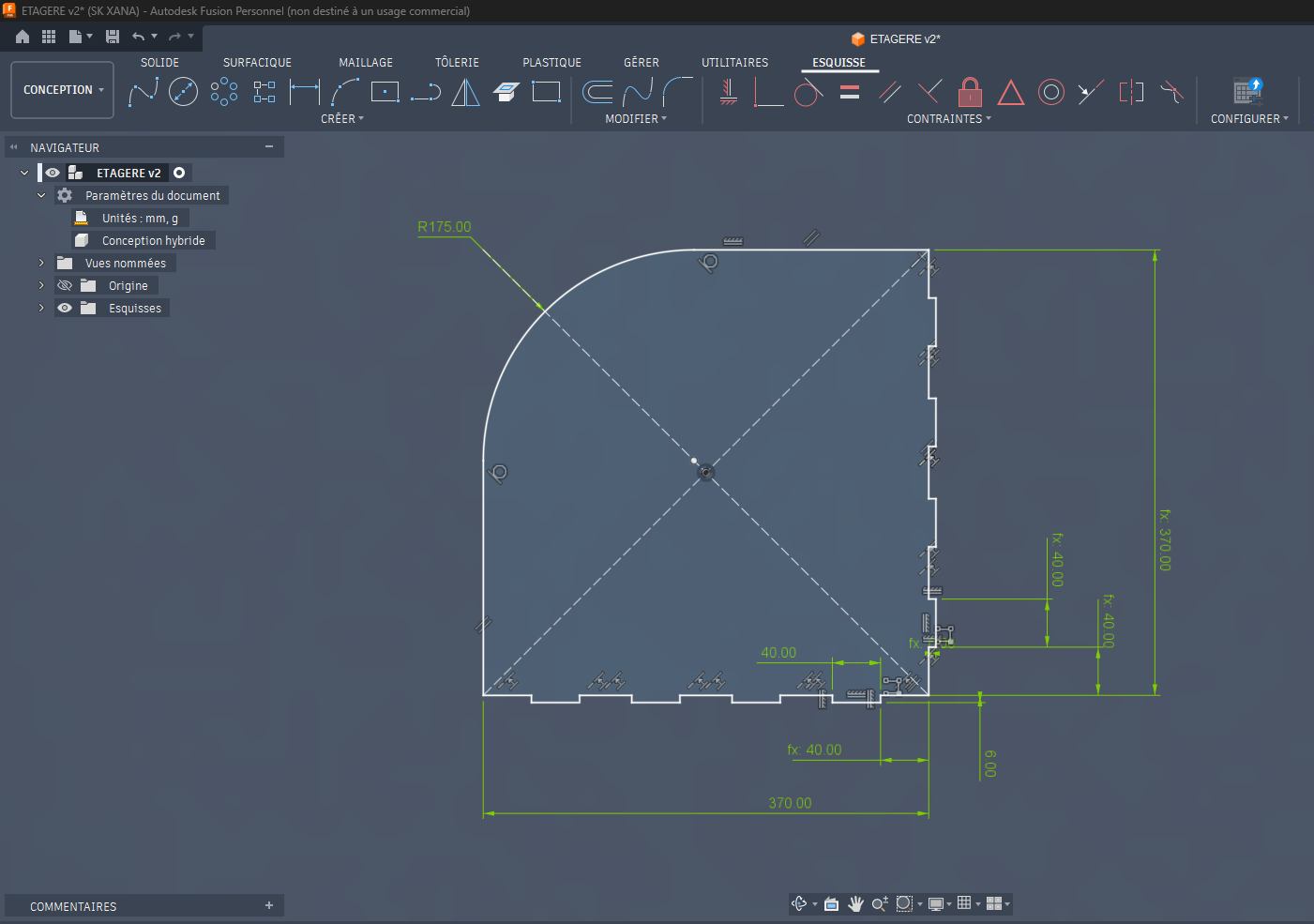
For aesthetic and safety reasons, the outer corner of each shelf features a pronounced rounded edge with a radius of 175 mm.
-
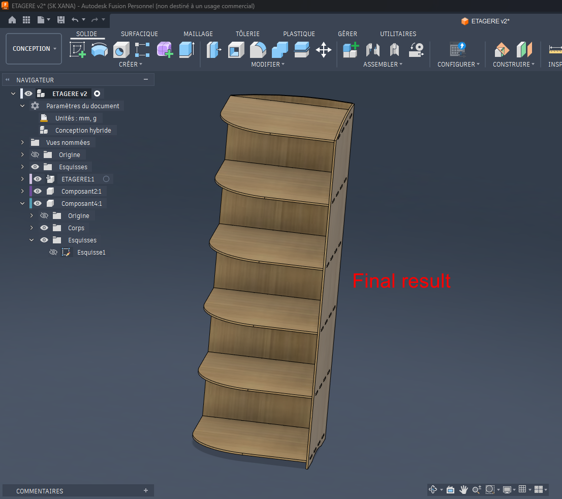
3D Modeling (CAD)
For the design of this piece of furniture, we used Autodesk Fusion 360. Its interface and parametric design logic are very similar to those of Onshape, which we explored during Week 2. If you wish to reproduce or adapt this project, we strongly recommend building on the skills acquired during that second week of training.
The structure was optimized for digital fabrication by focusing on the creation of two main components. Once these two parts are modeled, the rest of the furniture is generated using rectangular pattern features, ensuring perfect precision and easy modification of the overall dimensions.
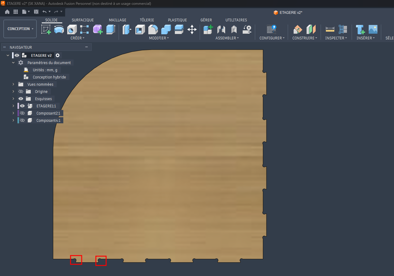
Sketch Details
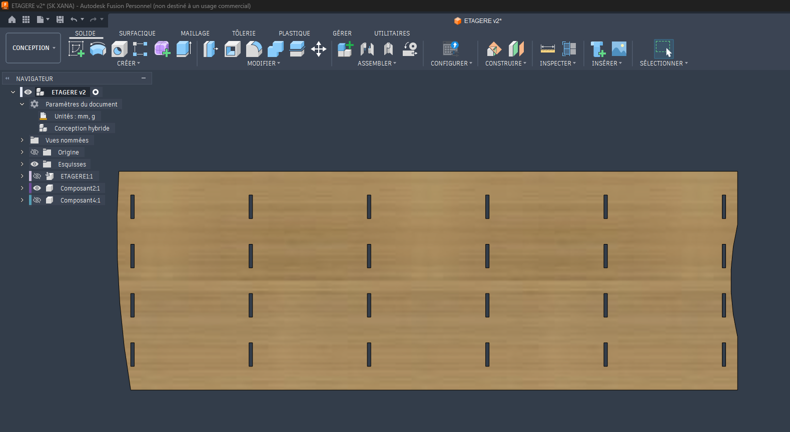
1. Part A: The Vertical Support
This part serves as the backbone of the furniture. It includes the slots (or mortises) designed to hold the shelves.
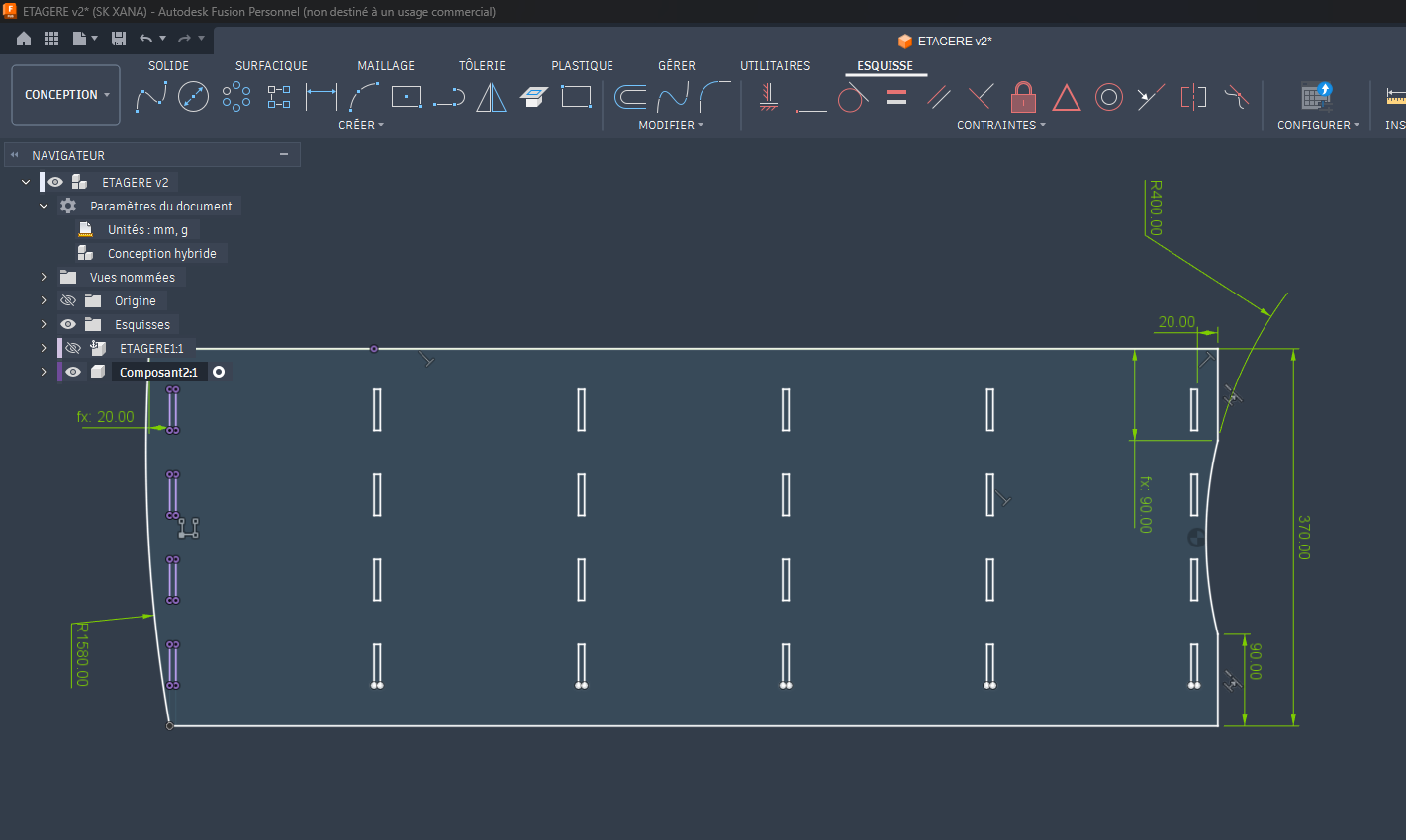
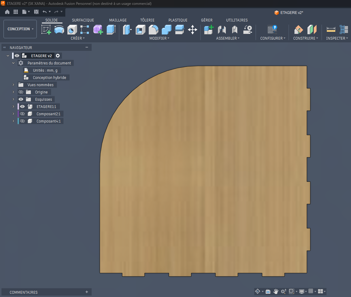
2. Part B: The Corner Shelf
This part is repeated five times. It follows dimensions of 370 × 370 mm with a characteristic rounded edge of 175 mm radius.
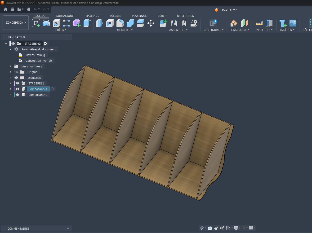
Virtual Assembly
Once the two main components were modeled, we proceeded with the assembly in the "Design" workspace of Fusion 360. This step is crucial, as it allows us to verify fitting tolerances and ensure that the 200 mm spacing between each level is perfectly maintained.
Export to .DXF Format (CAM Preparation)
Once the modeling and assembly were validated, it was necessary to “unfold” or project our parts into 2D so that the machine can follow the cutting paths. The .DXF (Drawing Exchange Format) is the universal standard for this operation.
Procedure in Fusion 360
-
Profile Preparation:
In the "Design" workspace, I created a new sketch on a clean construction plane. -
Projecting Contours:
Using the "Project" (P) tool, I selected the flat faces of each component (the vertical support and the shelves). This copies the edges of the 3D model onto the 2D sketch plane, including slots and fixing holes. -
Sketch Cleanup:
After projection, I checked that all lines were continuous and removed any unnecessary geometry that could interfere with toolpath generation. -
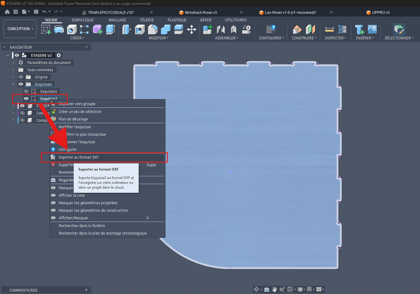
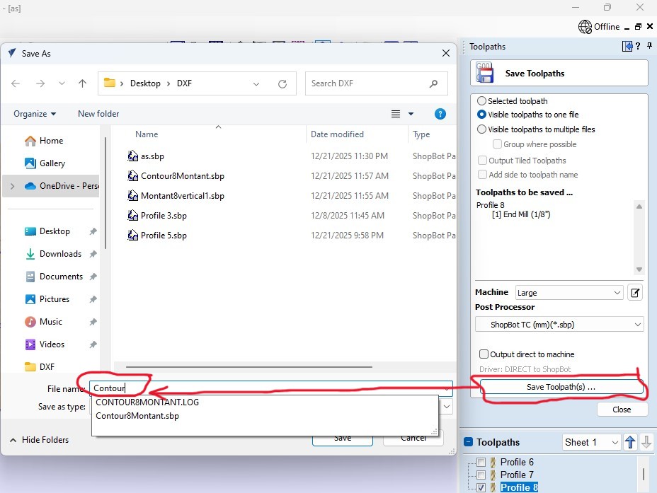
Exporting the File:
In the browser panel (left side), I right-clicked on the created sketch and selected "Save as DXF".
This file is then imported into CAM software (such as VCarve or Aspire, commonly used with the ShopBot) to generate machining strategies.
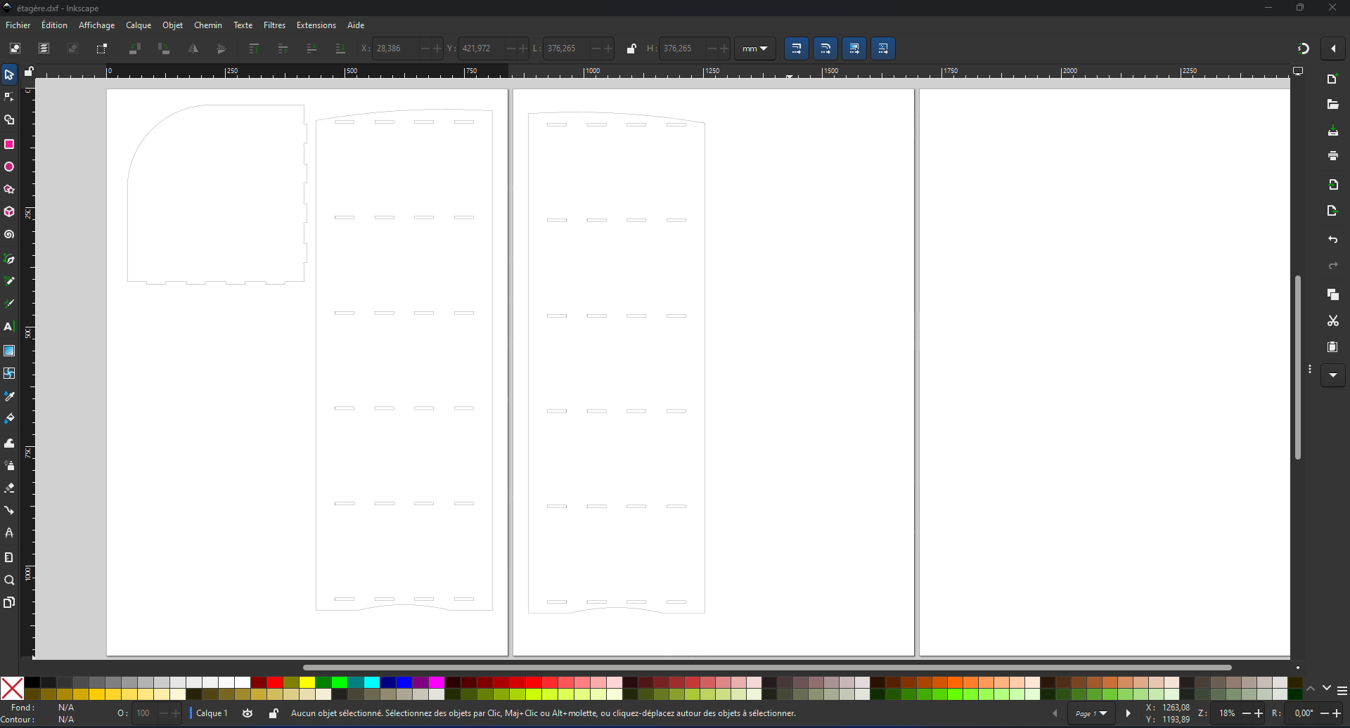
Optional Verification in Inkscape
You can also import your DXF files into Inkscape to preview the final 2D layout and make additional adjustments if necessary. This step is useful for:
- Verifying the visual appearance of the parts
- Checking alignment and proportions
- Making minor edits before CAM processing
Technical Tip:
Always export your files at a 1:1 scale. When importing into the ShopBot control software, double-check the overall dimensions to avoid scaling errors.
Toolpath Generation with VCarve
For the generation of toolpaths, we followed these steps:
-
Import the DXF File:
Open the exported .DXF file in VCarve. -
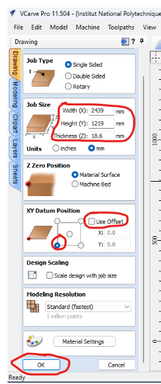
Machine Setup:
Enter the working dimensions of the ShopBot CNC machine.
Make sure to configure the job size according to your material dimensions. -
Offset Configuration:
Disable the offset option as shown below to ensure correct alignment between the design and the machining paths.
Once the files were exported, we proceeded to the nesting step. This phase consists of intelligently arranging the different parts on the virtual workspace representing our wooden panel.
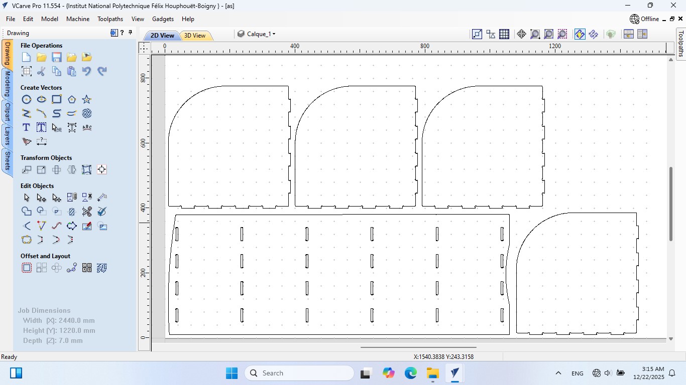
Cutting Toolpath Setup (2D Profile Toolpath)
For the final cutting of our parts, we configured an outside profile toolpath strategy.
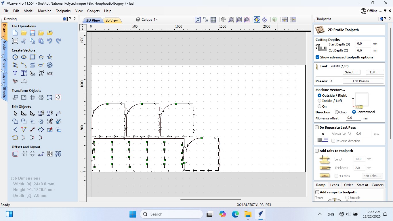
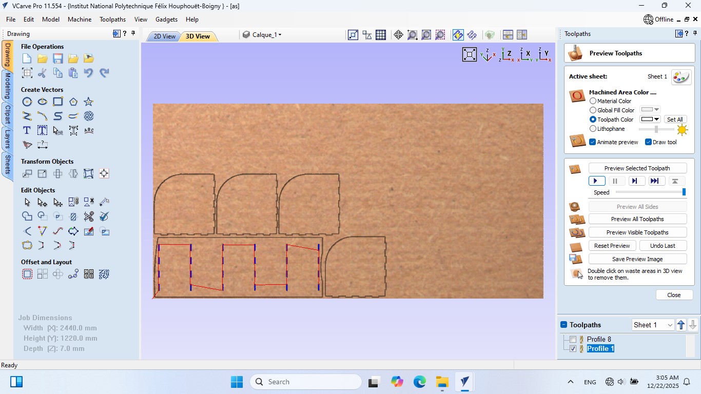
Profile Toolpath Configuration (2D Profile Toolpath)
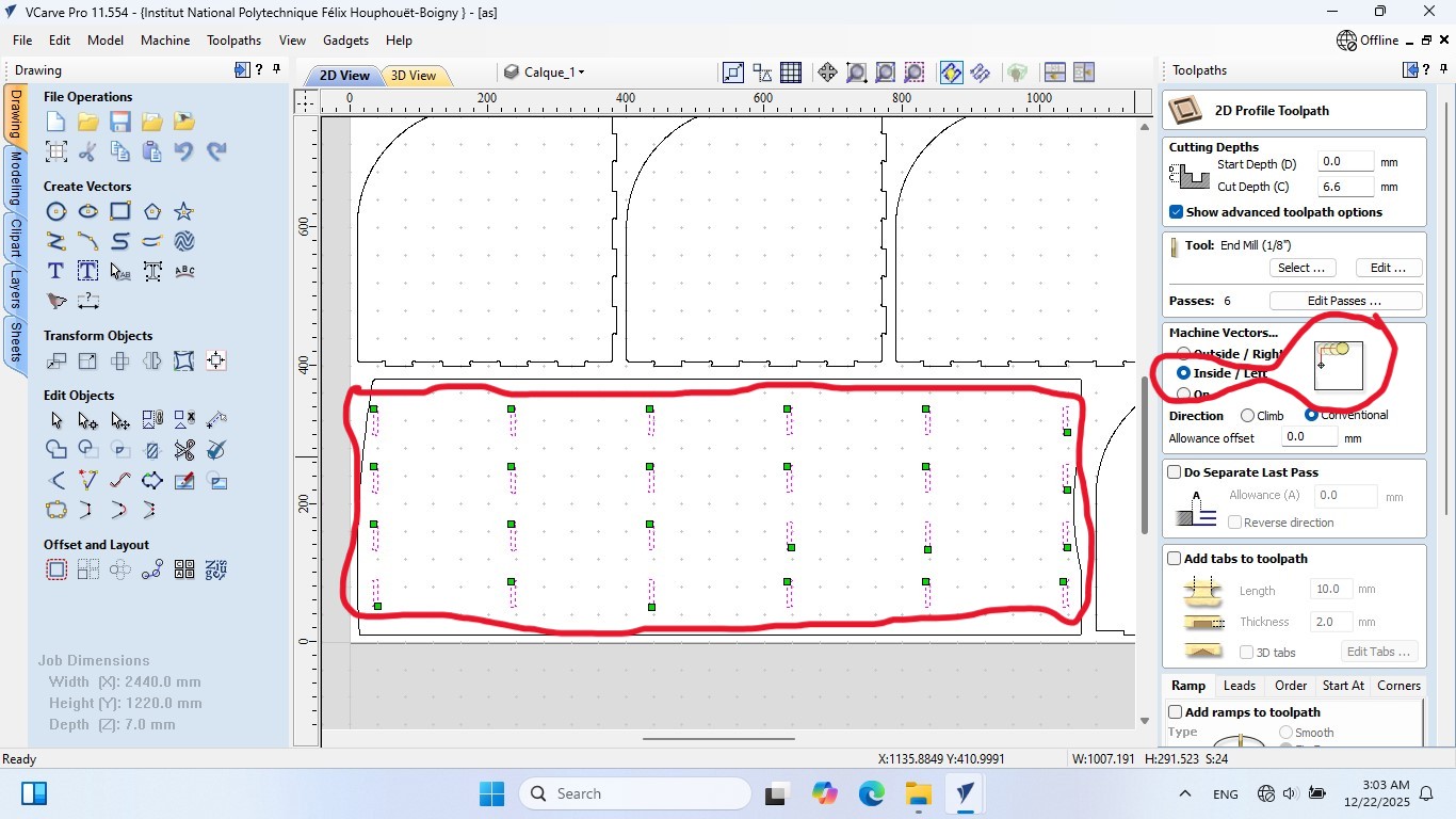
Based on the image of your configuration in VCarve Pro, here is the precise technical documentation of the parameters used for contour cutting.
Cutting Toolpath Setup (2D Profile Toolpath)
For the final cutting of our parts, we configured an outside profile toolpath strategy.
Procedure
-
Select All Contours:
Select all the outlines of your parts. -
Create the Toolpath:
Go to Toolpath > 2D Profile Toolpath, then choose Outside / Right to obtain an external cut. -
Cutting Depths:
- Start Depth: 0.0 mm (starting at the surface of the panel)
- Cut Depth: 6.6 mm
This value was chosen to cut through almost the entire 7.0 mm panel (as defined in the Job Dimensions), ensuring a clean cut.
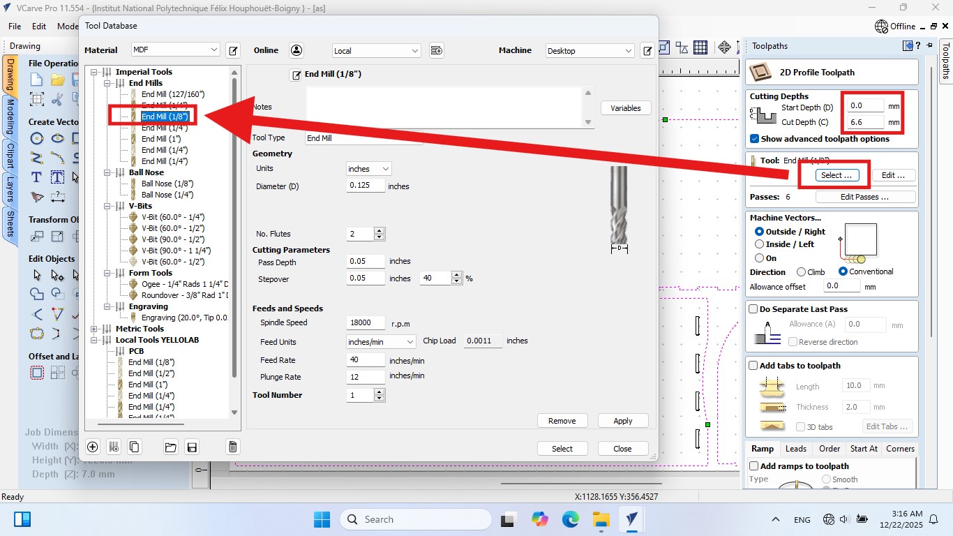
- Tool Selection:
We used an End Mill (⅛"), corresponding to a diameter of 3.175 mm.
This choice provides fine and precise cutting, ideal for the detailed features of our corner furniture.
- Calculate the Toolpath:
Click on Calculate to generate the toolpath.
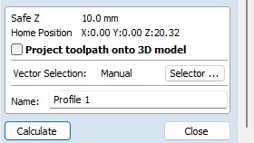
After this step, the following page will appear, displaying the generated toolpath preview.
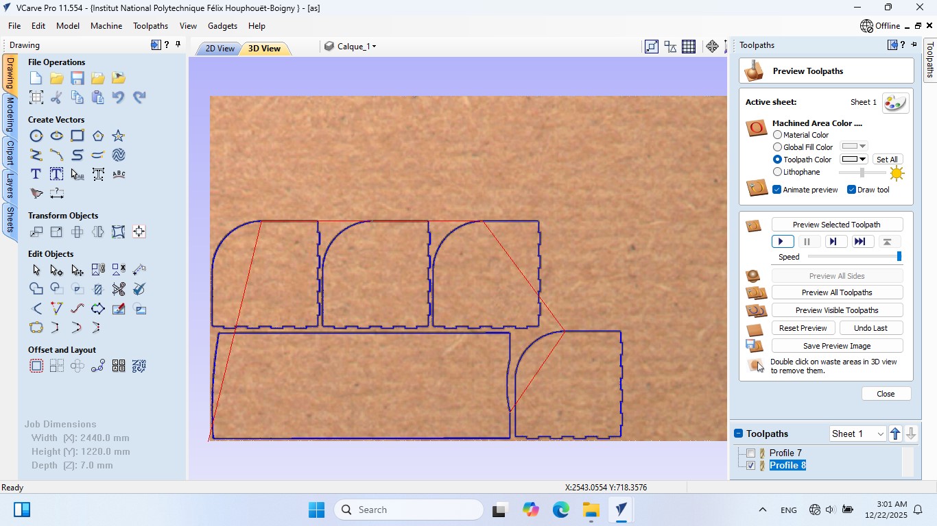
Go to Toolpath > 2D Profile Toolpath, then choose Inside / Right to obtain an external cut.
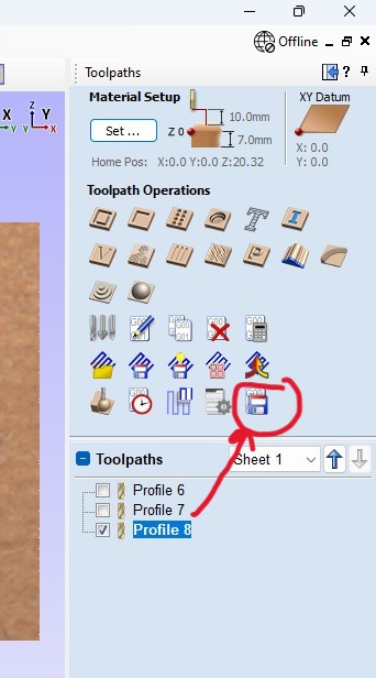
Important:
Do not forget to save your toolpath file, as shown in the previous steps.
Machining of the Dining Table
For the fabrication of the dining table, we used two tools, as described below.
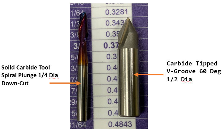
This photo was taken at the site of Koné Zié Souleymane
Machining Setup on the ShopBot Alpha 96
Once the programming is completed in VCarve Pro, we move on to the practical phase using the ShopBot Alpha 96. The first critical step is preparing the workspace.
To ensure precise and safe machining, we followed these steps:
-
Panel Installation:
We positioned our board (in this case MDF, although the project can also be adapted to plywood) on the sacrificial bed of the ShopBot. -
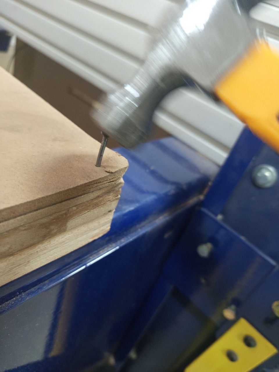
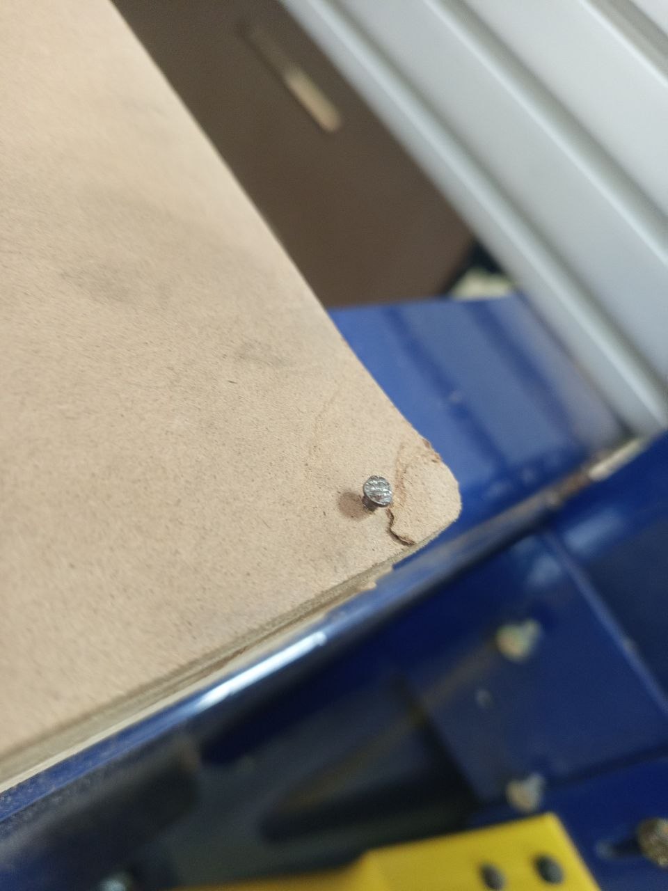
Mechanical Fixation:
Unlike other methods such as vacuum holding, we chose mechanical fastening using nails. -
Procedure:
Using a hammer, we secured the edges of the board onto the sacrificial bed. -
Major Precaution:
It is essential to ensure that the nails are placed outside the toolpath areas defined during the nesting step in VCarve, in order to avoid tool breakage or machine damage. -
Flatness Check:
We made sure that the board was perfectly flat against the sacrificial bed to prevent vibrations and inconsistencies in cutting depth.
For instructions on how to configure the Shopbot software, I will direct you to the website at DROH Koffi Sylvain
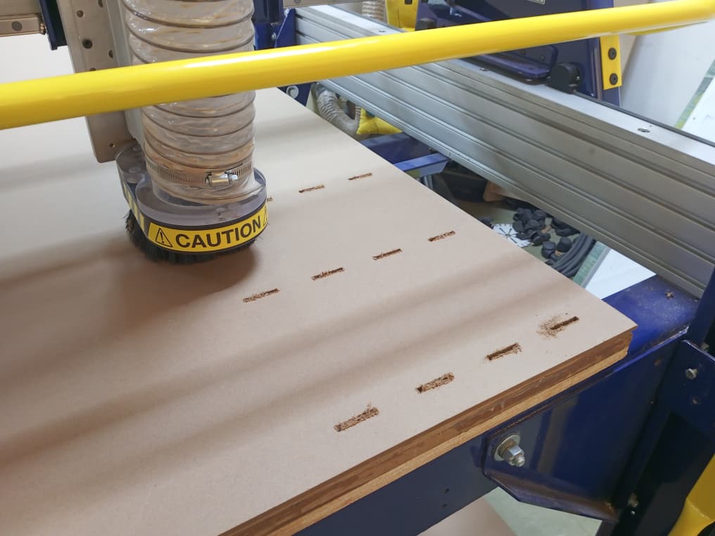
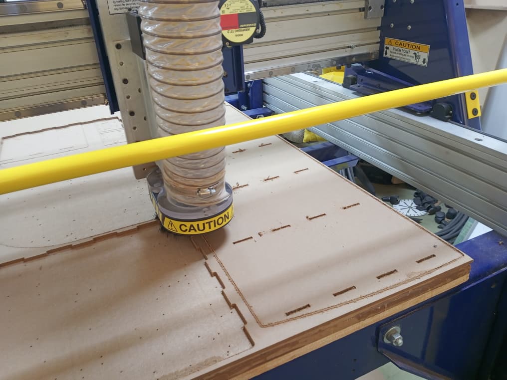
Machining and Final Assembly
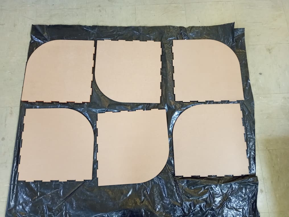
After setting the origins (X, Y, and Z), we started the machining process on the ShopBot Alpha 96. The machine first cleared the mortises and then proceeded to cut the profiles at a depth of 6.6 mm.
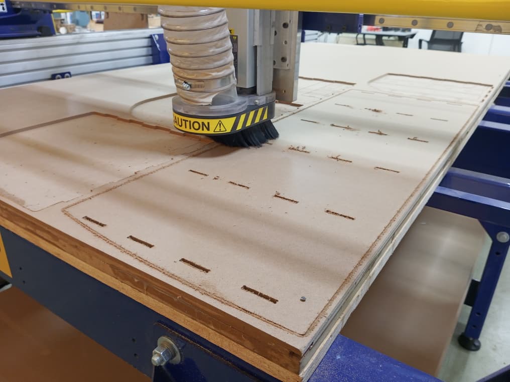
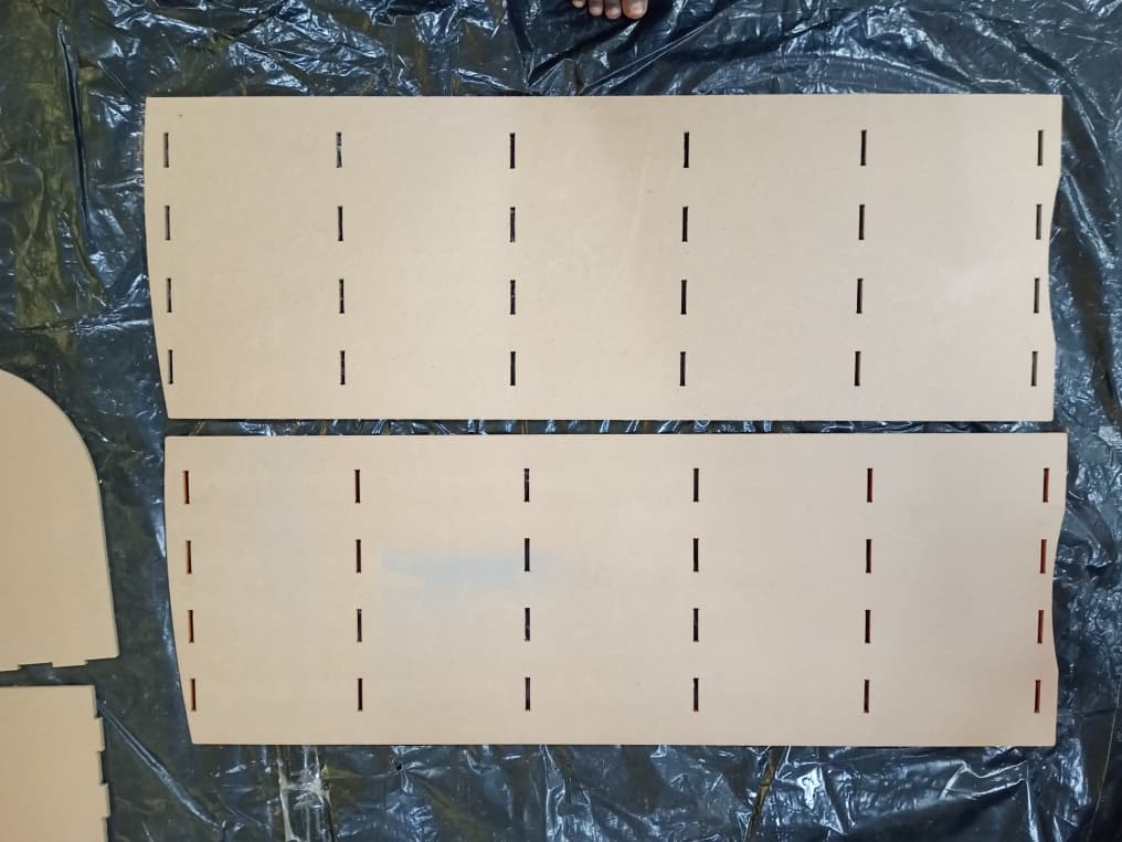
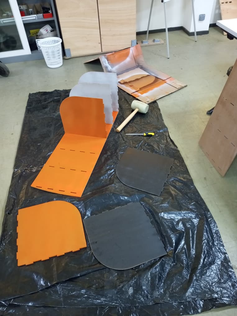
Once the cutting was complete, we removed the parts by cutting the tabs and lightly sanded the edges to ensure a smooth finish.
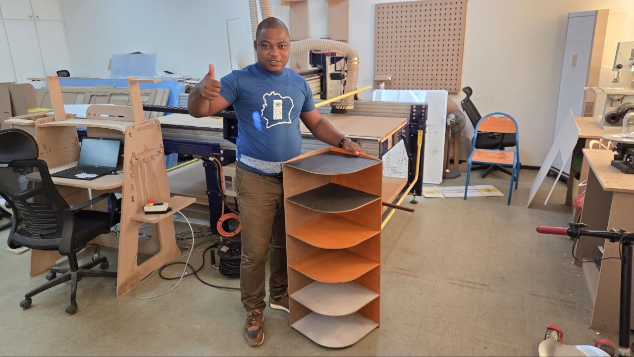
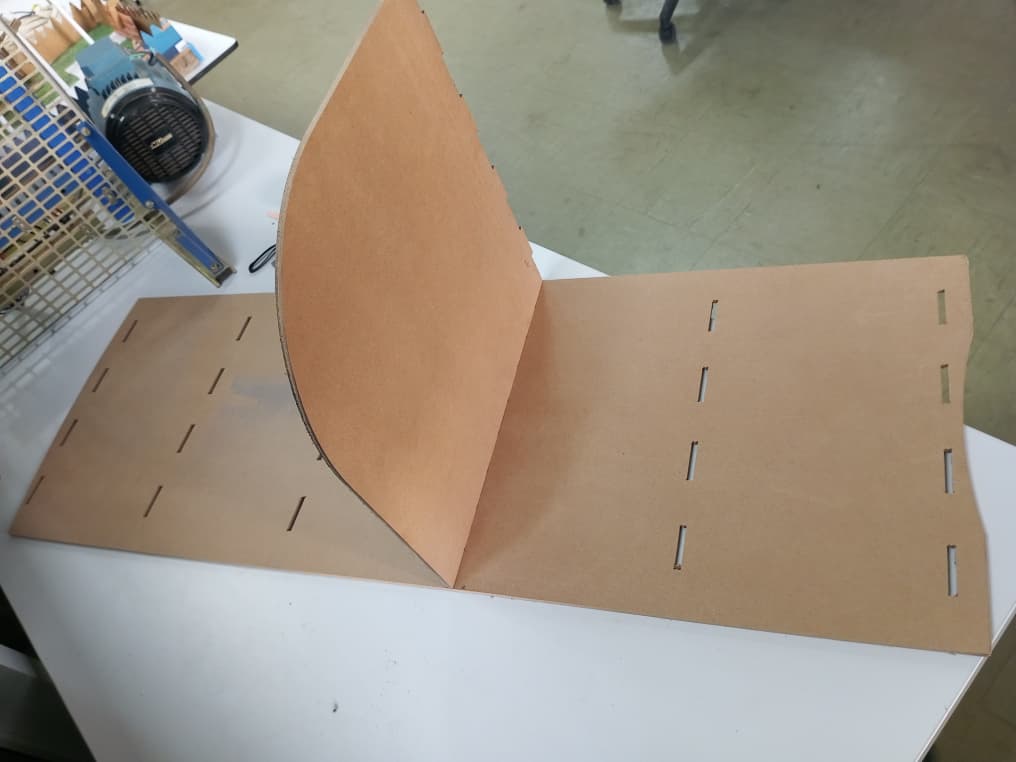
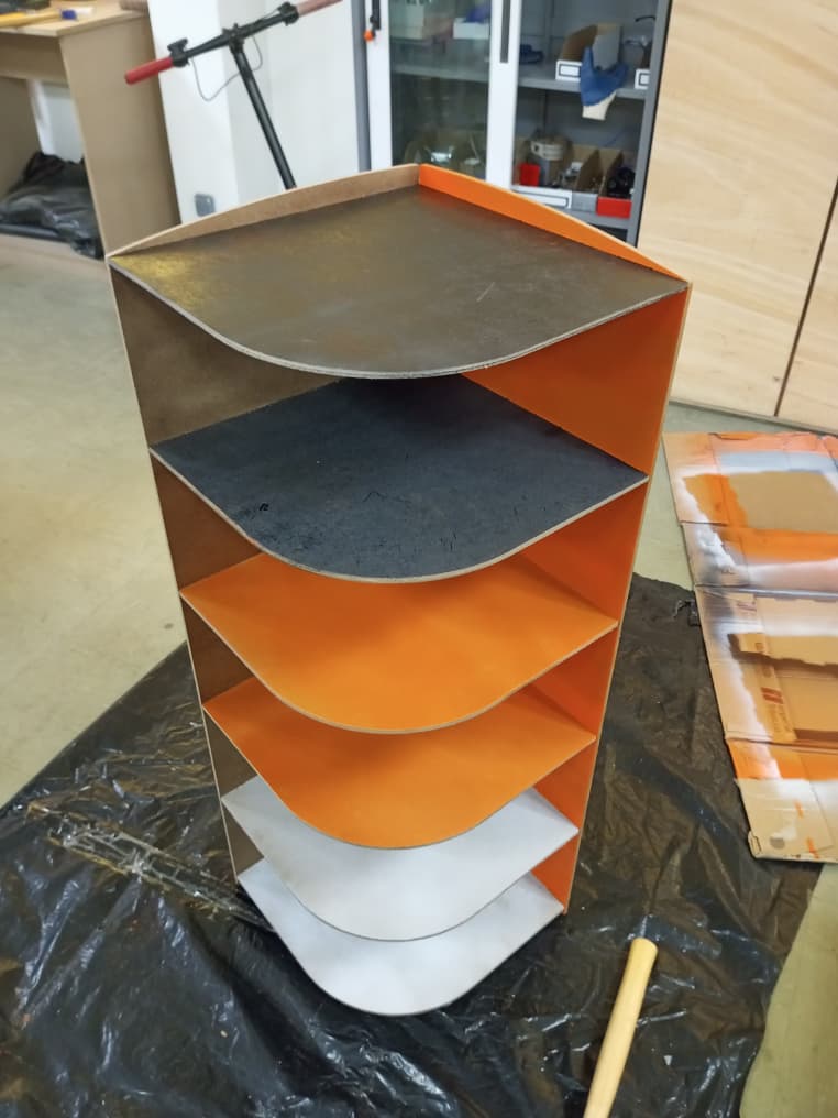
The assembly was done by interlocking the pieces. Thanks to the use of the NiftyDogboneFusion script during the design phase, the supports and the 5 rounded shelves (370 x 370 mm) fit together perfectly without any interference in the corners. The final result strictly adheres to the planned 1000 mm height.
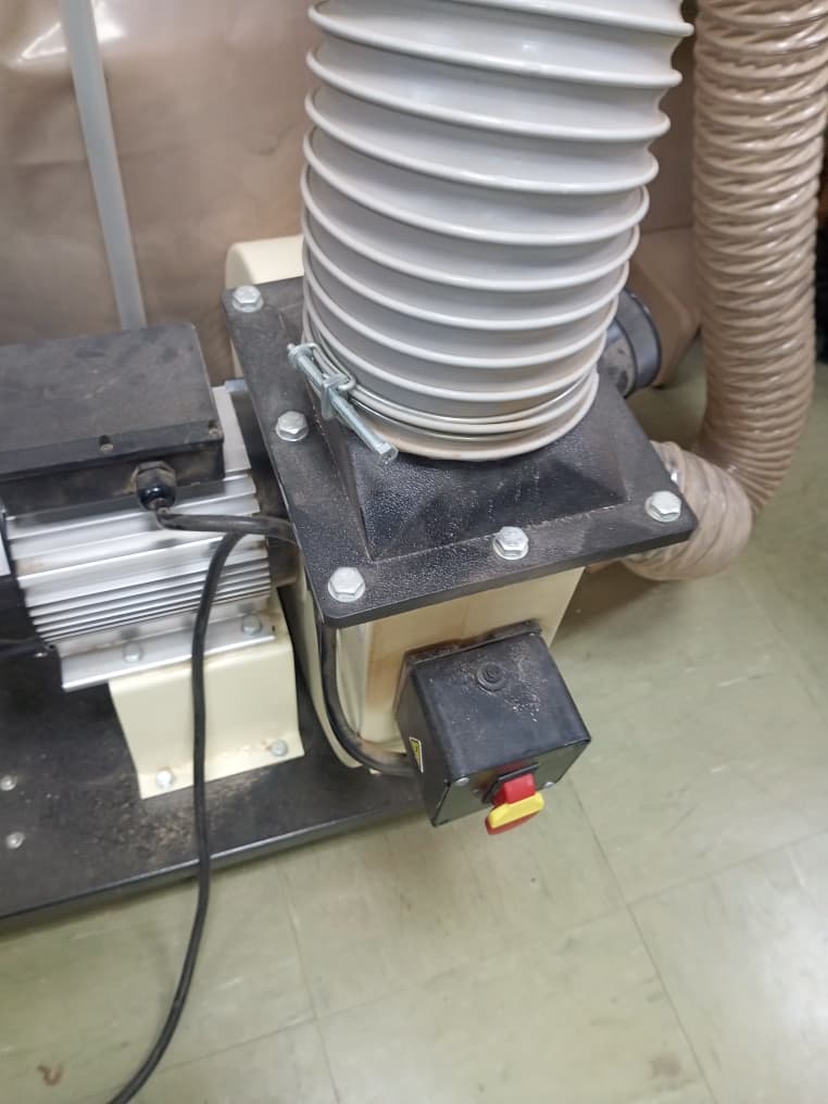
Important:
Do not forget to turn on the dust collector by lifting the lever, as shown in the image, to ensure proper chip evacuation and maintain a clean and safe working environment.
HERO SHOTS 😊😊😊