Skip to content

9. Input devices

Group assignment:

  • Probe an input device(s)'s analog and digital signals

  • Document your work on the group work page and reflect on your individual page what you learned

To see our group assignment click here

Individual assignment:

  • measure something : add a sensor to a microcontroller board that you have designed and read it.

Introduction to the project
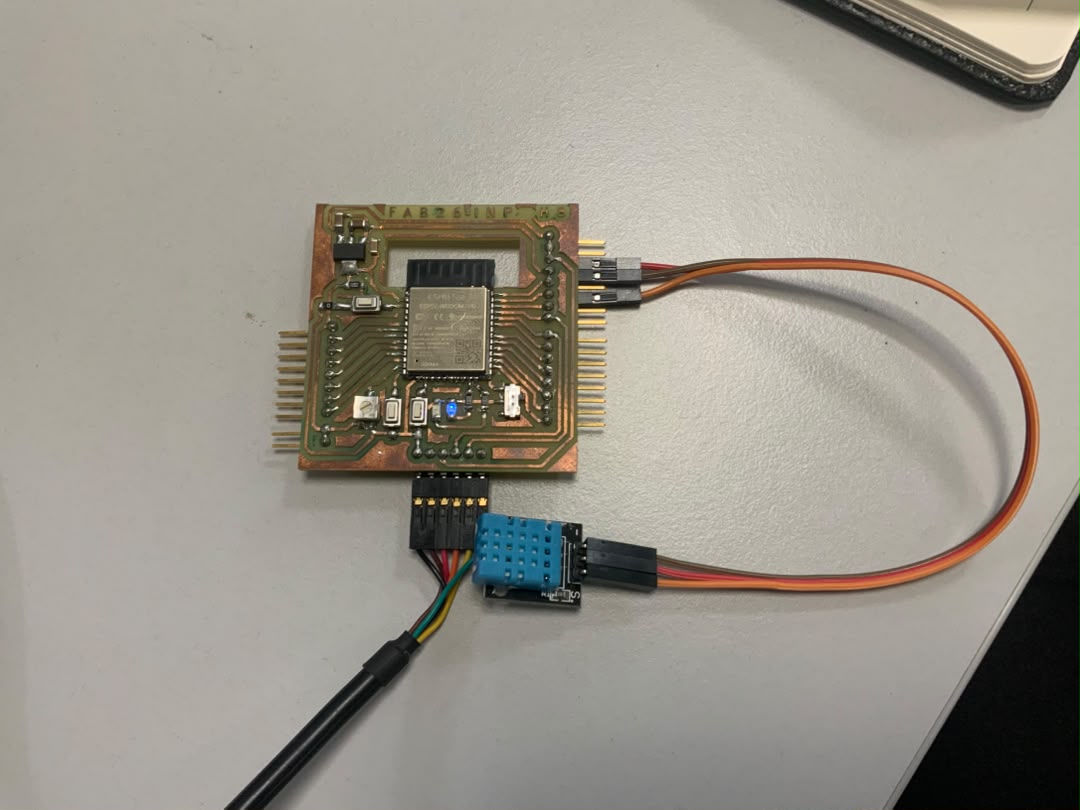
For this week focused on Input Devices, I decided to build a compact monitoring station using my custom ESP32 board. The project involves acquiring environmental data (temperature and humidity) via the DHT11 sensor, while allowing for physical user interaction. The potentiometer is used to manually set an adjustable alert threshold, and the pushbutton allows the user to toggle displays or reset an alarm.

Presentation of the DHT11 Sensor

Image

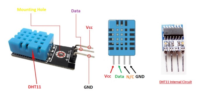
The DHT11 is a low-cost digital sensor used to measure temperature and humidity. It is widely used in electronics projects, especially with platforms such as Arduino, ESP32, and Raspberry Pi, due to its simplicity and ease of integration.

DHT11 Sensor Specifications

Parameter Value
Temperature Range 0°C to 50°C
Temperature Accuracy ±2°C
Humidity Range 20% to 80%
Humidity Accuracy ±5%
Output Signal Digital
Operating Voltage 3.3V to 5V
Sampling Rate 1 Hz (1 reading per second)
Power Consumption Low
Communication Protocol Single-wire digital
Response Time Slow
Cost Low

DHT11 Working Principle

The DHT11 is a composite digital sensor capable of measuring both temperature and ambient humidity. Unlike simple analog sensors, it integrates its own signal processing system.

1. Internal Components

The blue casing of the DHT11 contains three main elements:

  • Resistive humidity sensor:
    It consists of two electrodes with a moisture-retaining substrate (usually a polymer) between them.

  • NTC thermistor:
    A resistor whose value varies predictably with temperature.

  • 8-bit microcontroller:
    It measures the variations from both sensors, performs analog-to-digital conversion, and transmits the data.

2. Humidity Measurement

The working principle is based on electrical conductivity:

  • When the humidity level changes, the substrate between the electrodes absorbs water vapor.
  • This alters the electrical resistance between the electrodes.
  • The internal microcontroller measures this variation to calculate the relative humidity (%).

3. Temperature Measurement

The DHT11 uses a Negative Temperature Coefficient (NTC) thermistor:

  • Its resistance decreases as temperature increases.
  • The microcontroller converts this resistance value into a temperature reading in degrees Celsius (°C).

Components

Our custom board and other components for the project

Image

Image

Wiring diagram

Image

Power Connection (VCC)

Connect the VCC pin of the sensor to the 3.3V pin to power the DHT11.

Using 3.3V instead of 5V ensures that the digital signal sent to the GPIO does not exceed the maximum voltage supported by the ESP32. This helps prevent damaging the microcontroller’s input.

DHT Sensor Library

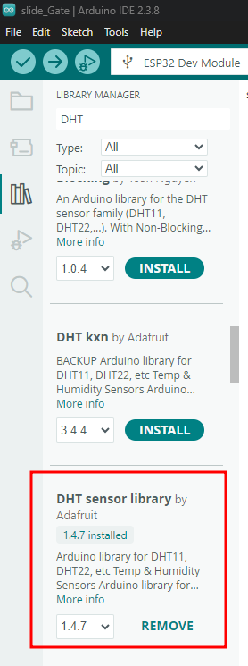
To use the DHT11 easily with Arduino, you need to install the "DHT sensor library".

Installing the Library in Arduino IDE

To add a library in the Arduino IDE:

  1. Go to the menu Tools → Manage Libraries
  2. Search for "DHT sensor library"
  3. Click Install

This library simplifies communication with the DHT11 sensor by handling the data acquisition and decoding process.

Next, simply search for and add the DHT sensor library from Adafruit.

Image

Croquis

The Arduino sketch (program) is very simple thanks to the DHT sensor library.

You can upload it to see how the DHT11 sensor responds.

Image

Image

Project code

````markdown id="esp32dhtcode"

#include <DHT11.h>

// ESP32 pin definitions
#define DHTPIN 27
#define POT_PIN 14
#define BUTTON_PIN 12

// Initialize the DHT11 sensor
DHT11 dht11(DHTPIN); 

// Global variables for display management
bool displayHumidityMode = false; 
bool lastButtonState = HIGH;

void setup() {
  // Initialize Serial Monitor at 115200 baud
  Serial.begin(115200);

  // Configure the button pin with internal pull-up resistor
  pinMode(BUTTON_PIN, INPUT_PULLUP);

  Serial.println("--- Monitoring Station (Inputs Only) Ready ---");
}

void loop() {

  // --- 1. INPUT READING ---

  int temp = 0;
  int hum = 0;

  // Read temperature and humidity from the DHT11
  int dhtResult = dht11.readTemperatureHumidity(temp, hum);

  // Analog reading from the potentiometer (0 to 4095)
  int potVal = analogRead(POT_PIN);

  // Digital reading from the push button
  // LOW = pressed, HIGH = released
  bool currentButtonState = digitalRead(BUTTON_PIN);

  // --- 2. INPUT PROCESSING ---

  // A. Potentiometer processing:
  // Convert raw value into a temperature threshold (20°C to 40°C)
  float alertThreshold = map(potVal, 0, 4095, 20, 40);

  // B. Push button processing:
  // Detect button press (falling edge) to switch display mode
  if (currentButtonState == LOW && lastButtonState == HIGH) {

    displayHumidityMode = !displayHumidityMode;

    Serial.println("\n[Action] Button pressed: Display mode changed!");

    // Software debounce
    delay(50);
  }

  // Save button state for next loop
  lastButtonState = currentButtonState;

  // --- 3. DATA DISPLAY (SERIAL MONITOR) ---

  if (dhtResult == 0) {

    Serial.print("Set Threshold (Potentiometer): ");
    Serial.print(alertThreshold);
    Serial.print("°C | ");

    // Display mode selection based on button state
    if (displayHumidityMode) {

      Serial.print("Display: HUMIDITY = ");
      Serial.print(hum);
      Serial.println("%");

    } else {

      Serial.print("Display: TEMPERATURE = ");
      Serial.print(temp);
      Serial.print("°C");

      // Text alert if temperature exceeds threshold
      if (temp > alertThreshold) {
        Serial.print(" -> [ALERT: Threshold Exceeded!]");
      }

      Serial.println();
    }

  } else {

    Serial.println("Error: Unable to read the DHT11 sensor.");
  }

  // Refresh delay
  delay(200);
}
````markdown id="esp32dhexplain"

## **Brief Explanation of the Code**

### 1. Library Inclusion

```cpp
#include <DHT11.h>

This line imports the DHT11 library, which allows easy communication with the sensor.


2. Pin Definitions

#define DHTPIN 27
#define POT_PIN 14
#define BUTTON_PIN 12

These lines define the ESP32 pins connected to:

  • The DHT11 sensor
  • The potentiometer
  • The push button

3. Sensor Initialization

DHT11 dht11(DHTPIN);

This creates a DHT11 object linked to pin 27.


4. Global Variables

bool displayHumidityMode = false;
bool lastButtonState = HIGH;

These variables are used to:

  • Switch between temperature and humidity display
  • Store the previous button state for button press detection

5. Setup Function

void setup()

The setup function runs once when the ESP32 starts.

It:

  • Initializes the Serial Monitor
  • Configures the button pin as an input with an internal pull-up resistor

6. Reading Inputs

dht11.readTemperatureHumidity(temp, hum);
analogRead(POT_PIN);
digitalRead(BUTTON_PIN);

The ESP32 reads:

  • Temperature and humidity from the DHT11
  • The potentiometer value
  • The push button state

7. Potentiometer Processing

map(potVal, 0, 4095, 20, 40);

The potentiometer value is converted into a temperature threshold between 20°C and 40°C.


8. Button Management

if (currentButtonState == LOW && lastButtonState == HIGH)

This detects when the button is pressed and changes the display mode between:

  • Temperature
  • Humidity

9. Data Display

Serial.print(...)

The measured values and system status are displayed in the Serial Monitor.


10. Temperature Alert

if (temp > alertThreshold)

If the measured temperature exceeds the threshold set by the potentiometer, an alert message is displayed.


11. Refresh Delay

delay(200);

The system waits 200 ms before repeating the loop.


Result After Uploading the Code

The following result was obtained after uploading the program to the ESP32 board.


Files

Download Code files