10. Output devices
Group assignment:
-
Measure the power consumption of an output device.
-
Document your work to the group work page and reflect on your individual page what you learned
To see our group assignment click here
Individual assignment:
- Add an output device to a microcontroller board you've designed and program it to do something.
What I observed from the power consumption measurement
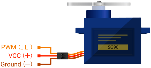
For this group assignment, we measured the power consumption of the SG90 servo motor controlled by an ESP32, using a stabilized lab power supply while the servo swept continuously from 0° to 180°. The current draw varied between 0.06 A and 0.11 A, depending on whether the servo was holding a position or actively moving — the current peaks were observed during movement, when the motor needs more torque to overcome mechanical resistance and inertia, while the lower values corresponded to moments when the servo was nearly stationary. At a supply voltage of 5V, this translates to a power consumption of roughly 0.3 W to 0.55 W.
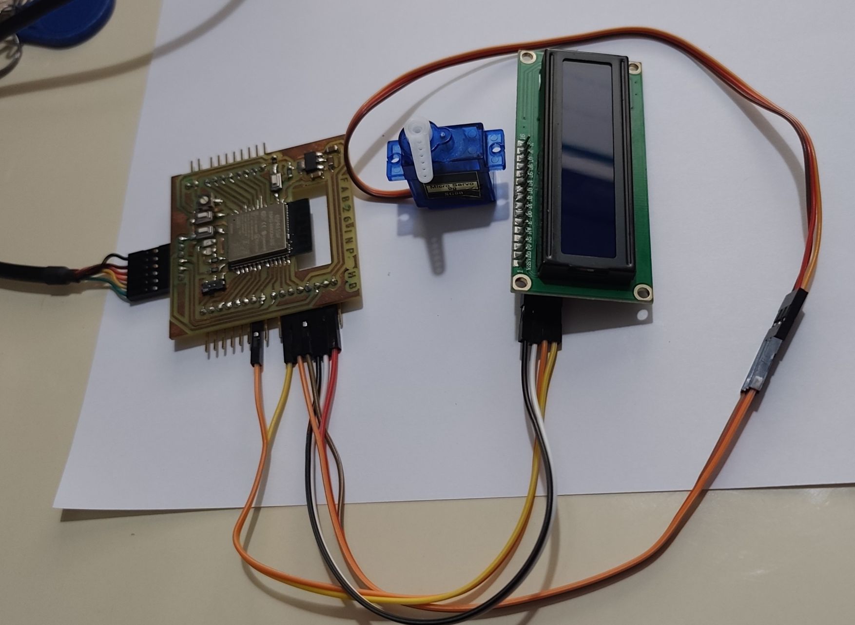
Introduction to the project
The project utilizes an I2C LCD screen for a visual interface and a servomotor for motion control.
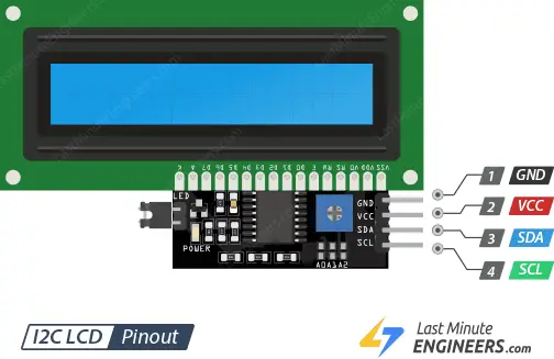
The LCD Display 16x02
The 16x2 LCD display (via I2C) serves as a Human-Machine Interface (HMI). Its role is to translate the processor’s internal data into readable text messages, allowing the user to monitor the system status in real time.
The LCD display acts as the bridge between the computer program (invisible) and the user. In automation systems, a machine should always indicate what it is doing.
Since the project uses a servo motor, the LCD also serves to validate the command sent to the motor.
It displays the setpoint value transmitted by the ESP32, making it possible to verify that the mechanical movement correctly matches the logical value calculated by the microcontroller.
Servomotor
Unlike a conventional motor, which runs continuously, the servomotor is designed to move to a specific position and hold it there.
In our system, it acts as the mechanical actuator. Its role is to convert a logical command into an actual physical movement.
Wiring diagram
| Component | Component pin | ESP32 pin |
|---|---|---|
| LCD VCC | VCC | 5V |
| LCD GND | GND | GND |
| LCD SDA | SDA | GPIO 21 |
| LCD SCL | SCL | GPIO 22 |
| SERVO VCC | VCC | 5V |
| SERVO GND | GND | GND |
| SERVO DATA | DATA | GPIO 23 |
Project code
#include <Wire.h>
#include <LiquidCrystal_I2C.h>
#include <ESP32Servo.h>

// 1. Configuration de l'écran LCD (Adresse 0x27 ou 0x3F, 16 colonnes, 2 lignes)
LiquidCrystal_I2C lcd(0x27, 16, 2);

// 2. Configuration du Servomoteur
Servo monServo;
#define SERVO_PIN 23  // Broche de sortie pour le servomoteur

void setup() {
  // Initialisation du LCD
  lcd.init();
  lcd.backlight();

  // Initialisation du Servomoteur
  ESP32PWM::allocateTimer(0); // Allocation du timer pour l'ESP32
  monServo.setPeriodHertz(50); // Fréquence standard de 50Hz pour un servo
  monServo.attach(SERVO_PIN, 500, 2400); // Attache la broche avec les limites de signal (min, max)

  // Message d'accueil
  lcd.setCursor(0, 0);
  lcd.print("SYSTEME OUTPUT");
  lcd.setCursor(0, 1);
  lcd.print("INITIALISATION...");
  delay(2000);
  lcd.clear();
}

void loop() {
  // --- SEQUENCE 1 : Position 0 degres ---
  lcd.setCursor(0, 0);
  lcd.print("ETAT: REPOS     ");
  lcd.setCursor(0, 1);
  lcd.print("ANGLE: 0 deg    ");
  monServo.write(0);
  delay(2000);

  // --- SEQUENCE 2 : Position 90 degres ---
  lcd.setCursor(0, 0);
  lcd.print("ETAT: MI-OUVERT ");
  lcd.setCursor(0, 1);
  lcd.print("ANGLE: 90 deg   ");
  monServo.write(90);
  delay(2000);

  // --- SEQUENCE 3 : Position 180 degres ---
  lcd.setCursor(0, 0);
  lcd.print("ETAT: MAXIMAL   ");
  lcd.setCursor(0, 1);
  lcd.print("ANGLE: 180 deg  ");
  monServo.write(180);
  delay(2000);
}
General Explanation of the Code
1. Library Inclusion
These libraries provide the main functionalities of the project:
- Wire.h → Enables I2C communication, used by the LCD screen
- LiquidCrystal_I2C.h → Controls the 16x2 LCD display through the I2C bus
- ESP32Servo.h → Allows precise servomotor control on the ESP32 (since the standard
Servo.hlibrary is not fully compatible with the ESP32)
2. LCD and Servo Configuration
lcdcreates an LCD object at I2C address 0x27 (a common default address; 0x3F is used on some other modules), configured for 16 columns and 2 rows.monServocreates a Servo object used to control the motor.SERVO_PINdefines GPIO 23 as the output pin connected to the servomotor's signal wire.
3. Setup Function
void setup() {
  lcd.init();
  lcd.backlight();

  ESP32PWM::allocateTimer(0);
  monServo.setPeriodHertz(50);
  monServo.attach(SERVO_PIN, 500, 2400);

  lcd.setCursor(0, 0);
  lcd.print("SYSTEME OUTPUT");
  lcd.setCursor(0, 1);
  lcd.print("INITIALISATION...");
  delay(2000);
  lcd.clear();
}
The setup function initializes the whole system:
lcd.init()andlcd.backlight()start the LCD screen and turn on its backlight.ESP32PWM::allocateTimer(0)reserves a hardware PWM timer, required by the ESP32Servo library to generate the servo control signal.monServo.setPeriodHertz(50)sets the signal frequency to 50 Hz, the standard value for analog servomotors.monServo.attach(SERVO_PIN, 500, 2400)attaches the servo to its pin and defines the pulse width range (500–2400 µs), which corresponds to the servo's 0°–180° travel.- A welcome message ("SYSTEME OUTPUT" / "INITIALISATION...") is displayed on the LCD for 2 seconds before the screen is cleared.
4. Main Loop
void loop() {
  // Sequence 1: 0 degres
  lcd.setCursor(0, 0);
  lcd.print("ETAT: REPOS     ");
  lcd.setCursor(0, 1);
  lcd.print("ANGLE: 0 deg    ");
  monServo.write(0);
  delay(2000);

  // Sequence 2: 90 degres
  lcd.setCursor(0, 0);
  lcd.print("ETAT: MI-OUVERT ");
  lcd.setCursor(0, 1);
  lcd.print("ANGLE: 90 deg   ");
  monServo.write(90);
  delay(2000);

  // Sequence 3: 180 degres
  lcd.setCursor(0, 0);
  lcd.print("ETAT: MAXIMAL   ");
  lcd.setCursor(0, 1);
  lcd.print("ANGLE: 180 deg  ");
  monServo.write(180);
  delay(2000);
}
The main loop continuously repeats a 3-step sequence, each lasting 2 seconds:
| Step | Servo angle | LCD Line 1 | LCD Line 2 |
|---|---|---|---|
| 1 | 0° | ETAT: REPOS | ANGLE: 0 deg |
| 2 | 90° | ETAT: MI-OUVERT | ANGLE: 90 deg |
| 3 | 180° | ETAT: MAXIMAL | ANGLE: 180 deg |
For each step, the code:
- Updates the two lines of the LCD screen (
lcd.setCursor+lcd.print) to show the current state and angle. - Sends the corresponding position command to the servomotor with
monServo.write(angle). - Waits 2 seconds (
delay(2000)) before moving to the next step.