Project Development
This section documents the complete development process of my final project — from the initial sketch to the assembly and testing of the finished system.
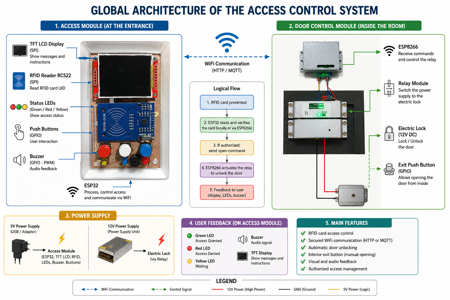
The project is a Smart Access Control System for the FabLab, which grants entry only to registered members via an RFID badge and logs all entries and exits through a web interface.
01. Sketch and System Architecture
The project was designed around two main functional units:
-
The Access Module — mounted at the FabLab entrance, it houses the RFID reader, buzzer, and LED indicators.
-
The Door Control Module — mounted inside the FabLab, it houses the relay and the electrically controlled door lock.
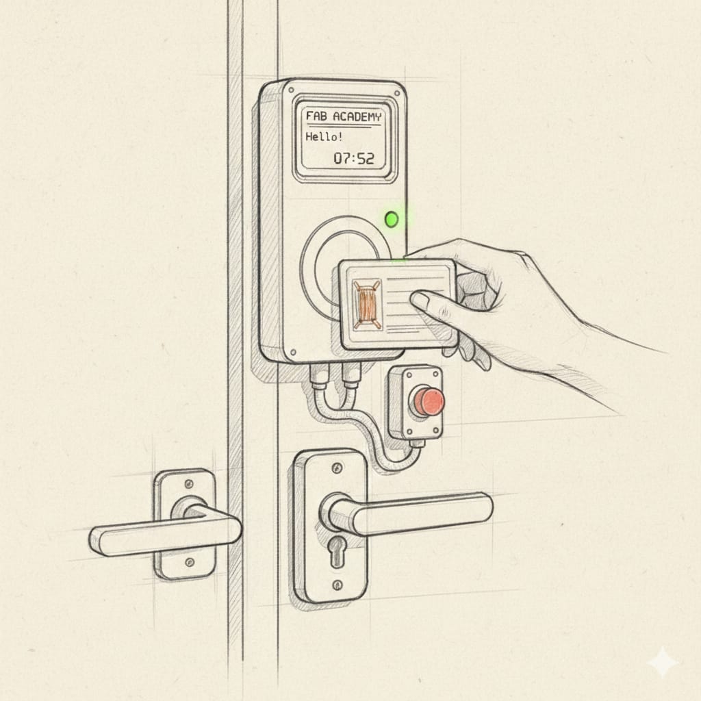
Below is the initial concept sketch of the system:
The diagram below illustrates the overall architecture of the system:
02. Design of the Enclosure
For the 3D design of the device enclosure, I used SolidWorks.
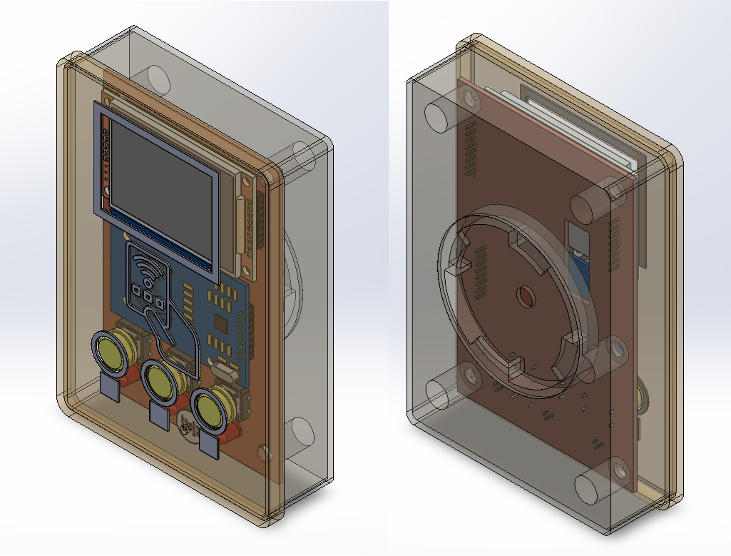
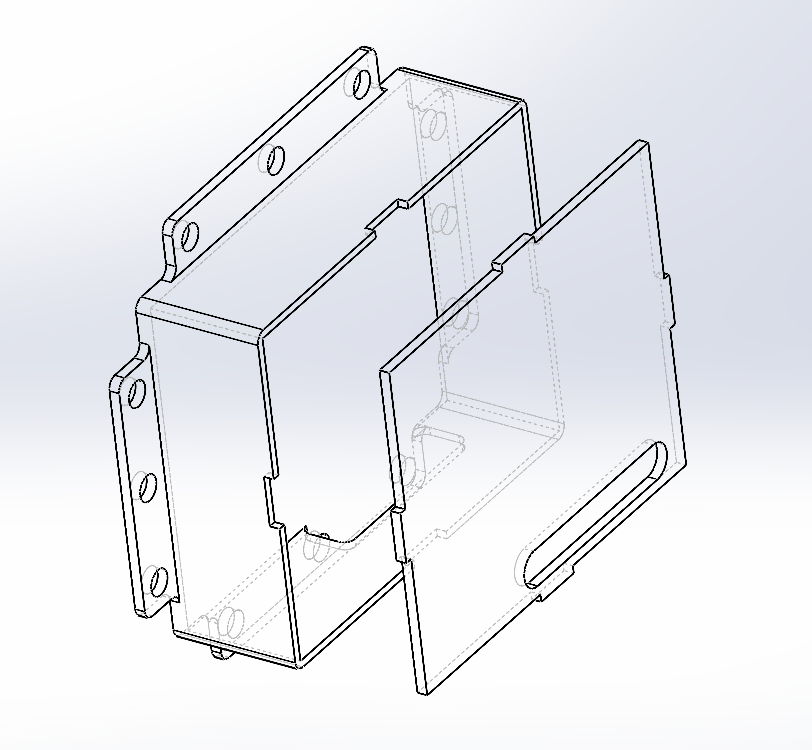
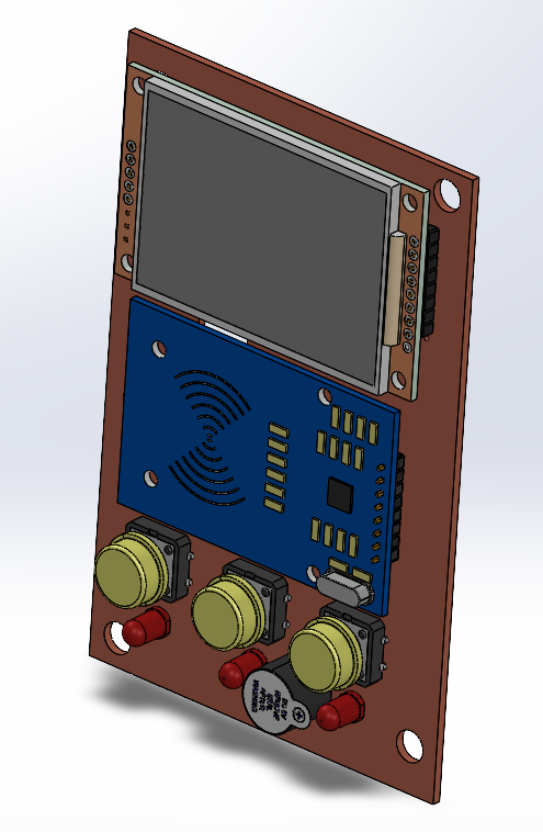
Outdoor Access Module
The enclosure is made up of two parts:
- The main shell — houses the ESP32 PCB, the RFID reader, LCD screen, LEDs, and buzzer
- The cover — closes the enclosure
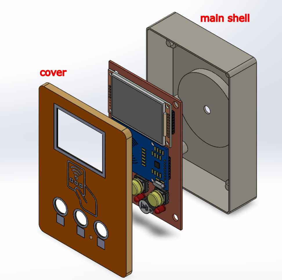
Design files:
Indoor Door Control Module
The enclosure is made up of two parts:
- The main shell — houses the ESP8266 and the relay module
- The cover — closes the enclosure
Design files:
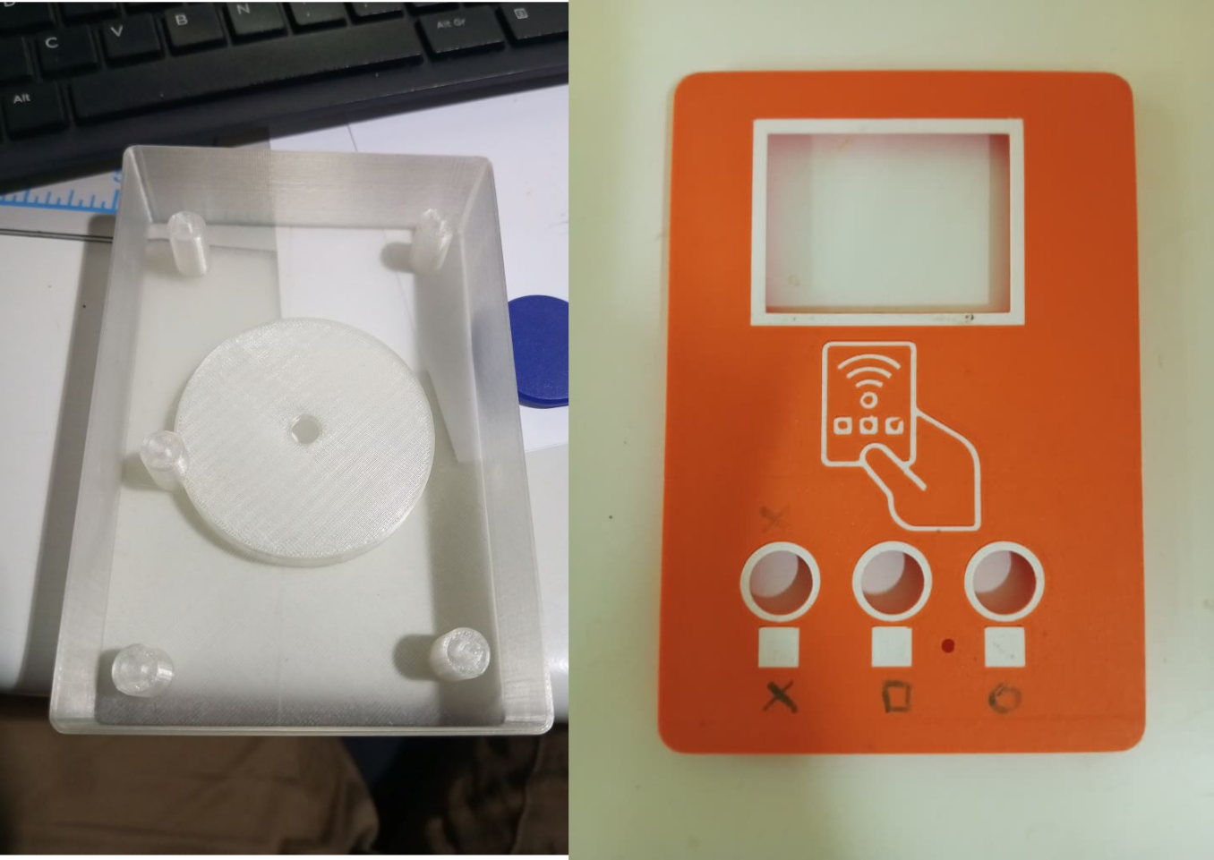
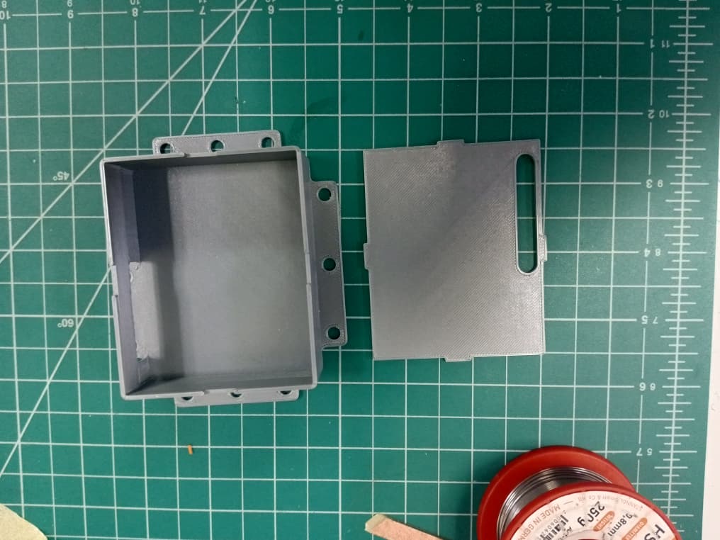
03. 3D Printing
The enclosure was printed using the Prusa MK4S+ available in our FabLab.
Printing parameters used:
| Parameter | Value |
|---|---|
| Print setting | 0.20mm QUALITY |
| Filament | PLA |
| Supports | Used on the main shell only |
| Infill | 20% |
For more details on the 3D printing procedure, refer to Week 5 — 3D Scanning and Printing.
Outdoor Access Module
Indoor Door Control Module
04. Laser Cutting
For the cover of the enclosure, I also explored a laser-cut version using 3mm MDF on the Epilog Laser available in our FabLab.
For more details on the laser cutting procedure, refer to Week 3 — Computer Controlled Cutting.
Design file:
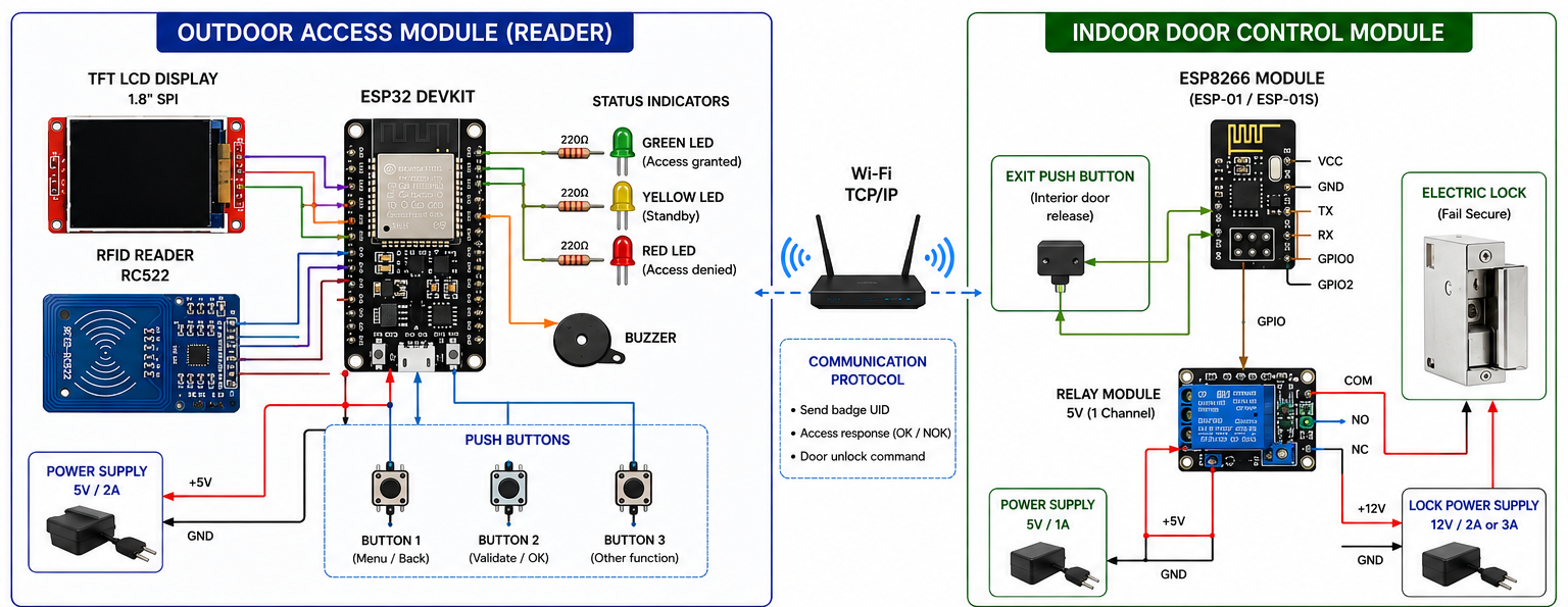
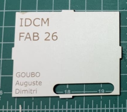
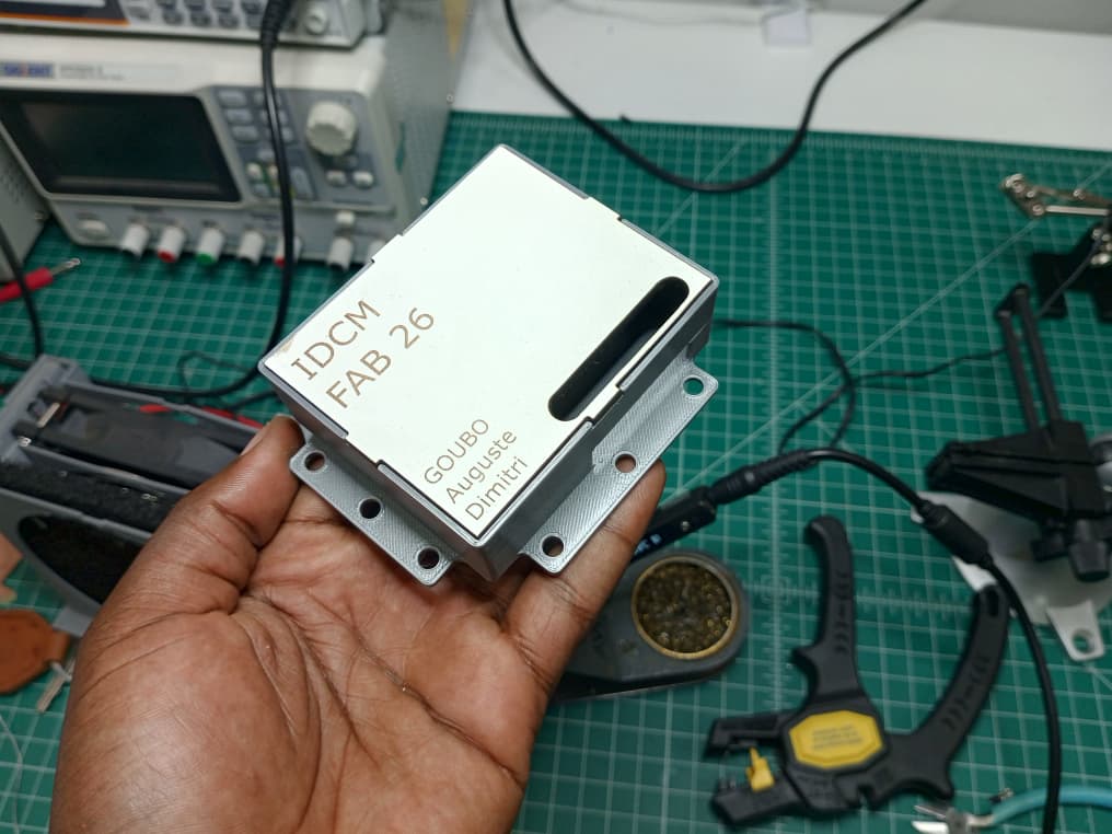
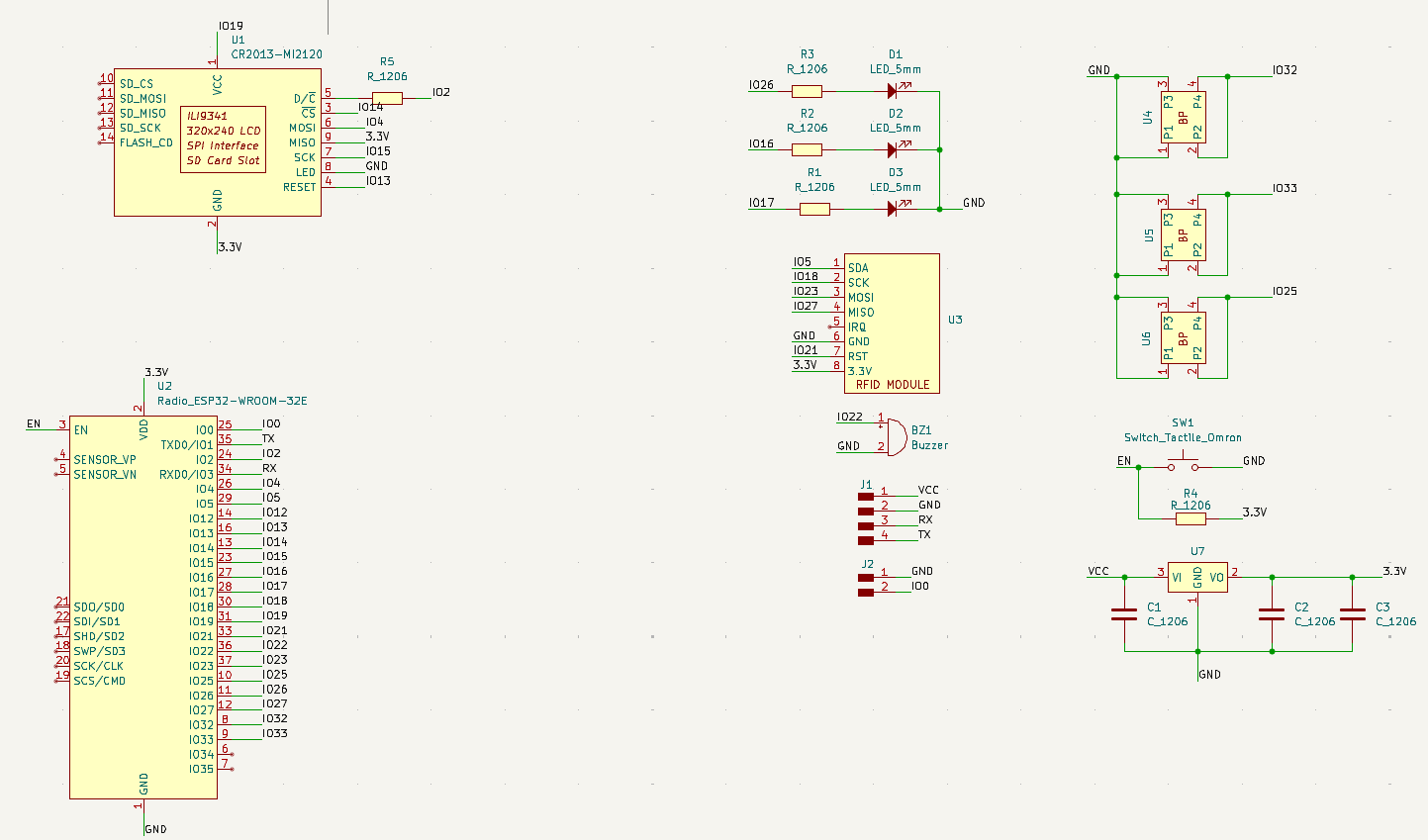
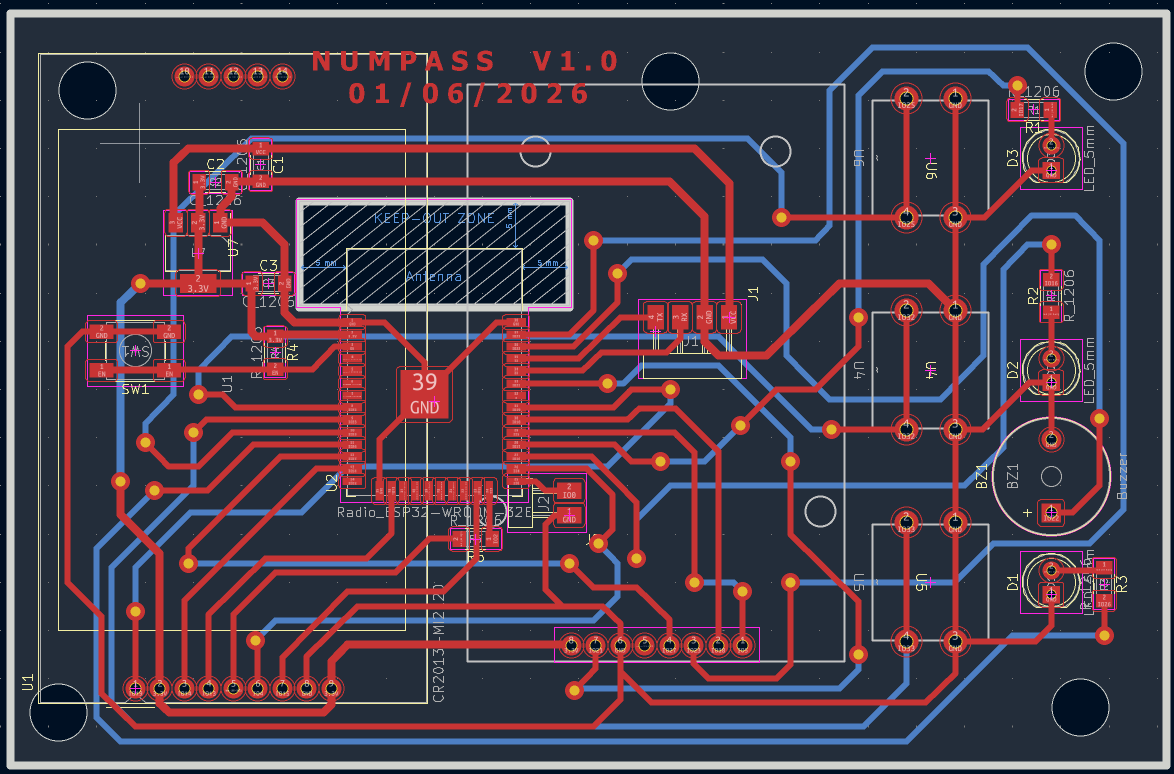
05. Electronics Design
For the electronic design of the system, I used KiCad.
Outdoor Access Module
The circuit integrates the following components on a single custom PCB:
- ESP32 microcontroller
- RFID RC522 reader (SPI communication)
- TFT LCD ILI9488 screen
- Buzzer and LED indicators
- Push button
For more details on the electronics design process, refer to Week 6 — Electronics Design.
Below is the schematic and PCB layout of the circuit:
Circuit schematic
PCB layout
PCB 3D view
Design files:
Indoor Door Control Module
The diagram below shows how all five components of the interior door control module are connected together:
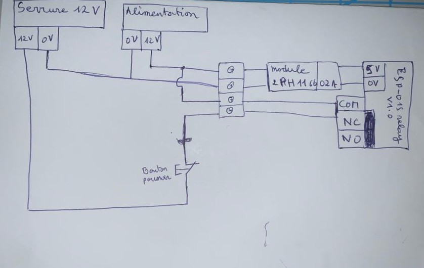
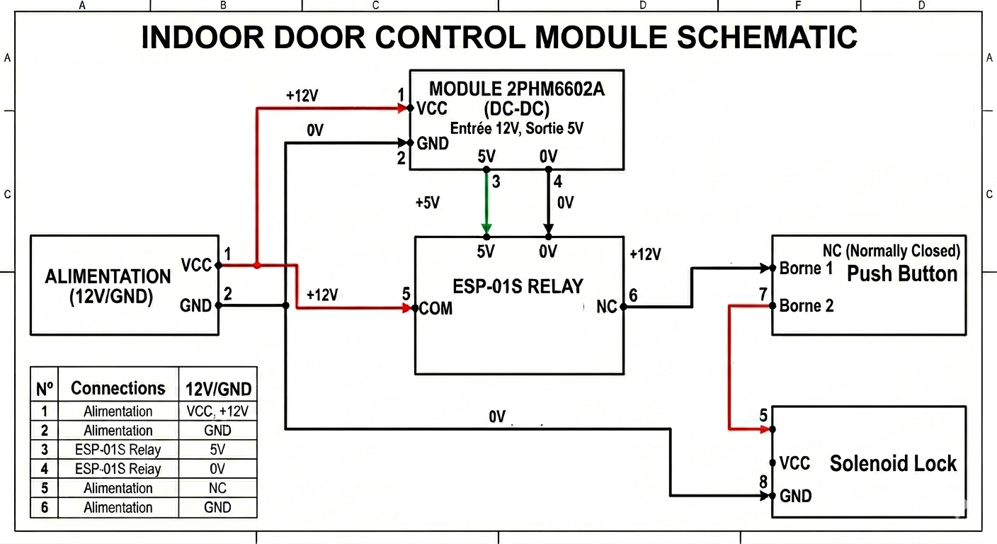
Wire Summary
| # | From | Pin | To | Pin | Wire color | Voltage |
|---|---|---|---|---|---|---|
| 1 | Power Supply | VCC | Module 2PHM6602A | VCC | Red | +12V |
| 2 | Power Supply | GND | Module 2PHM6602A | GND | Black | 0V |
| 3 | Module 2PHM6602A | 5V | ESP-01S Relay | 5V | Green | +5V |
| 4 | Module 2PHM6602A | 0V | ESP-01S Relay | 0V | Black | 0V |
| 5 | Power Supply | VCC | ESP-01S Relay | COM | Red | +12V |
| 6 | ESP-01S Relay | NC | Push Button (NC) | Terminal 1 | Black | +12V switched |
| 7 | Push Button (NC) | Terminal 2 | 12V Door Lock | VCC | Red | +12V switched |
| 8 | Power Supply | GND | 12V Door Lock | GND | Black | 0V |
1. ESP-01S Relay Module V1.0
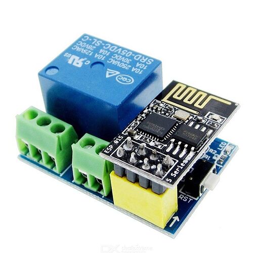
The ESP-01S Relay Module V1.0 is a compact Wi-Fi controlled relay board built around the AI-Thinker ESP-01S (ESP8266-based) Wi-Fi module. It integrates the ESP-01S directly onto the board via an 8-pin female header, making it a self-contained smart switch solution. The relay is controlled via GPIO0 of the ESP8266.
This module was chosen because it combines Wi-Fi connectivity and relay switching in a single compact form factor, which is ideal for remotely controlling the door lock in our access control system.
Key Specifications:
| Parameter | Value |
|---|---|
| Operating Voltage | DC 5V |
| Wi-Fi Module | ESP-01S (ESP8266) |
| Relay Type | Mechanical (Songle SRD-05VDC-SL-C) |
| Relay Load Capacity | 10A / 250VAC — 10A / 30VDC |
| Control Pin | GPIO0 (active LOW) |
| Voltage Regulator | AMS1117 3.3V (for ESP-01S) |
| Dimensions | 36 × 25 × 16 mm |
Wiring:
| Pin | Description |
|---|---|
| VCC | +5V DC power input |
| GND | Ground |
| NO | Normally Open relay contact |
| COM | Common relay contact |
| NC | Normally Closed relay contact |
🔗 Product page 🔗 GitHub — ESP-01S Relay V1.0 schematic and demo code
2. Mini MP1584 DC-DC Step-Down Buck Converter
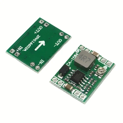
The Mini MP1584 is a small-form-factor adjustable step-down (buck) DC-DC converter module based on the MP1584 high-frequency switching regulator IC. The output voltage is adjusted via an onboard potentiometer — rotating clockwise increases the output voltage, and counter-clockwise decreases it.
In this project, the MP1584 is used to step down the 12V power supply to 5V for the ESP-01S Relay Module.
Key Specifications:
| Parameter | Value |
|---|---|
| Input Voltage | 4.5V – 28V DC |
| Output Voltage | 0.8V – 20V DC (adjustable) |
| Maximum Output Current | 3A |
| Module Size | Small form factor (approx. 22 × 17 mm) |
Pin Configuration:
| Pin | Description |
|---|---|
| IN+ | Positive input voltage terminal |
| IN− | Negative input voltage terminal |
| OUT+ | Positive output voltage terminal |
| OUT− | Negative output voltage terminal |
🔗 Component page — Components101 🔗 MP1584 Datasheet
3. 12V Electric Mortise Door Lock (Fail-Safe NC)

The HFeng 12V Electric Drop Bolt Mortise Lock is an electromagnetic door lock designed for access control systems. It operates in Fail-Safe (NC) mode, meaning the door is locked when power is on and unlocked when power is cut off. This ensures the door automatically opens in the event of a power failure — an important safety requirement for public-access environments like a FabLab.
It features an adjustable time delay (0, 3, or 6 seconds) before the bolt re-engages after an unlock command.
Key Specifications:
| Parameter | Value |
|---|---|
| Operating Voltage | DC 12V |
| Lock Mode | Magnetic induction (drop bolt) |
| Security Mode | Fail-Safe / NC (locked when powered) |
| Startup Current | 1.2A |
| Operating Current | 0.25A |
| Dimensions | 150 × 34 × 28 mm |
| Time Delay | Adjustable: 0 / 3 / 6 seconds |
Wiring:
| Wire Color | Function |
|---|---|
| Red | +12V DC |
| Black | GND |
| Yellow | NC (Normally Closed signal) |
| White | COM (Common) |
4. Push Button — Siemens SIRIUS ACT 3SU1150-0AB20-1CA0
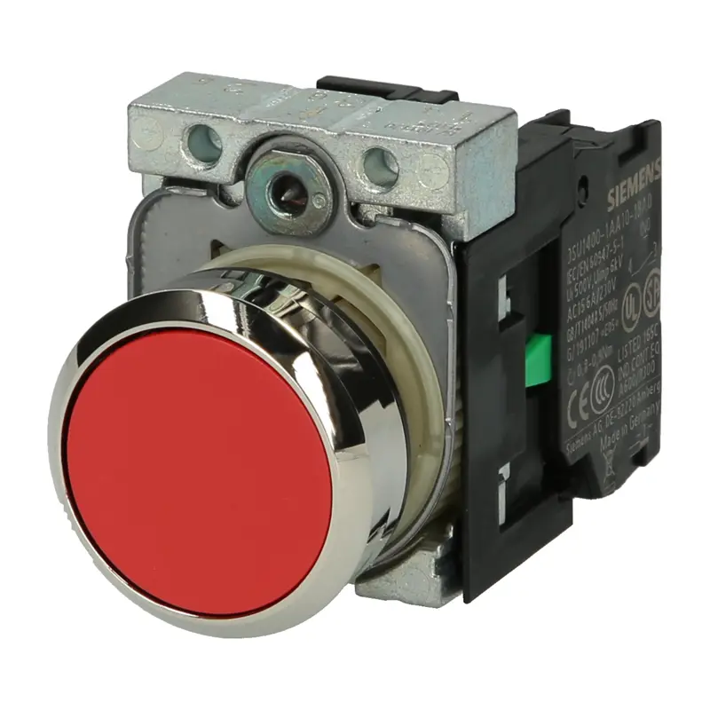
This button is used in our system as the interior manual release button, allowing someone inside the FabLab to unlock the door without needing an RFID badge.
Key Specifications:
| Parameter | Value |
|---|---|
| Series | Siemens SIRIUS ACT 3SU1 |
| Reference | 3SU1150-0AB20-1CA0 |
| Mounting Diameter | 22.3 mm |
| Contact Configuration | 1 × NC (Normally Closed) |
| Connection | Screw terminals |
| Mounting | Panel mount, front mounting |
| Max. Operating Voltage | 500V AC / 500V DC |
5. 12V 5A DC Power Supply (60W)
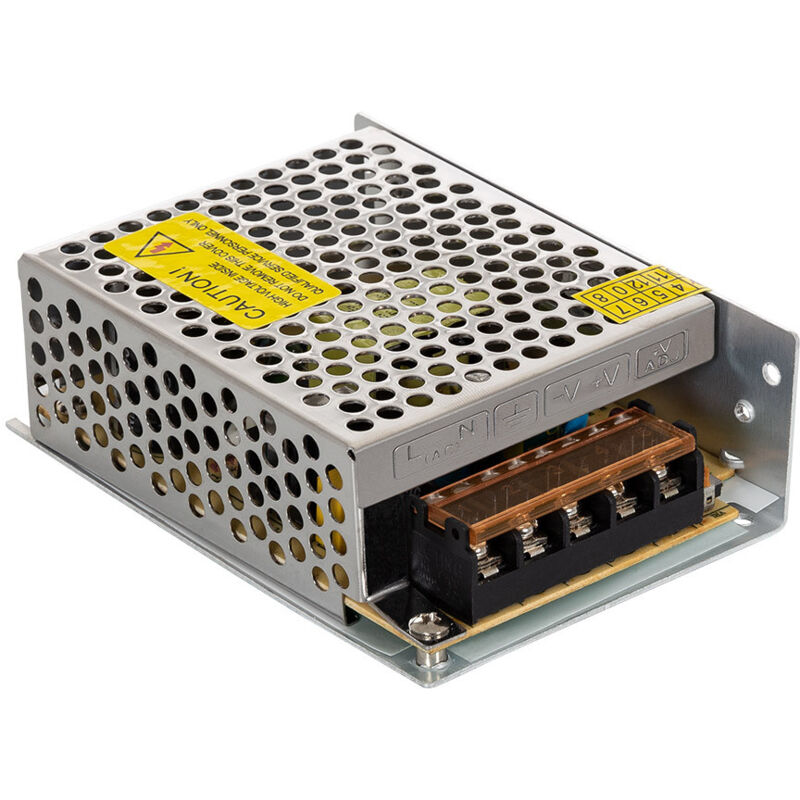
The 12V 5A DC Power Supply is an AC-to-DC switching power adapter that provides the main power for the entire interior door control module. It converts 110–240V AC mains power to a stable 12V DC / 5A output, delivering up to 60W of continuous power.
The 12V output powers the electric door lock directly, while the MP1584 buck converter steps it down to 5V for the ESP-01S relay module. This single power supply is therefore sufficient to power the entire door control sub-system.
Key Specifications:
| Parameter | Value |
|---|---|
| Input Voltage | AC 100–240V, 50/60Hz |
| Output Voltage | DC 12V |
| Output Current | 5A max |
| Output Power | 60W |
| Enclosure | Aluminium |
| Certifications | CE, RoHS |
| Adjustable Output | Yes — trimmer to adjust between ~10V and 15V |
06. Electronics Production
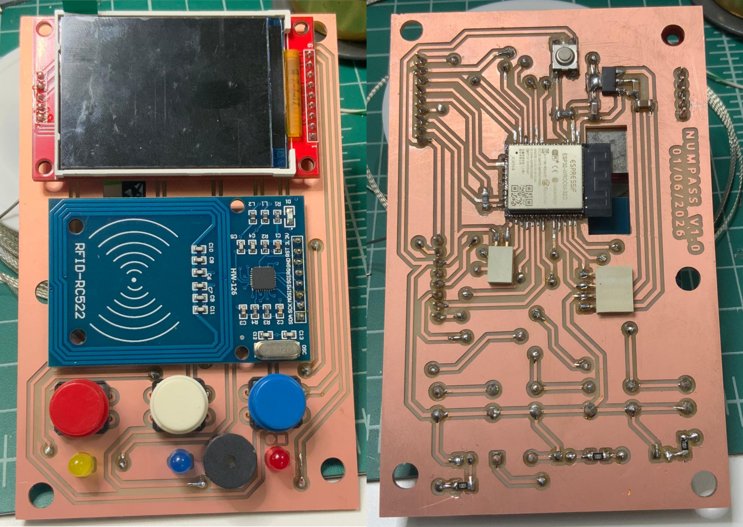
Outdoor Access Module
The PCB was fabricated using the Roland SRM-20 milling machine in our FabLab.
Tools used:
| Tool | Use |
|---|---|
| 1/64 inch flat end mill | Milling the circuit traces |
| 1/32 inch flat end mill | Cutting the board outline |
For the full milling and soldering procedure, refer to Week 8 — Electronics Production.
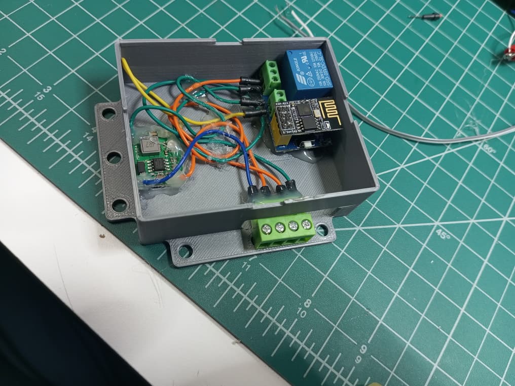
Indoor Door Control Module
07. Programming and Network Configuration
For programming and network configuration of the modules, please refer to Week 11 — Networking and Communications.
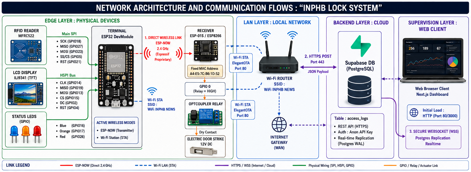
Overall Network Architecture
The system is built around 4 main layers: Physical Edge Devices, Local Area Network (LAN), Cloud Database (Backend), and Web Supervision (Client).
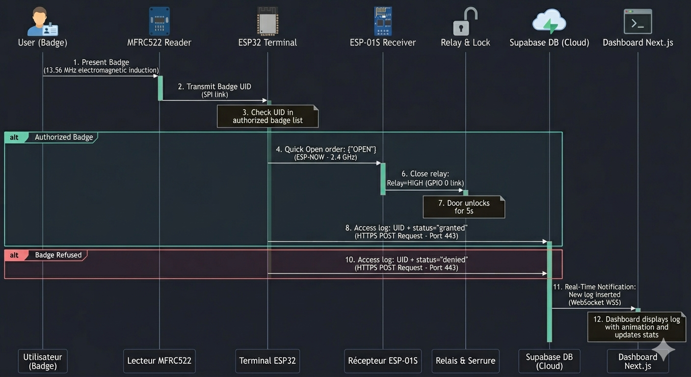
Communication Flow Timeline (Sequence Diagram)
The diagram below shows the complete path of a data frame, from the physical detection of the RFID badge to its real-time update on the web supervisor screen:
Communication Protocol Details
| Link | Protocol | Physical Layer |
|---|---|---|
| ESP32 → ESP-01S | ESP-NOW | Wi-Fi 2.4 GHz Direct (peer-to-peer) |
| ESP32 → Supabase | HTTPS (REST) | Wi-Fi Station → Internet WAN |
| Web → Supabase | WebSockets (WSS) | LAN/WAN TCP Network |
| OTA (firmware updates) | ElegantOTA (HTTP) | Local LAN Network (Port 80) |
08. Interface Programming
We chose to develop a web application using Next.js, which connects to a Supabase database to retrieve the access logs sent by the ESP32.
Setting Up the Supabase Database
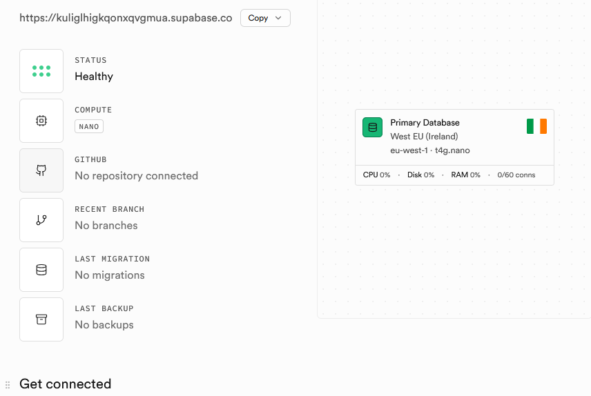
Step 1 — Create the Supabase Account and Project
-
Go to supabase.com and click Start your project.
-
Sign in with GitHub (recommended) or create an email account.
-
Click New project. Give it a name, e.g.
rfid-access. Choose the closest region. -
Generate a strong password for the database (click Generate) and save it somewhere safe — you will not be able to see it again.
-
Click Create new project and wait approximately 2 minutes for the project to be provisioned.
Retrieve Your API Keys
-
In the left menu, click Project Settings (gear icon), then API.
-
Note these two values — you will need them in the Arduino code:
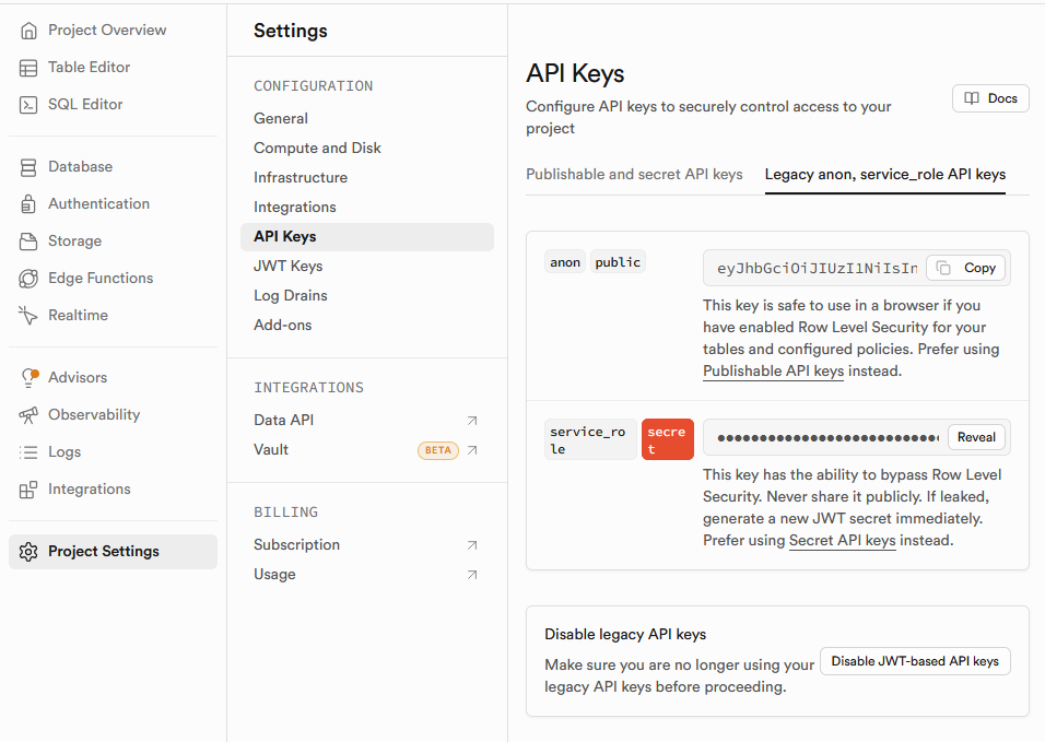
⚠️ Important: Never share the
service_rolekey — it grants full access to the database. Only use theanonkey on the ESP32.
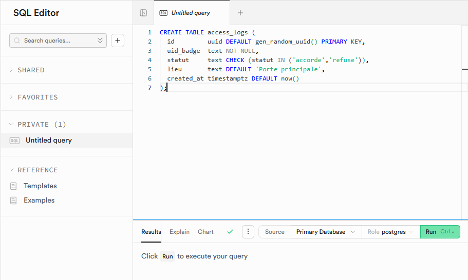
Step 2 — Create the Database Table
-
In the left menu, click SQL Editor, then New query.
-
Paste the following SQL and click Run (or
Ctrl+Enter):
CREATE TABLE access_logs (
  id         uuid DEFAULT gen_random_uuid() PRIMARY KEY,
  uid_badge  text NOT NULL,
  statut     text CHECK (statut IN ('accorde','refuse')),
  lieu       text DEFAULT 'Porte principale',
  created_at timestamptz DEFAULT now()
);
- Enable Row Level Security and allow write access from the ESP32 (anon key):
ALTER TABLE access_logs ENABLE ROW LEVEL SECURITY;

CREATE POLICY "insert_depuis_esp32"
ON access_logs FOR INSERT
TO anon
WITH CHECK (true);

CREATE POLICY "lecture_admin"
ON access_logs FOR SELECT
TO anon
USING (true);
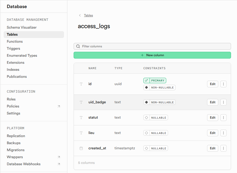
✅ In the Table Editor, you should now see the
access_logstable with its 5 columns.
Web Application Programming
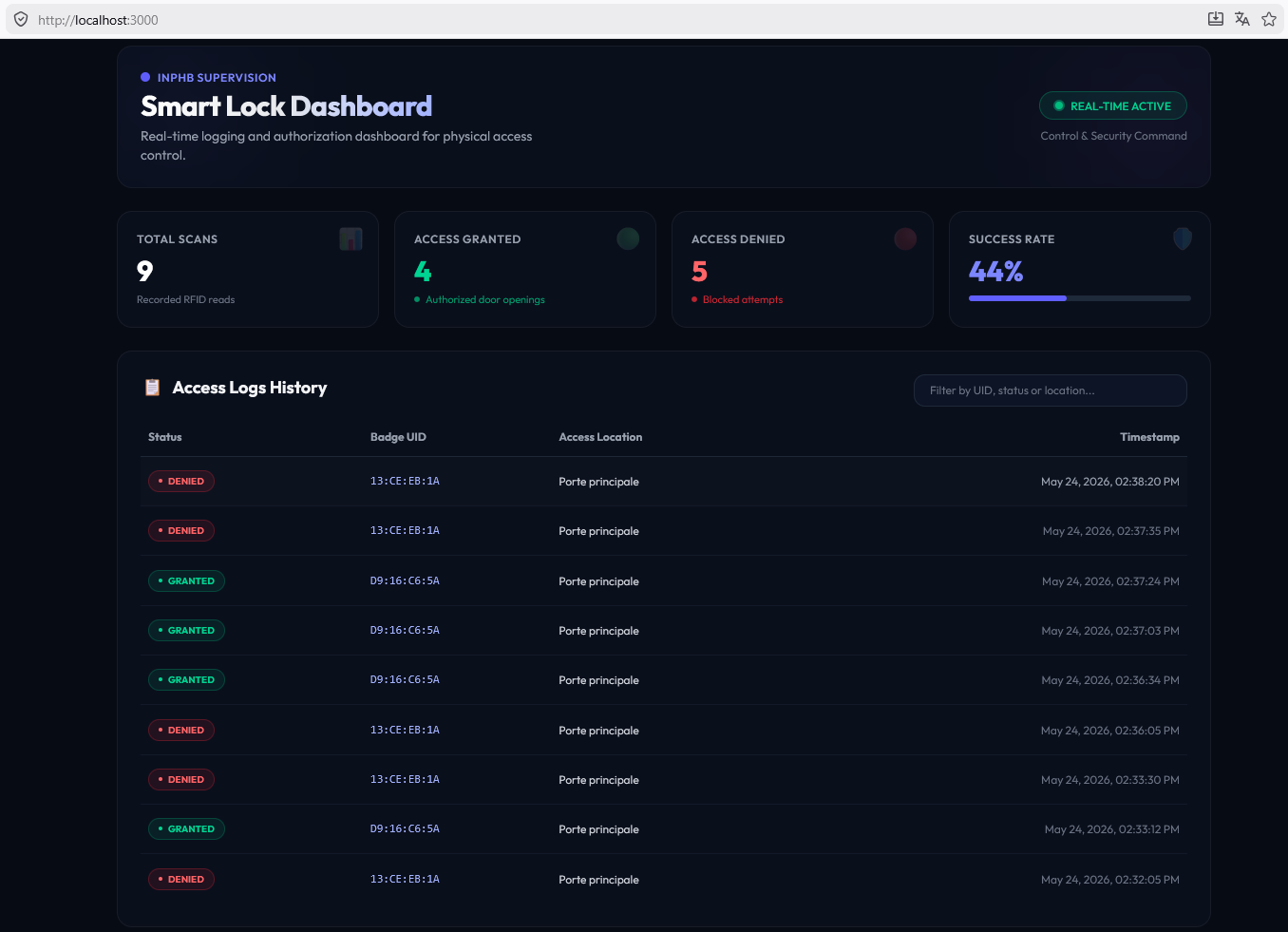
The web application was built with Next.js.
Here is the result:
1. Installing the Required Tools
To run this web application (Next.js + React) locally on your computer, you need to install Node.js.
Node.js is the JavaScript runtime that runs the Next.js server locally. NPM is the package manager that installs dependencies such as the Supabase client.
- Go to the official Node.js website: https://nodejs.org/
- Download the LTS version.
- Run the downloaded
.msiinstaller and follow the setup wizard (leave all default options checked).
2. Configuring the Web Application
Open the file app-web/.env.local and replace the placeholder values with your actual Supabase credentials:
# Your project URL (available in Supabase → Settings → API)
NEXT_PUBLIC_SUPABASE_URL=https://your-project-id.supabase.co

# Your public anonymous key (anon public, available in Supabase → Settings → API)
NEXT_PUBLIC_SUPABASE_ANON_KEY=your-anon-public-key
3. Running and Testing Locally
Once your tools are installed and Supabase is configured, you can run the application locally and simulate badge scans to validate the full system.
Step 1 — Install NPM dependencies
Open a terminal, navigate to the application folder, and install the required modules (Next.js, Supabase):
Step 2 — Start the development server
Run the following command to start the application locally:
The terminal will confirm that the server is running at: http://localhost:3000
Step 3 — Open the application
Open your browser and go to http://localhost:3000.
Source files:
09. Firmware — System Programming
Program 1 — Main Controller (ESP32)
Overview
The ESP32 is the brain of the system. It runs the following tasks simultaneously:
- Reads RFID badges via the RC522 reader (SPI bus)
- Displays real-time system logs on an ILI9341 TFT screen (HSPI bus)
- Controls three status LEDs (red, blue, orange)
- Connects to Wi-Fi and logs access events to a Supabase database via HTTPS
- Sends wireless commands to the ESP-01S relay module via ESP-NOW
- Exposes an OTA (Over-The-Air) firmware update endpoint via ElegantOTA
Libraries Used
| Library | Role |
|---|---|
WiFi.h |
Wi-Fi connection management |
esp_now.h |
ESP-NOW peer-to-peer wireless protocol |
SPI.h |
SPI bus communication |
MFRC522.h |
RFID RC522 reader driver |
Adafruit_GFX.h |
Graphics primitives for the TFT screen |
Adafruit_ILI9341.h |
ILI9341 TFT display driver |
ESPAsyncWebServer.h |
Asynchronous HTTP web server |
AsyncTCP.h |
Asynchronous TCP support for ESP32 |
ElegantOTA.h |
Web-based OTA firmware update interface |
HTTPClient.h |
HTTP client for Supabase POST requests |
WiFiClientSecure.h |
HTTPS (TLS) client for secure connections |
Pin Configuration
RFID RC522 — Main SPI bus (custom GPIO reassignment)
| Signal | GPIO |
|---|---|
| SS (Chip Select) | 5 |
| RST | 21 |
| SCK | 18 |
| MISO | 27 |
| MOSI | 23 |
ILI9341 TFT Screen — HSPI bus (dedicated secondary SPI)
| Signal | GPIO |
|---|---|
| CS | 15 |
| DC | 2 |
| RST | 4 |
| CLK | 14 |
| MOSI | 13 |
| MISO | 19 |
LEDs
| LED | GPIO |
|---|---|
| Red (access denied) | 26 |
| Blue (standby / ready) | 16 |
| Orange (processing) | 17 |
Note: The RFID and TFT screen use two separate SPI buses to avoid conflicts. The RFID uses the main
SPIobject with custom GPIO pins, while the TFT uses theSPIClass spiTFT(HSPI)object on the dedicated HSPI hardware bus.
Authorized Badges
Authorized RFID badge UIDs are stored directly in flash memory as byte arrays:
const byte NB_BADGES = 2;
byte badges_autorises[NB_BADGES][4] = {
  {0xD9, 0x16, 0xC6, 0x5A},
  {0xAB, 0xCD, 0xEF, 0x01}
};
To add a new badge, simply add its 4-byte UID to this array and increment NB_BADGES.
The UID of any badge can be read by scanning it and observing the [RFID] log line on
the TFT screen or the Serial monitor.
ESP-NOW Communication
ESP-NOW is used to send a wireless command from the ESP32 to the ESP-01S relay module without going through a router. The two devices communicate directly, peer-to-peer.
The message structure is defined as:
When an authorized badge is detected, the ESP32 sends:
The MAC address of the ESP-01S must be entered manually in the macESP01 array.
This address is printed to the Serial monitor when Program 2 boots.
Supabase Cloud Logging
Every badge scan — whether authorized or denied — is logged to a Supabase PostgreSQL
database via an HTTPS POST request. The function sendLogToSupabase() builds a JSON
payload and sends it to the REST API endpoint:
String jsonPayload = "{\"uid_badge\":\"" + uid + "\",\"statut\":\"" + statut + "\"}";
http.POST(jsonPayload);
The statut field is either "accorde" (granted) or "refuse" (denied).
WiFiClientSecureis used withclient.setInsecure()to bypass strict certificate verification — acceptable for a prototype.
TFT Screen Display
The screen is divided into two zones:
- Header (top 52px): Shows the system title, MAC address, and IP address. Updated once after Wi-Fi connects.
- Log area (below 60px): Scrolling list of up to 10 log lines. Each new log line is color-coded:
- 🟢 Green — authorized access, successful operations
- 🔴 Red — denied access, errors
- 🟠 Orange — in-progress operations (OTA, Supabase sending)
- ⬜ White — general system messages
When a badge is scanned, a colored flash bar appears between the header and the log area for 600ms as an immediate visual indicator.
OTA Updates
The firmware can be updated wirelessly via the ElegantOTA web interface, accessible at:
Setup Sequence
1. Initialize LEDs → orange (starting)
2. Initialize TFT screen → display "Demarrage..."
3. Initialize RFID reader
4. Connect to Wi-Fi
5. Draw header with IP and MAC address
6. Initialize ESP-NOW → register peer (ESP-01S MAC)
7. Start OTA web server
8. Set LED → blue (ready)
9. Display "Attente badge..."
Main Loop Logic
Loop:
├── ElegantOTA.loop()          ← handles OTA requests
└── RFID scan check
    ├── No card present → skip
    └── Card detected:
        ├── Read UID → format as hex string (e.g. "D9:16:C6:5A")
        ├── Log UID to screen
        ├── Check against authorized list
        │   ├── AUTHORIZED:
        │   │   ├── Log "Acces autorise" (green)
        │   │   ├── Flash green bar on screen
        │   │   ├── LED → orange
        │   │   ├── Send "OPEN" via ESP-NOW to ESP-01S
        │   │   ├── Wait 500ms
        │   │   ├── LED → blue
        │   │   └── Log to Supabase (statut: "accorde")
        │   └── DENIED:
        │       ├── Log "Acces refuse" (red)
        │       ├── Flash red bar on screen
        │       ├── LED → red
        │       ├── Wait 2000ms
        │       ├── LED → blue
        │       └── Log to Supabase (statut: "refuse")
        ├── Log "Attente badge..."
        ├── rfid.PICC_HaltA()         ← stop communication with card
        ├── rfid.PCD_StopCrypto1()    ← reset RFID crypto
        └── delay(1000)               ← debounce
Complete Code — Program 1
| main_controller_esp32.ino | |
|---|---|
1 2 3 4 5 6 7 8 9 10 11 12 13 14 15 16 17 18 19 20 21 22 23 24 25 26 27 28 29 30 31 32 33 34 35 36 37 38 39 40 41 42 43 44 45 46 47 48 49 50 51 52 53 54 55 56 57 58 59 60 61 62 63 64 65 66 67 68 69 70 71 72 73 74 75 76 77 78 79 80 81 82 83 84 85 86 87 88 89 90 91 92 93 94 95 96 97 98 99 100 101 102 103 104 105 106 107 108 109 110 111 112 113 114 115 116 117 118 119 120 121 122 123 124 125 126 127 128 129 130 131 132 133 134 135 136 137 138 139 140 141 142 143 144 145 146 147 148 149 150 151 152 153 154 155 156 157 158 159 160 161 162 163 164 165 166 167 168 169 170 171 172 173 174 175 176 177 178 179 180 181 182 183 184 185 186 187 188 189 190 191 192 193 194 195 196 197 198 199 200 201 202 203 204 205 206 207 208 209 210 211 212 213 214 215 216 217 218 219 220 221 222 223 224 225 226 227 228 229 230 231 232 233 234 235 236 237 238 239 240 241 242 243 244 245 246 247 248 249 250 251 252 253 254 255 256 257 258 259 260 261 | |
Program 2 — Door Controller (ESP-01S Relay Module)
Overview
The ESP-01S Relay Module acts as a wireless slave in the system. It connects to the same Wi-Fi network as the ESP32 and listens for ESP-NOW messages. When it receives an "OPEN" command, it activates the relay for 5 seconds, unlocking the electric door lock, then deactivates it automatically.
It also exposes an OTA update endpoint so its firmware can be updated wirelessly without physical access to the module.
Libraries Used
| Library | Role |
|---|---|
ESP8266WiFi.h |
Wi-Fi connection management for ESP8266 |
ESPAsyncTCP.h |
Asynchronous TCP for ESP8266 |
ESPAsyncWebServer.h |
Asynchronous HTTP web server |
ElegantOTA.h |
Web-based OTA firmware update interface |
espnow.h |
ESP-NOW protocol for ESP8266 |
Pin Configuration
| Signal | GPIO |
|---|---|
| Relay control | GPIO0 |
Note: On the ESP-01S module, GPIO0 is used to control the onboard relay.
RELAY_ON = HIGHactivates the relay;RELAY_OFF = LOWdeactivates it. Verify the relay logic of your specific module — some relay boards are active LOW.
ESP-NOW Reception
The ESP-01S is configured as an ESP-NOW slave. It registers a receive callback onDataRecv() that is triggered every time a message arrives:
void onDataRecv(uint8_t *mac, uint8_t *data, uint8_t len) {
  memcpy(&messageRecu, data, sizeof(messageRecu));
  if (strcmp(messageRecu.commande, "OPEN") == 0) {
    digitalWrite(RELAY_PIN, RELAY_ON);
    delay(5000);        // hold open for 5 seconds
    digitalWrite(RELAY_PIN, RELAY_OFF);
  }
}
The message structure must be identical on both sides for ESP-NOW to deserialize the payload correctly:
Setup Sequence
1. Initialize relay pin → OFF (door locked at startup)
2. Connect to Wi-Fi (STA mode)
3. Print IP and MAC address to Serial monitor
4. Initialize ESP-NOW → set role as SLAVE
5. Register receive callback (onDataRecv)
6. Start OTA web server
Main Loop Logic
Loop:
└── ElegantOTA.loop()    ← handles OTA requests (non-blocking)
    (no other logic — everything is event-driven via ESP-NOW callback)
The loop is intentionally empty except for OTA handling. All door-control logic is triggered asynchronously by the ESP-NOW receive callback.
Complete Code — Program 2
10. Assembly and Final Testing
Once all modules were validated individually, I assembled the full system.