8. Electronics Production
Group Assignment
- Characterize the design rules for your in-house PCB production process: document feeds, speeds, plunge rate, depth of cut (traces and outline), and tooling.
- Extra credit: send a PCB out to a board house.
- Document your work on the group work page and reflect on your individual page what you learned.
To see our group assignment, click here.
Individual Assignment
- Make and test the development board that you designed to interact and communicate with an embedded microcontroller.
- Extra credit: make it with another process.
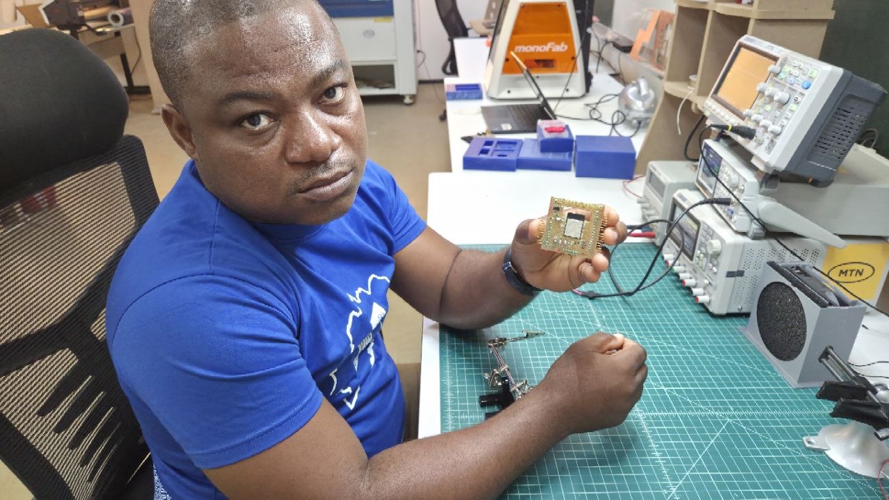
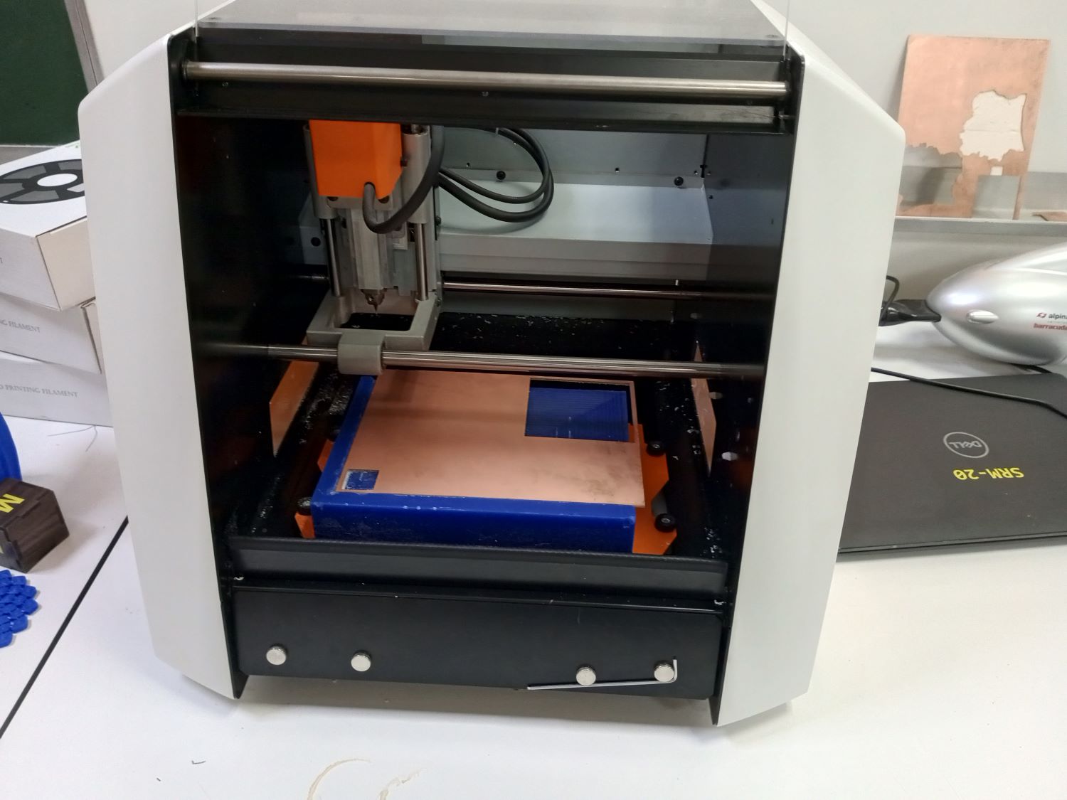
For this week's assignment — the fabrication of an electronic circuit — I used the Roland SRM-20 milling machine available in our Fab Lab. The PCB design used is the one I created during Week 6 (Electronics Design).
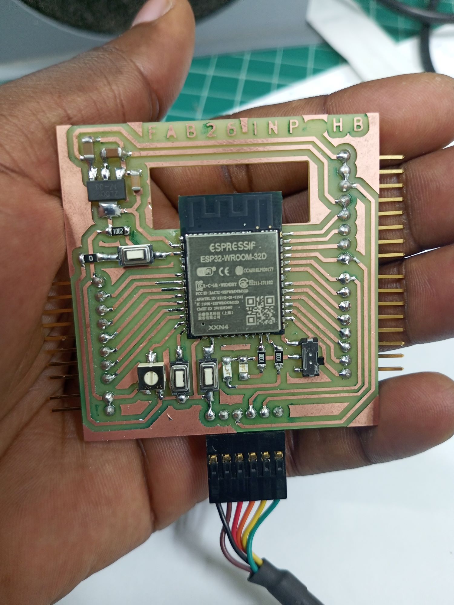
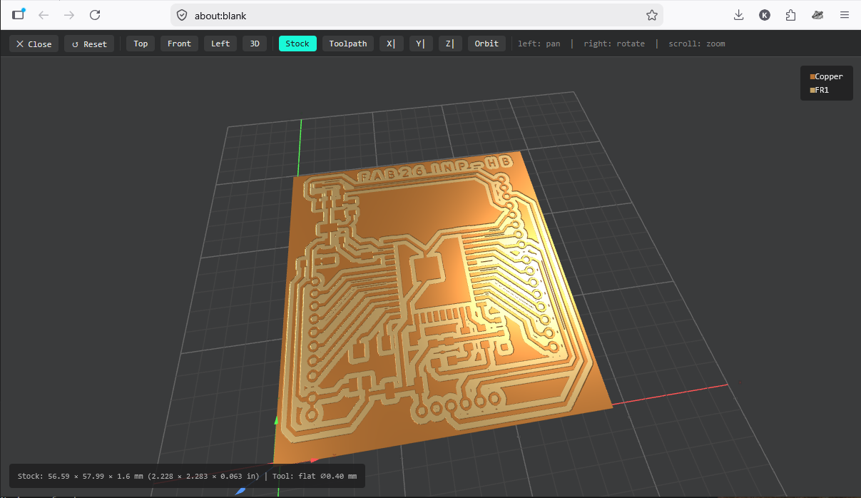
The goal at the end of this week is to obtain the following finished circuit board:
To begin the fabrication process, I first retrieved the .SVG files for both the traces and the outline of my circuit, as shown below.
Click here to download the SVG files.

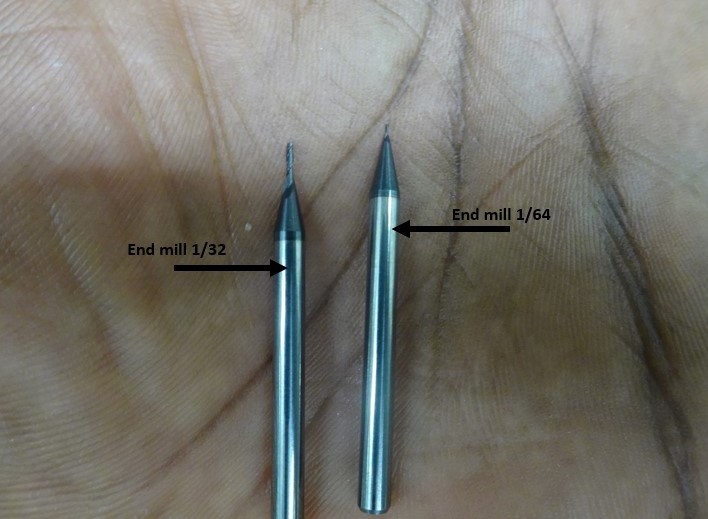
Before starting the milling, I needed to generate the toolpaths for both the traces and the board outline. Two different end mills were used:
- A 1/64 inch flat end mill for milling the circuit traces
- A 1/32 inch flat end mill for cutting the board outline
Toolpath Generation
Several software solutions exist for generating toolpaths, including Vcarve, FlatCAM, and mods CE. I chose mods CE because it is open-source and was specifically designed with Fab Lab tools in mind.
Using mods CE
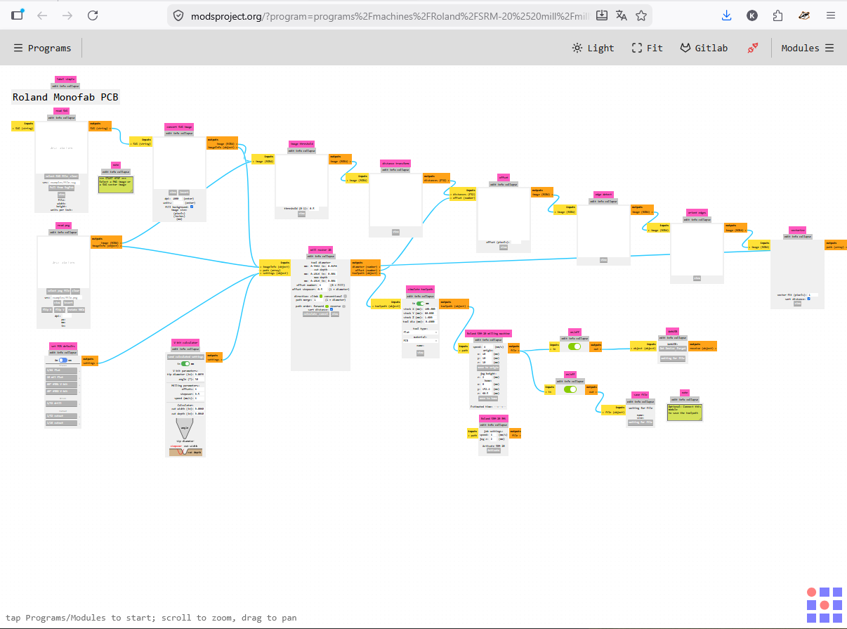
Mods CE is an online tool developed by Neil Gershenfeld's Center for Bits and Atoms at MIT. It converts image files into milling toolpath files.
For more information on mods, click here.
Steps:
-
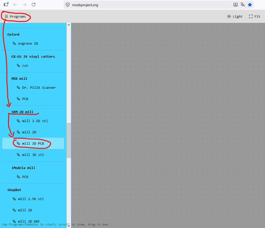
Open mods CE.
-
Click on "Program", scroll down to the SRM20-mill section, and select "mill 2D PCB".
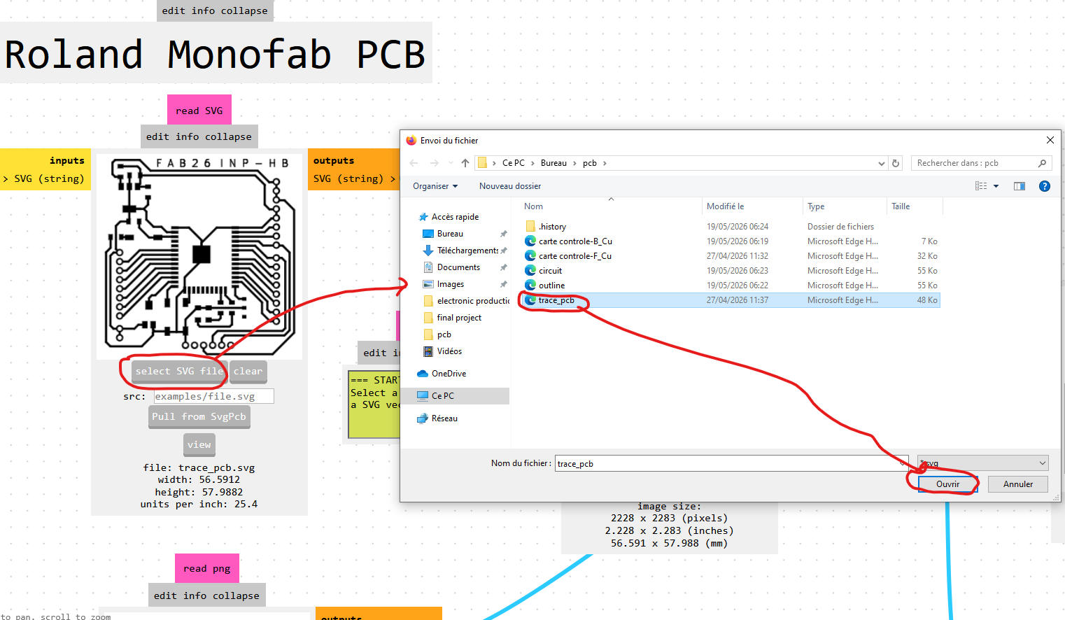
-
In the "read svg" module, click "select svg file", choose the SVG file for the circuit traces, and click "Open".
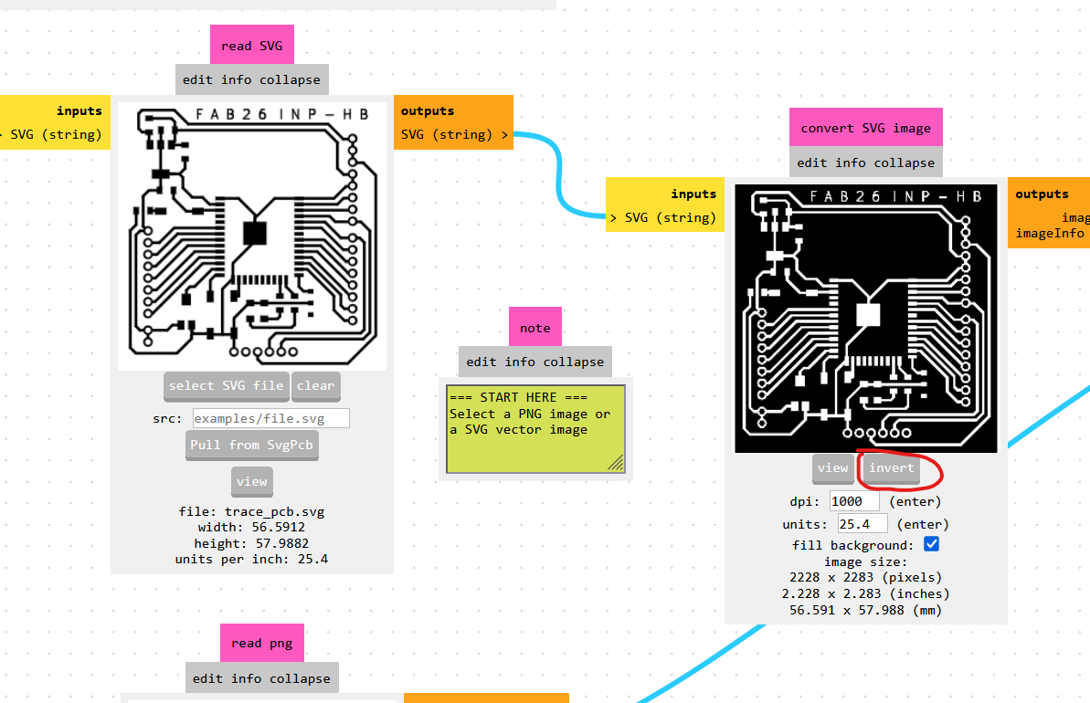
-
In the "convert SVG image" module, click "invert" to invert the image colors as shown below.
-
In the "set PCB defaults" module, click "mill traces (1/64)" to apply the correct cutting parameters for the 1/64 inch end mill.
Then, in the "Roland SRM-20 Absolute coordinates" module, set x, y, and z to 0 so the tool starts at the origin defined on the machine, and set the jog height to 12.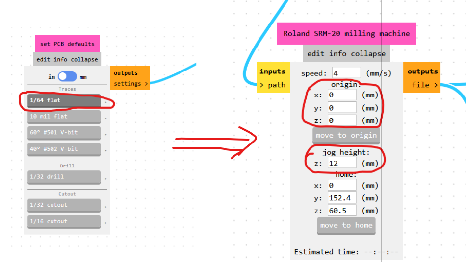
-
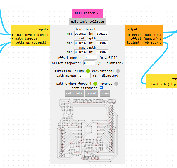
In the "mill raster 2D" module, click "calculate" to generate the G-code file.
-
Repeat the same procedure to generate the G-code for the board outline, this time using the outline SVG file and the 1/32 inch end mill settings.
Machining the Circuit Board
For the machining process, I followed the Fab Academy tutorial. The process is broken down into three steps:
Step 1: Machine Preparation
- Turn on the Roland SRM-20, connect it to the computer, and launch the VPanel software.
-
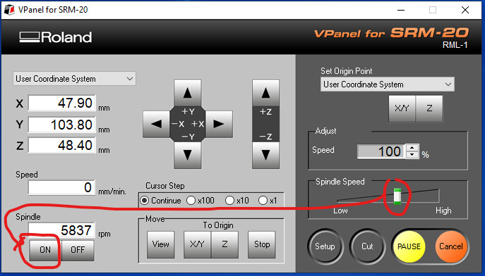
Warm up the spindle for 10 minutes at half speed before starting. To do this, move the slider in the "Spindle Speed" module to the midpoint, click "ON" in the "Spindle" section, and wait 10 minutes.
-
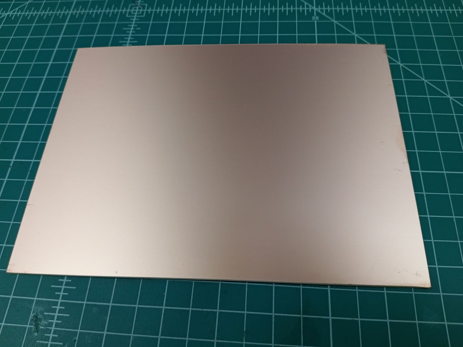
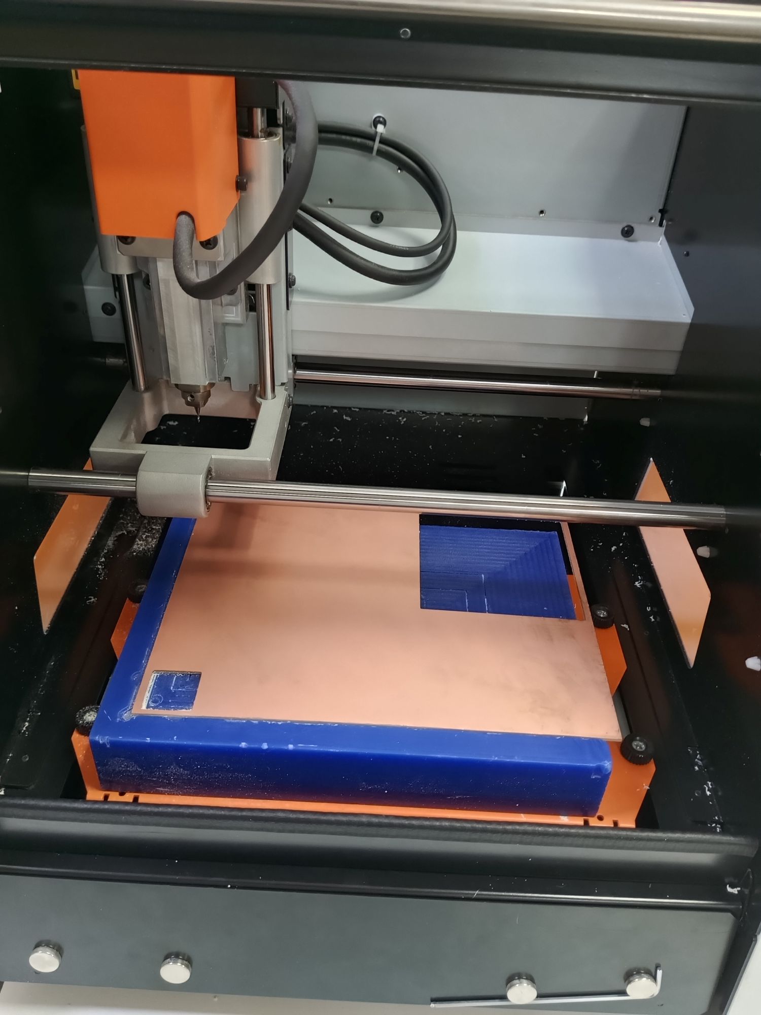
After 10 minutes, click "OFF". Then proceed to mount the copper board on the machine bed as shown below.
-
Since we begin with the traces, mount the 1/64 inch end mill.
⚠️ Warning: Make sure the tool is secured properly — if it falls, it will break.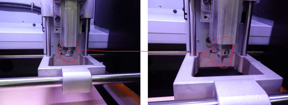
Step 2: Setting the X, Y, and Z Origin
-
Use the Y+, Y-, X+, and X- buttons in VPanel to move the tool to the desired starting position for X and Y.
Note: The (0,0) origin defined in mods is the lower-left corner of the design.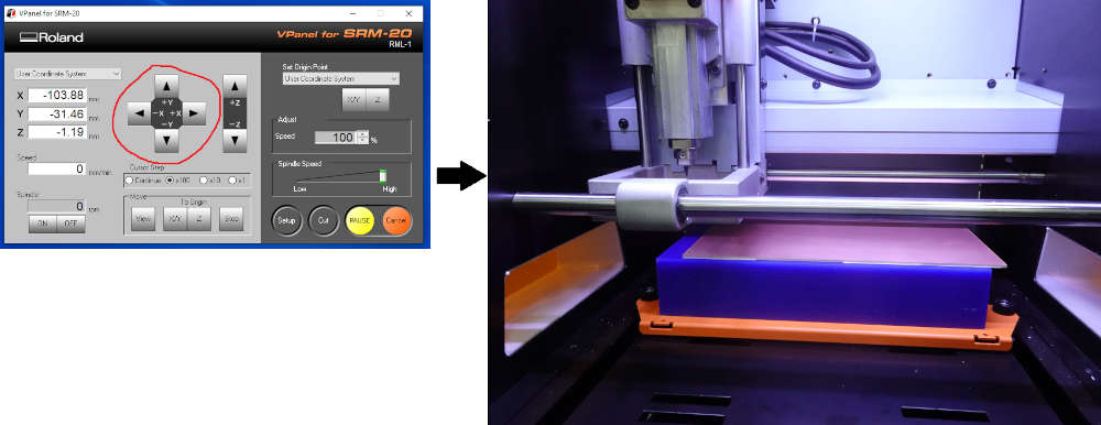
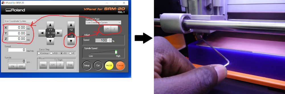
-
For the Z origin: click "Z-" to bring the tool close to the board surface. Then click the X/Y and Z buttons in the "Set Origin Point" section. Loosen the end mill collet so the bit rests on the board surface under its own weight, then re-tighten it. This sets the Z zero precisely at the board surface.
Step 3: Milling the Circuit Traces
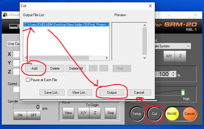
-
In VPanel, click "Cut", select the trace G-code file generated by mods, and click "Output" to start the machining.
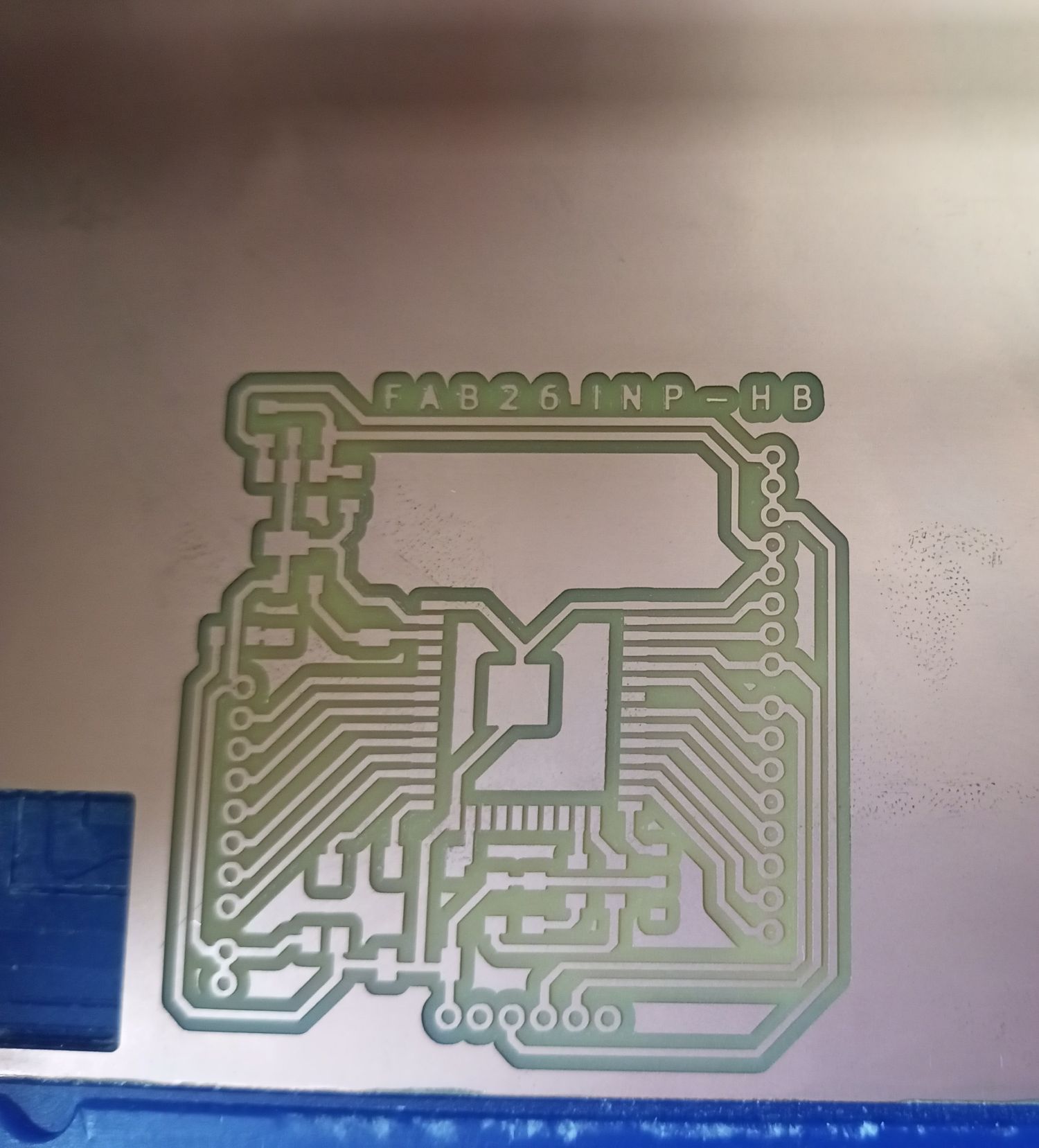
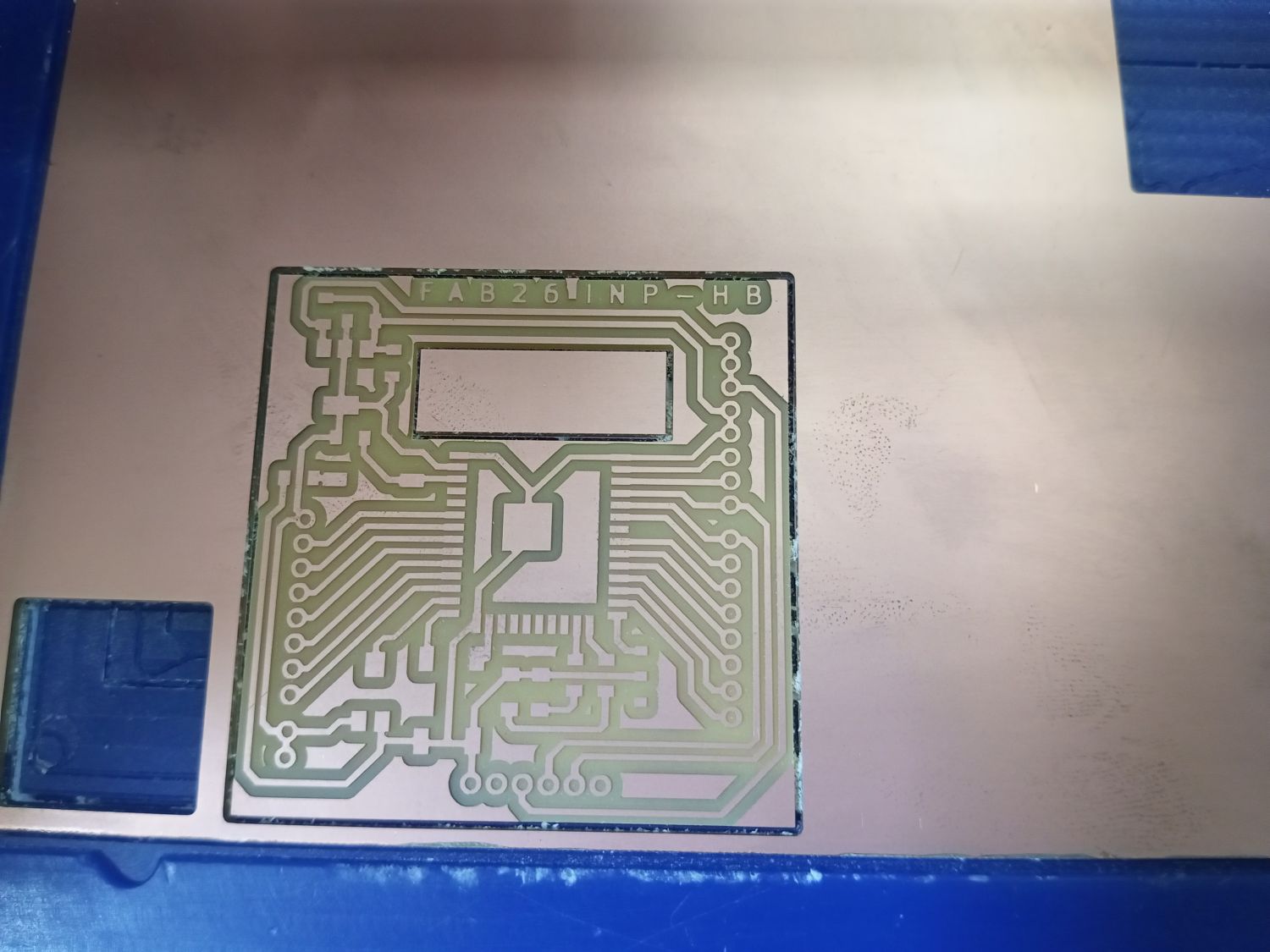
After approximately 30 minutes of milling, the traces were completed:
-
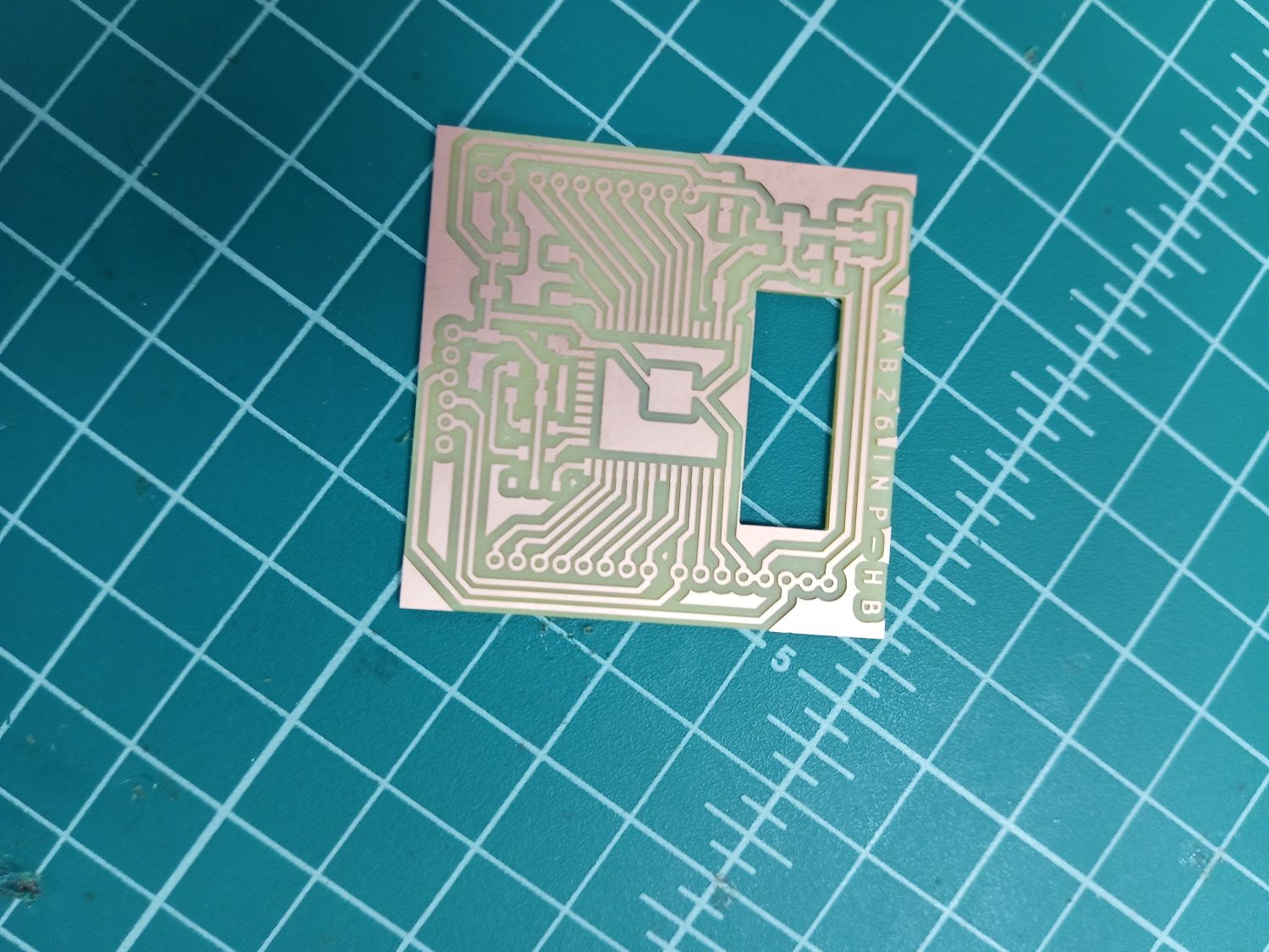
Next, I swapped to the 1/32 inch end mill for cutting the board outline. After re-zeroing the Z axis, I launched the outline cut. After approximately 4 minutes, the board was fully cut out:
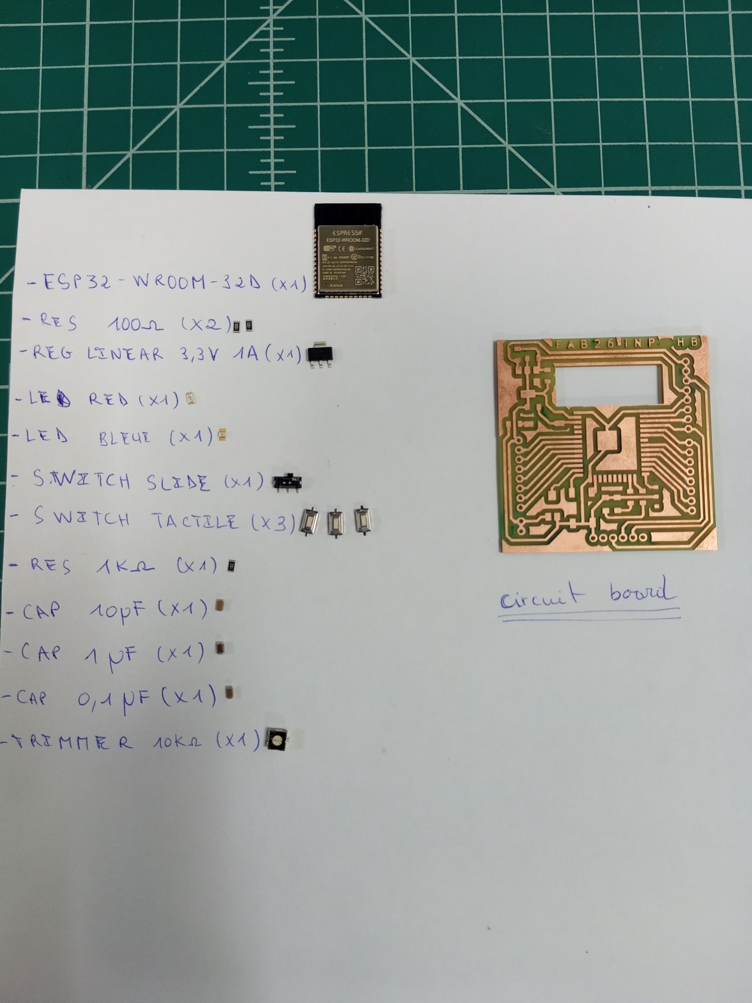
Soldering Components onto the Board
I gathered all the electronic components before starting soldering to make the process more efficient.
After 2 hours of soldering, here is the result 😊:
Testing the Circuit Board
To test the board, I programmed it using the Arduino IDE to blink the blue LED on the circuit.
| blink.ino | |
|---|---|
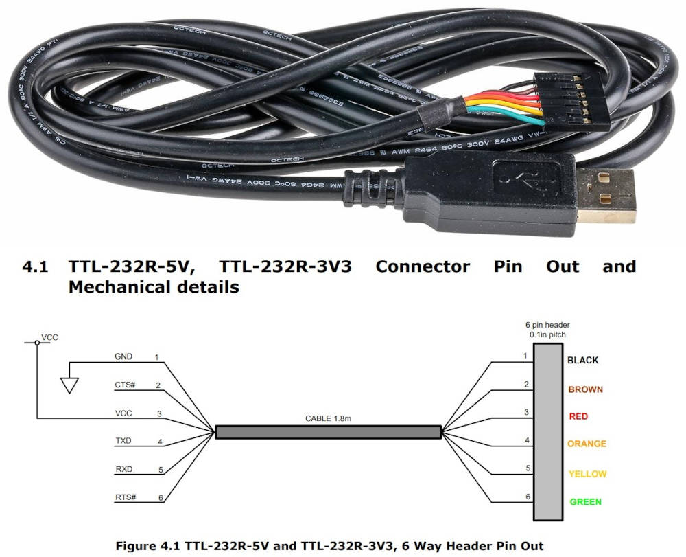
To upload the program, I used a TTL-232R-5V USB-to-UART cable. The pin connections were made following the official datasheet.
To upload code to the ESP32, the microcontroller must be placed in Boot mode. This is done by activating the switch on the board, which connects the IO0 pin of the ESP32 to GND.
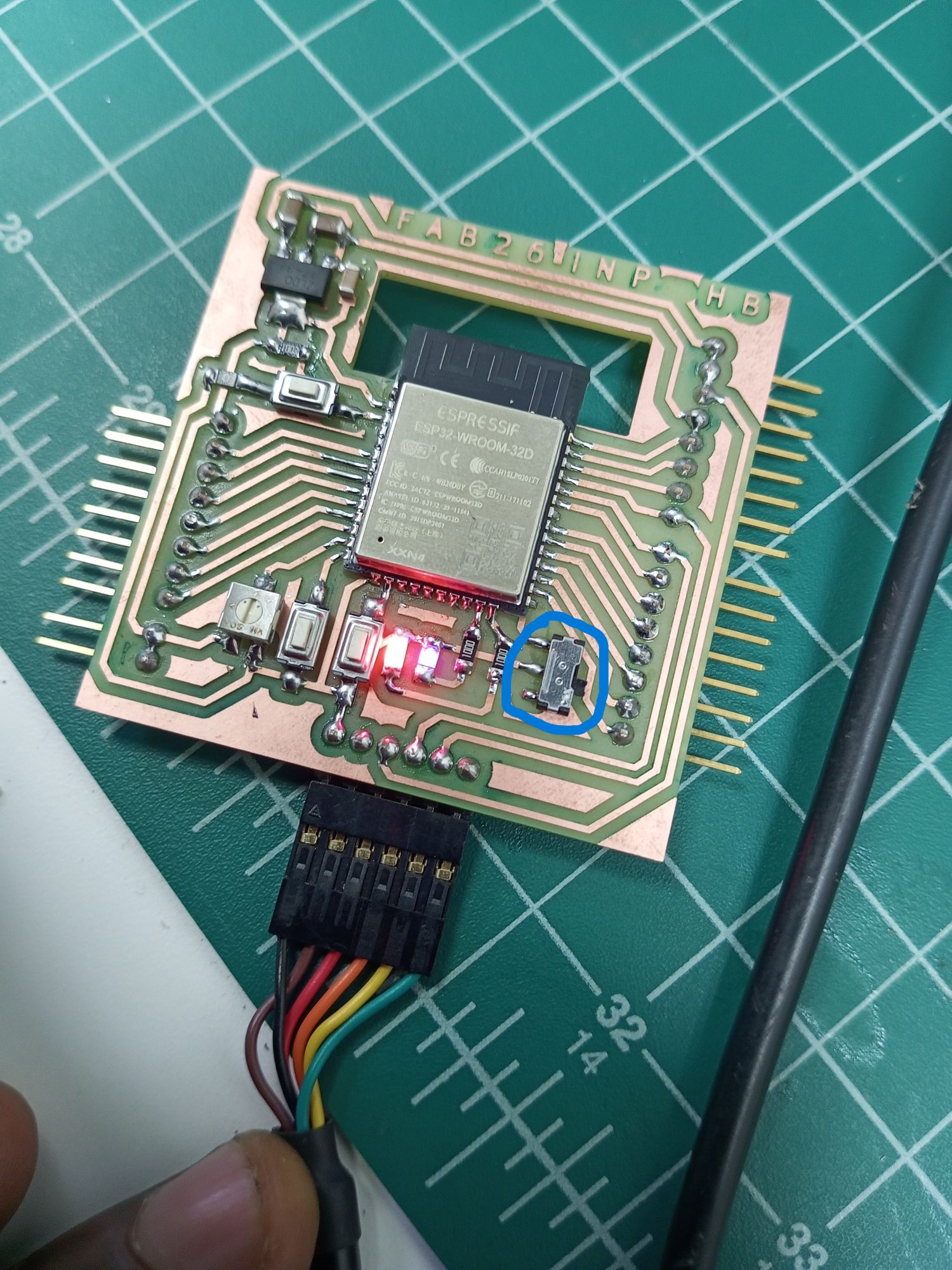
The board works correctly — the LED blinks as expected! 🎉
HERO SHOTS 😊😊😊