15. System Integration
Assignment:
Individual assignment:
- Design and document the system integration for your final project.
Your project should demonstrate how all the modules developed during the Fab Academy work together as a unified system, including:
- 2D and 3D design
- Additive and subtractive fabrication processes
- Electronics design and production
- Embedded microcontroller interfacing and programming
- System integration and packaging
Project Introduction
This week, the objective is to bring together all the components developed throughout the Fab Academy into a single, functional and integrated system.
My final project is an RFID Access Control System for the FabLab. The system is designed to solve a real problem observed at our FabLab: the physical key was frequently unavailable or lost, and there was no reliable way to track who entered the lab and at what time.
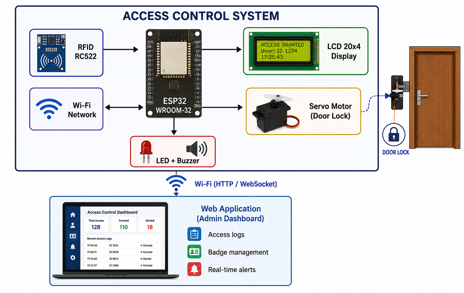
The integrated system includes:
- An RFID badge reader to identify users
- An ESP32 microcontroller as the central processing unit
- A 20x4 LCD screen to display information in real time
- A servo motor to control the door lock mechanism
- LEDs and a buzzer for visual and audio feedback
- A web-based management application for remote monitoring and administration of access logs
System Architecture
Global Architecture Diagram
The diagram below presents the overall architecture of the system, showing how all components interact with each other:
System Integration Steps
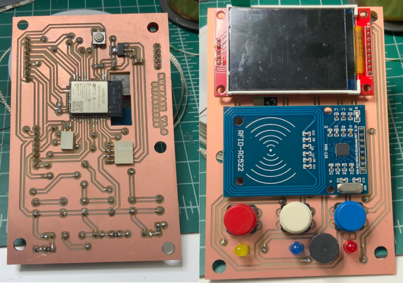
Step 1 — Electronics Integration
The custom PCB designed during Week 6 (Electronics Design) and produced during Week 8 (Electronics Production) serves as the central hub of the system.
All components are connected to the ESP32 through the PCB:
| Component | ESP32 GPIO | Protocol |
|---|---|---|
| RFID RC522 (SDA) | GPIO 5 | SPI |
| RFID RC522 (SCK) | GPIO 18 | SPI |
| RFID RC522 (MOSI) | GPIO 23 | SPI |
| RFID RC522 (MISO) | GPIO 19 | SPI |
| RFID RC522 (RST) | GPIO 4 | Digital |
| LCD 20x4 (SDA) | GPIO 21 | I2C |
| LCD 20x4 (SCL) | GPIO 22 | I2C |
| Servo Motor | GPIO 13 | PWM |
| LED Green | GPIO 25 | Digital |
| LED Red | GPIO 26 | Digital |
| LED Orange | GPIO 26 | Digital |
| Buzzer | GPIO 27 | Digital |
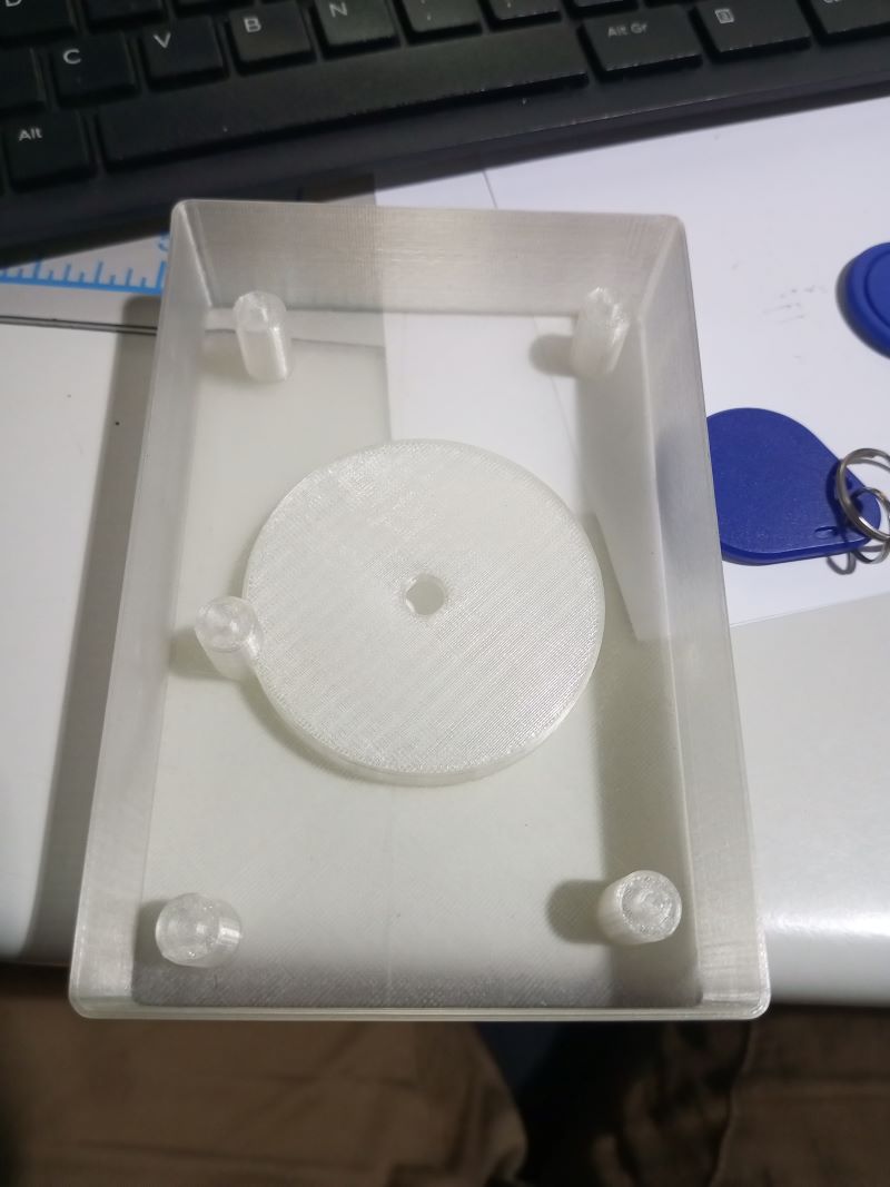
Step 2 — Mechanical Integration (Packaging)
The 3D-printed enclosure designed with Fusion 360 and printed on the Prusa i3 MK3S+ during Week 5 (3D Scanning and Printing) houses all the electronic components.
The enclosure was designed to:
- Fix the PCB securely using 4 mounting standoffs (M3)
- Route wires cleanly to avoid shorts or strain on connectors
- Expose the RFID reader flush with the front face for easy badge scanning
- Provide clear visibility of the LCD screen through a dedicated window
- Allow easy access to the USB port for firmware updates
Step 3 — Firmware Integration
The embedded firmware was developed using Arduino IDE / PlatformIO (from Week 4 - Embedded Programming and Week 11 - Networking and Communications).
The firmware manages all components simultaneously using a non-blocking architecture based on millis() timers to avoid delays in execution.
Firmware Architecture
void loop() {

    // 1. Check RFID reader for new badge scan
    checkRFID();

    // 2. Update LCD display content
    updateDisplay();

    // 3. Control servo motor (door lock)
    updateDoorLock();

    // 4. Handle Wi-Fi and WebSocket communication
    handleWebSocket();

    // 5. Update LEDs and buzzer
    updateFeedback();
}
RFID Badge Identification Logic
When a badge is presented to the reader, the firmware:
- Reads the UID (Unique Identifier) of the badge via SPI
- Compares it against the list of authorized UIDs stored in memory
- Triggers the appropriate action:
- Authorized badge → Green LED ON, buzzer short beep, servo opens the lock, LCD displays "Access Granted"
- Unknown badge → Red LED ON, buzzer long beep, door remains locked, LCD displays "Access Denied"
- Logs the event (UID, timestamp, access result) and sends it via WebSocket to the admin dashboard
Complete Firmware Code
#include <WiFi.h>
#include <WebSocketsServer.h>
#include <ArduinoJson.h>
#include <SPI.h>
#include <MFRC522.h>
#include <LiquidCrystal_I2C.h>
#include <ESP32Servo.h>

// ========================== NETWORK CONFIGURATION ==========================
const char* SSID_WIFI = "YOUR_SSID";
const char* PASS_WIFI = "YOUR_PASSWORD";

// ========================== PIN CONFIGURATION ==========================
#define PIN_RFID_SDA    5
#define PIN_RFID_RST    4
#define PIN_SERVO       13
#define PIN_LED_GREEN   25
#define PIN_LED_RED     26
#define PIN_BUZZER      27

// ========================== GLOBAL OBJECTS ==========================
MFRC522 rfid(PIN_RFID_SDA, PIN_RFID_RST);
LiquidCrystal_I2C lcd(0x27, 20, 4);
Servo doorServo;
WebSocketsServer webSocket = WebSocketsServer(81);

// ========================== AUTHORIZED BADGE LIST ==========================
String authorizedUIDs[] = {
    "A1B2C3D4",
    "12345678"
};
int authorizedCount = 2;

// ========================== TIMING VARIABLES ==========================
unsigned long lastDoorOpen = 0;
bool doorIsOpen = false;
#define DOOR_OPEN_DURATION 5000  // Door stays open 5 seconds

// ========================== FUNCTIONS ==========================
String getUID(MFRC522 &reader) {
    String uid = "";
    for (byte i = 0; i < reader.uid.size; i++) {
        if (reader.uid.uidByte[i] < 0x10) uid += "0";
        uid += String(reader.uid.uidByte[i], HEX);
    }
    uid.toUpperCase();
    return uid;
}

bool isAuthorized(String uid) {
    for (int i = 0; i < authorizedCount; i++) {
        if (authorizedUIDs[i] == uid) return true;
    }
    return false;
}

void grantAccess(String uid) {
    // Visual and audio feedback
    digitalWrite(PIN_LED_GREEN, HIGH);
    digitalWrite(PIN_LED_RED, LOW);
    tone(PIN_BUZZER, 1000, 200);

    // Open the door lock
    doorServo.write(90);
    doorIsOpen = true;
    lastDoorOpen = millis();

    // Update LCD
    lcd.clear();
    lcd.setCursor(0, 0);
    lcd.print("  ACCESS GRANTED  ");
    lcd.setCursor(0, 1);
    lcd.print("UID: " + uid);
    lcd.setCursor(0, 2);
    lcd.print("Door: OPEN");

    // Send log to dashboard
    sendLog(uid, "GRANTED");
}

void denyAccess(String uid) {
    // Visual and audio feedback
    digitalWrite(PIN_LED_GREEN, LOW);
    digitalWrite(PIN_LED_RED, HIGH);
    tone(PIN_BUZZER, 400, 1000);

    // LCD
    lcd.clear();
    lcd.setCursor(0, 0);
    lcd.print("  ACCESS DENIED   ");
    lcd.setCursor(0, 1);
    lcd.print("UID: " + uid);
    lcd.setCursor(0, 2);
    lcd.print("Door: LOCKED");

    // Send log to dashboard
    sendLog(uid, "DENIED");
    delay(2000);
    resetDisplay();
}

void sendLog(String uid, String result) {
    StaticJsonDocument<256> doc;
    doc["uid"]    = uid;
    doc["result"] = result;
    doc["time"]   = millis();
    char buffer[256];
    size_t len = serializeJson(doc, buffer);
    webSocket.broadcastTXT(buffer, len);
}

void checkDoorTimeout() {
    if (doorIsOpen && (millis() - lastDoorOpen >= DOOR_OPEN_DURATION)) {
        doorServo.write(0);
        doorIsOpen = false;
        digitalWrite(PIN_LED_GREEN, LOW);
        resetDisplay();
    }
}

void resetDisplay() {
    lcd.clear();
    lcd.setCursor(0, 0);
    lcd.print("  FABLAB INPHB  ");
    lcd.setCursor(0, 1);
    lcd.print("Scan your badge...");
}

// ========================== SETUP ==========================
void setup() {
    Serial.begin(115200);

    // Pin setup
    pinMode(PIN_LED_GREEN, OUTPUT);
    pinMode(PIN_LED_RED,   OUTPUT);
    pinMode(PIN_BUZZER,    OUTPUT);

    // LCD init
    lcd.init();
    lcd.backlight();
    resetDisplay();

    // RFID init
    SPI.begin();
    rfid.PCD_Init();

    // Servo init
    doorServo.attach(PIN_SERVO);
    doorServo.write(0);  // Door locked by default

    // Wi-Fi
    WiFi.begin(SSID_WIFI, PASS_WIFI);
    lcd.setCursor(0, 3);
    lcd.print("Connecting WiFi...");
    while (WiFi.status() != WL_CONNECTED) {
        delay(500);
        Serial.print(".");
    }
    Serial.println("\n[WIFI] Connected! IP: " + WiFi.localIP().toString());
    lcd.setCursor(0, 3);
    lcd.print("IP: " + WiFi.localIP().toString());

    // WebSocket
    webSocket.begin();
    Serial.println("[WS] WebSocket started on port 81");
}

// ========================== LOOP ==========================
void loop() {
    webSocket.loop();
    checkDoorTimeout();

    // Check for new RFID badge
    if (!rfid.PICC_IsNewCardPresent() || !rfid.PICC_ReadCardSerial()) return;

    String uid = getUID(rfid);
    Serial.println("[RFID] Badge detected: " + uid);

    if (isAuthorized(uid)) {
        grantAccess(uid);
    } else {
        denyAccess(uid);
    }

    rfid.PICC_HaltA();
    rfid.PCD_StopCrypto1();
}
Step 4 — Software Integration (Web Dashboard)
The web management dashboard was built upon the skills acquired during Week 14 (Interface and Application Programming).
It communicates with the ESP32 via WebSocket on port 81, and allows the administrator to:
- View the access log in real time (UID, result, timestamp)
- Add or remove authorized badges
- Receive visual alerts for unauthorized access attempts
Dashboard Interface
Step 5 — System Testing
Once all modules were assembled and the firmware uploaded, a series of tests were performed to validate the complete system:
Functional Tests
| Test | Description | Result |
|---|---|---|
| Authorized badge scan | Present a registered badge | Door opens, green LED, short beep ✅ |
| Unknown badge scan | Present an unregistered badge | Door stays locked, red LED, long beep ✅ |
| Auto door close | Wait 5 seconds after opening | Door closes automatically ✅ |
| LCD display | Verify all messages display correctly | Messages display properly ✅ |
| WebSocket logging | Check events appear in dashboard | Events logged in real time ✅ |
| Wi-Fi reconnection | Disconnect/reconnect router | System reconnects automatically ✅ |
Bill of Materials (BOM)
| Component | Reference | Quantity | Origin | Price ($) |
|---|---|---|---|---|
| ESP32-WROOM-32D | U1 | 1 | Digikey | $4.08 |
| RFID Reader RC522 | U2 | 1 | Amazon | $7.65 |
| LCD 20x4 I2C | LCD1 | 1 | Amazon | $10.00 |
| Servo Motor SG90 | M1 | 1 | Amazon | $3.00 |
| Buzzer 5V | BZ1 | 1 | Digikey | $0.61 |
| LED Green SMD 1206 | LED1 | 2 | Digikey | $0.78 |
| LED Red SMD 1206 | LED2 | 2 | Digikey | $0.78 |
| Reg 3.3V SOT223 | U3 | 1 | Digikey | $0.63 |
| PCB FR4 (custom) | PCB1 | 1 | FabLab | $3.00 |
| 3D Printed Enclosure (PLA) | — | 1 | FabLab | $4.50 |
| Jumper wires & connectors | — | — | FabLab | $2.00 |
| TOTAL | ~$37.03 |
Fabrication Processes Summary
| Process | Tool Used | Week |
|---|---|---|
| PCB Design | KiCad | Week 6 |
| PCB Milling | Roland SRM-20 | Week 8 |
| 3D Enclosure Design | Fusion 360 | Week 5 |
| 3D Printing | Prusa i3 MK3S+ | Week 5 |
| Vinyl cutting (labels) | Vinyl cutter | Week 3 |
| Embedded programming | Arduino IDE | Week 4 |
| Network programming | PlatformIO | Week 11 |
| Web interface | HTML / JS / WebSocket | Week 14 |
Result
After full integration, the system operates as expected:
- Authorized badges are identified instantly and the door opens for 5 seconds before locking again.
- All access events (authorized and denied) are logged in real time on the web dashboard.
- The LCD provides clear, user-friendly feedback at all times.
- The system reconnects to Wi-Fi automatically after a network interruption.