Embedded programming
Group assignment:
- Compare the performance and development workflows for other architectures.
To see our group assignment click here
Individual assignments:
- Consult the microcontroller's datasheet
- Write and test a program for an embedded system using a microcontroller interact (with input and/or output devices) and communicate (via wired or wireless connection)
- Bonus: assemble the system
- Bonus: try different programming languages and/or development environments
My individual reflection:
As a group, we compared the toolchains and development workflows of two very different architectures: the 8-bit ATmega328P (Arduino Uno) and the 32-bit ESP32.
We documented that the ATmega328P relies on a simple and mature toolchain (avr-gcc for compilation, avrdude for flashing), which makes the Arduino IDE workflow nearly instantaneous — a single click compiles and flashes the chip in seconds because there is no operating system or wireless stack to build.
In contrast, the ESP32 uses the much heavier ESP-IDF toolchain (CMake/Ninja build system, xtensa-esp32-elf-gcc compiler, esptool.py for flashing), which must additionally compile the FreeRTOS kernel and the Wi-Fi/Bluetooth network stacks before producing the final binary, resulting in noticeably longer compile times.
This comparison gave me a much clearer understanding of the trade-off between simplicity and capability in embedded development: the ATmega's toolchain is fast and easy to reason about but limited to bare-metal, single-task programs, while the ESP32's toolchain is more complex to set up but unlocks multitasking (via FreeRTOS), wireless connectivity, and far more computing headroom.
Introduction to the project
For this embedded programming work, I will use a XIAO RP2040 from Seeed Studio. This choice is motivated by its extremely compact format (stamp format), its low cost, and, above all, the power of its RP2040 chip, a dual-core ARM Cortex-M0+ microcontroller running at up to 133 MHz.
Analysis of the Datasheet : XIAO RP2040
Presentation of XIAO RP2040
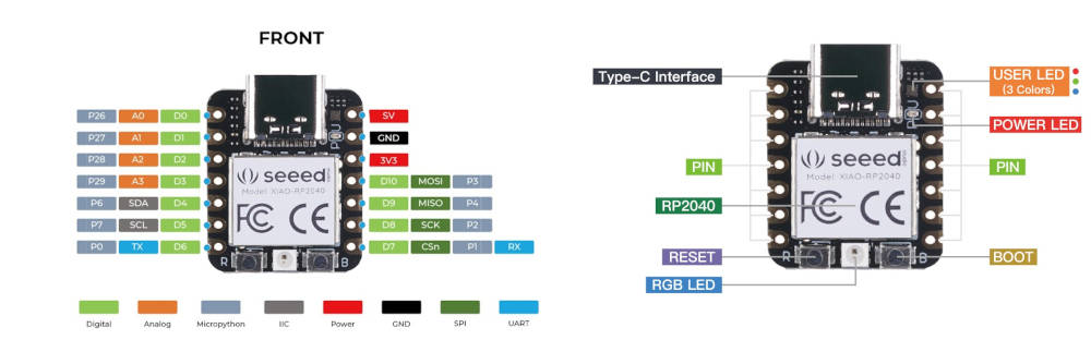
The Seeed Studio XIAO RP2040 is an ultra-compact development board designed for connected projects. Equipped with a dual-core 32-bit ARM Cortex-M0+ processor, it measures only 21 x 17.5 mm, making it ideal for wearables or miniature objects.
Thanks to its low energy consumption, it is perfectly suited for portable systems. Versatile, it supports multiple programming languages, including C/C++ (Arduino), MicroPython, and CircuitPython.
Descriptive technique
| Category | Specification | Details |
|---|---|---|
| Board Name | XIAO RP2040 | Developed by Seeed Studio |
| Microcontroller | RP2040 | Dual-core ARM Cortex-M0+ |
| CPU Frequency | Up to 133 MHz | 32-bit dual-core processor |
| SRAM | 264 KB | On-chip SRAM |
| Flash Memory | 2 MB | External QSPI Flash |
| Operating Voltage | 3.3 V | Logic level: 3.3 V |
| Input Voltage (VIN) | 5 V | Via USB Type-C |
| GPIO Pins | 11 Digital I/O | Multiplexed functions |
| Analog Inputs | 4 ADC Channels | 12-bit ADC resolution |
| PWM Channels | Up to 16 PWM channels | Flexible PWM slices |
| Communication Interfaces | UART, I2C, SPI | Multiple hardware interfaces |
| USB Interface | USB Type-C | USB 1.1 with device and host support |
| Onboard LED | Yes | User programmable LED |
| Onboard Reset Button | Yes | Reset button available |
| Antenna | No | No wireless connectivity onboard |
| Security Features | ROM Bootloader | UF2 drag-and-drop programming |
| Low Power Modes | Sleep & Dormant modes | Suitable for low-power applications |
| Dimensions | 21 mm × 17.5 mm | Ultra-compact form factor |
| Mounting Type | SMD castellated pads | Breadboard-friendly design |
| Programming Support | Arduino, MicroPython, CircuitPython, C/C++ SDK | Wide ecosystem support |
| Typical Applications | Embedded systems, Robotics, Education, Prototyping | Compact high-performance MCU board |
What I learned from the datasheet:
Reading the datasheet before wiring anything up changed several concrete decisions in my implementation.
First, the GPIO table confirmed that the RP2040 pins are strictly 3.3V logic, not 5V-tolerant
Second, the datasheet's note on the UART interface and its default baud rates guided my choice of 115200 bps in the serial monitor sketch (Arduino Code 2), since this is the highest commonly-supported rate that remains reliable over USB-CDC.
Finally, seeing that the RP2040 has no onboard antenna or wireless radio (confirmed by the "Antenna: No" row) clarified early on that any communication in this assignment would have to be wired (USB serial).
Hardware Configuration and Components
To implement and program the Seeed Studio XIAO RP2040, we utilized a specific set of components to test the microcontroller's input/output (I/O) interactions and communication capabilities:
List of Used Components:
- Microcontroller: Seeed Studio XIAO RP2040 (dual-core ARM Cortex-M0+, no onboard wireless connectivity).
- Connection Interface: A USB-C cable for both power supply and code uploading (data transfer).
- Output Peripherals: An external LED
- Input Peripherals: A push-button
Software and Programming Languages
To explore the full potential of the XIAO RP2040 and meet the "Bonus" requirements of the week, I experimented with multiple development environments and programming languages:
Arduino IDE (C++)
The Arduino IDE was my primary environment for its reliability and extensive library support.
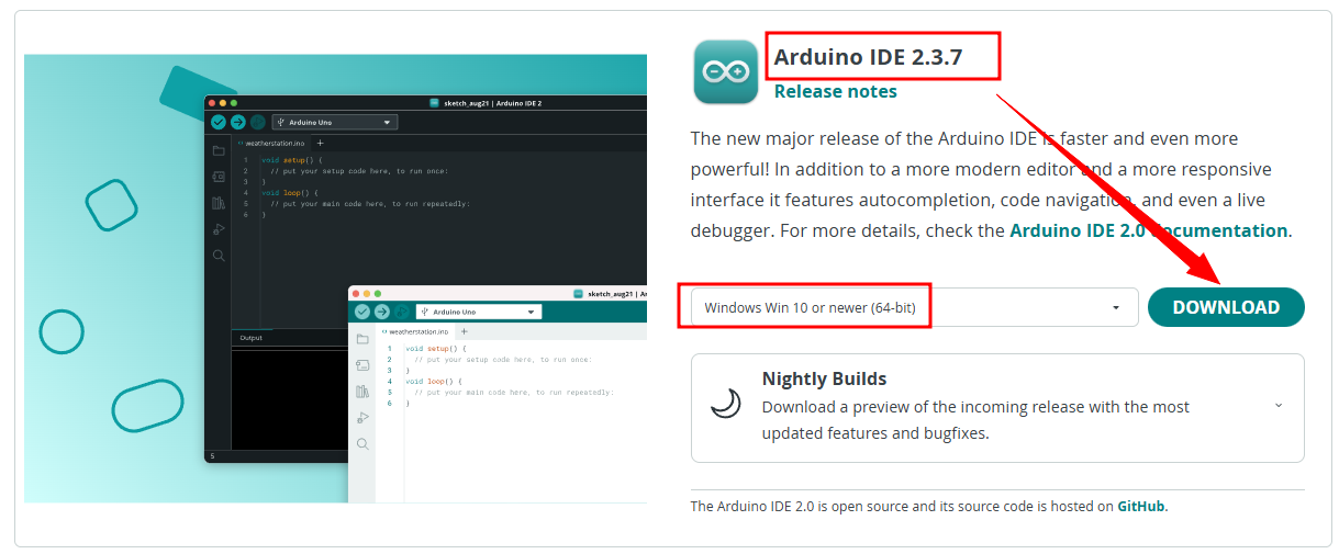
Download the Arduino software for free from the official Arduino website. We downloaded version 2.3.7.
- On Windows: run the downloaded
.exefile. - Click on
Install, then wait until the process is complete. Once finished, click onFinish. - Open the Arduino IDE. The main interface appears with:

After installing the Arduino IDE, we add the Seeed Studio XIAO RP2040 board package so that we can program it directly from within the Arduino environment.
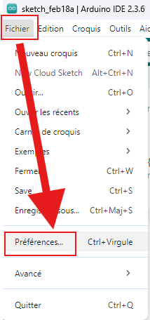
- Go to File > Preferences and enter the URL below in the Additional Boards Manager URL field:
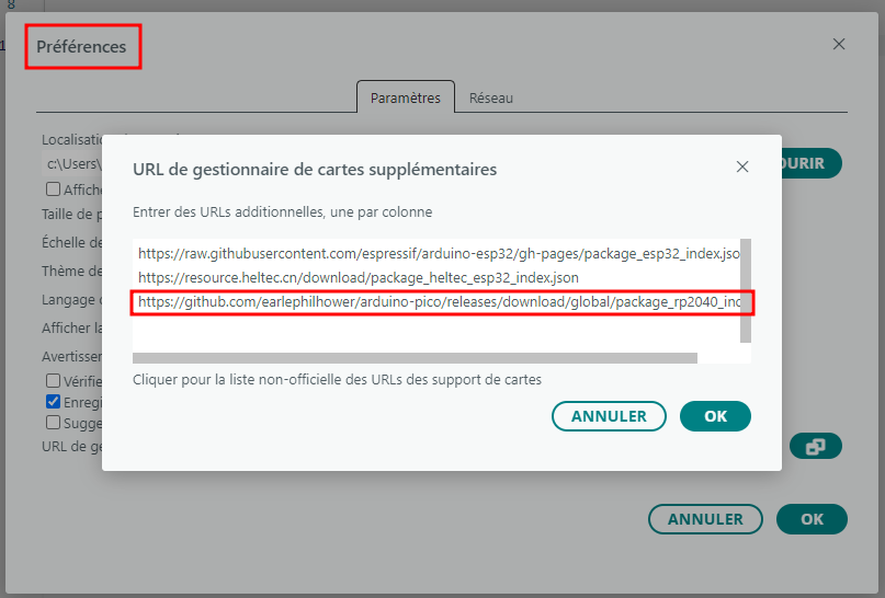
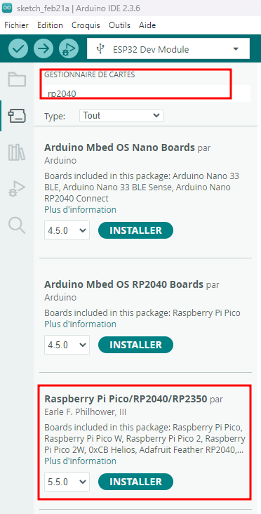
- Go to Board Manager, type rp2040, and download the map outlined in red in the image below.
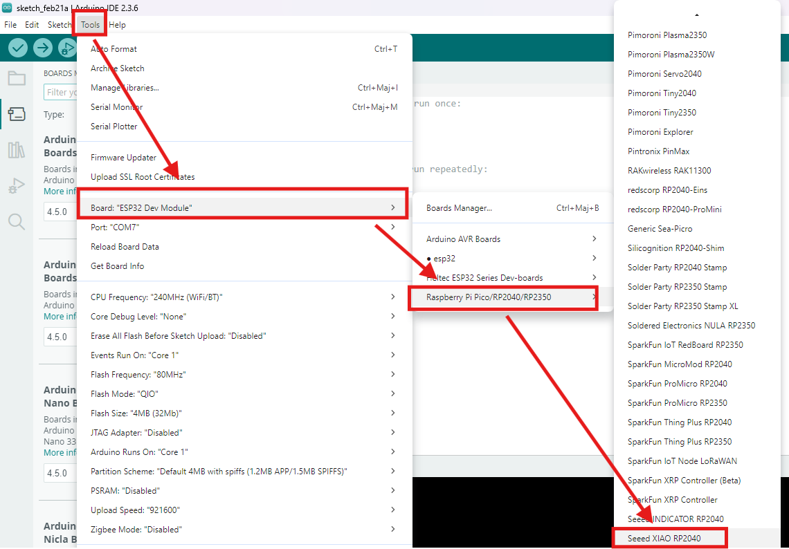
- Go to the Tools tab and follow the diagram below to choose the right card.
Programming
For programming the Seeed Studio XIAO RP2040 board, we opted to control an LED (turning it on or off) via a push button or the serial monitor commands in the Arduino IDE.
the wiring
For the wiring of our LED and push button, we used the Fab-Xiao designed by ADRIAN TORRES, as shown below.
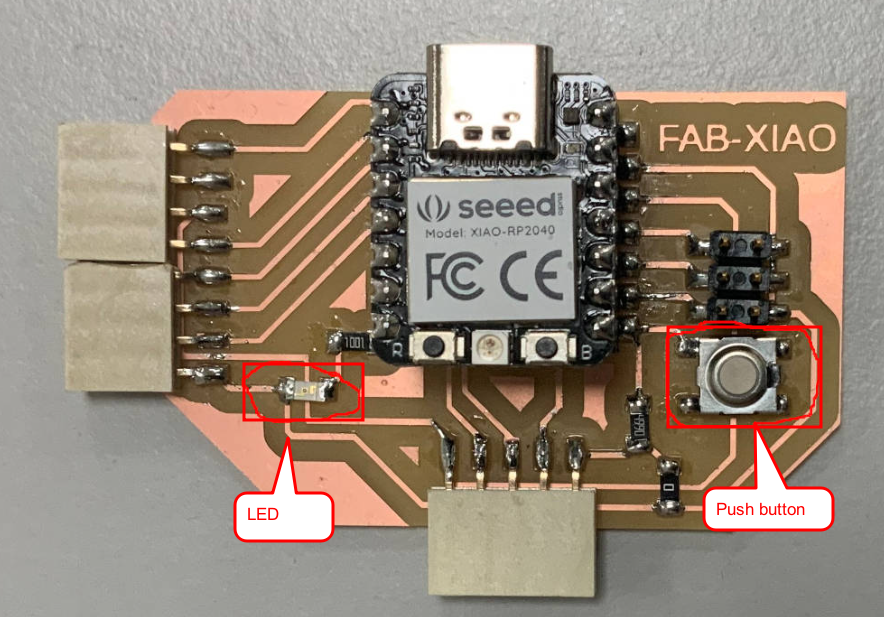
Note
- The LED is connected to pin D6.
- The button is connected to pin D7.
Arduino Code 1 : Turn an LED on or off with a button
Code Source : Arduino_xiao_rp2040_program_1.ino
#define buttonPin D7    // the number of the button pin
#define ledPin D6       // the number of the LED pin

int buttonState = 0;    // variable for reading the button status

void setup() {
  // initialize the LED pin as an output
  pinMode(ledPin, OUTPUT);
  // initialize the button pin as an input
  pinMode(buttonPin, INPUT);
}

void loop() {
  // read the state of the button value
  buttonState = digitalRead(buttonPin);

  // check if the button is pressed
  if (buttonState == HIGH ) {
    // turn on LED
    digitalWrite(ledPin, HIGH);
  }
  else {
    // turn off LED
    digitalWrite(ledPin, LOW);
  }
}
Connect your board to your PC using a USB Type-C cable, then go to Tools > Port and select the serial port name for the connected Seeed Studio XIAO RP2040, as shown below.
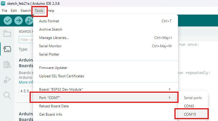
Click the Upload button to flash the code onto the board, as shown below. If the upload succeeds, the message will be highlighted in red.
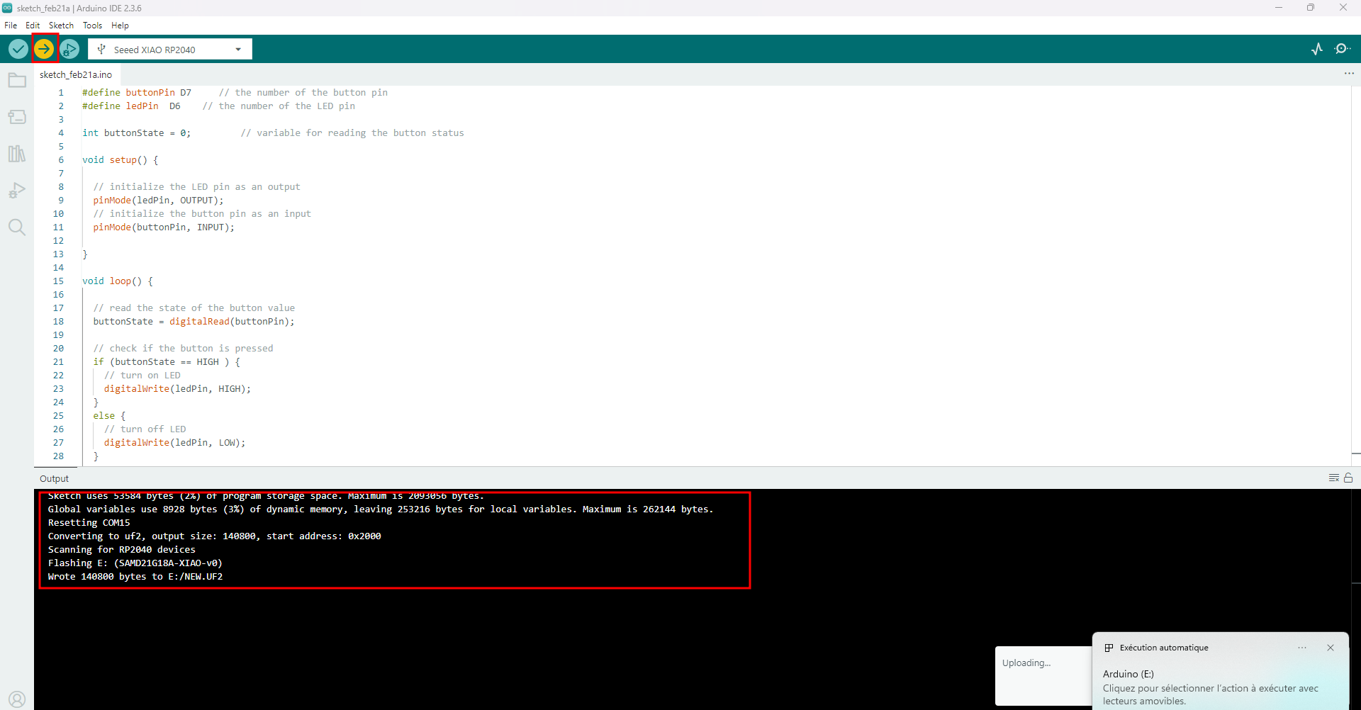
Congratulations! Your code has been successfully compiled and uploaded to your Seeed Studio XIAO RP2040.
Arduino Code 2 : Turning an LED on or off with the Arduino IDE serial monitor
Code Source : Arduino_xiao_rp2040_program_2.ino
#define ledPin  D6    // the number of the LED pin

String msg ; // data recording variable received

void setup() {

  Serial.begin(115200); // Opens serial port, sets data rate to 115200 bps
  pinMode(ledPin, OUTPUT);
}

void loop() {

  // reply only when you receive data
  if (Serial.available() > 0) {

    msg = Serial.readString();// read the data received
    msg.trim(); // remove any \r \n whitespace at the end of the String

    if (msg  == "ON") {
      digitalWrite(ledPin, HIGH);
      Serial.println("The LED is ON");
     }
    else if (msg == "OFF") {
      digitalWrite(ledPin, LOW);
      Serial.println("The LED is OFF");
     }
   }

 }
2. Thonny IDE (MicroPython)
I used Thonny to explore a more modern, interpreted approach to embedded systems.
MicroPython is a lean implementation of Python 3 designed as an interpreter for microcontrollers, featuring a trimmed-down standard library optimized for resource-constrained devices.
For more details, visit the official MicroPython site. To run MicroPython, we used the Seeed Studio XIAO RP2040 board with the Thonny Python IDE.
Installation Steps
Thonny installation is straightforward: head to https://thonny.org/, download the version matching your operating system (Windows in our case), and proceed as shown below.
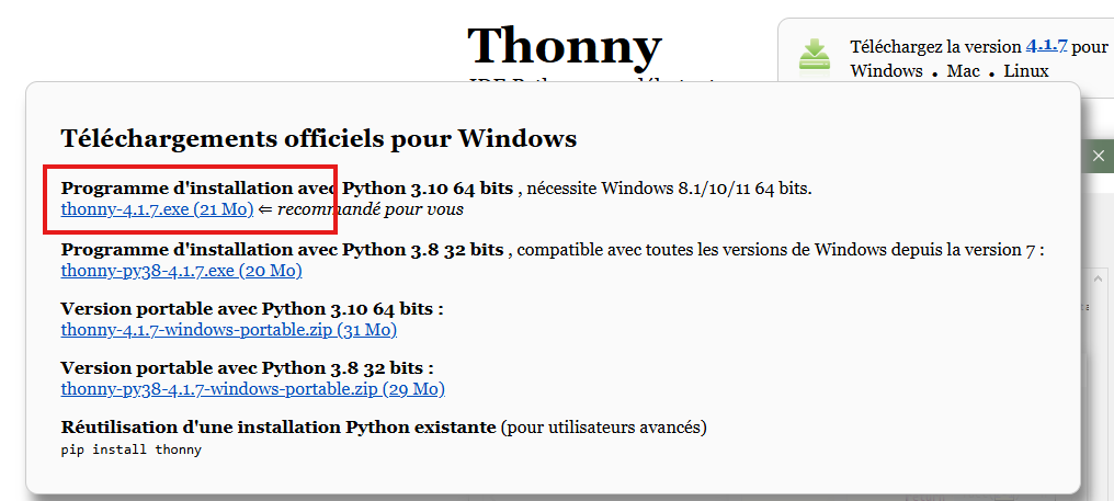
After installation,
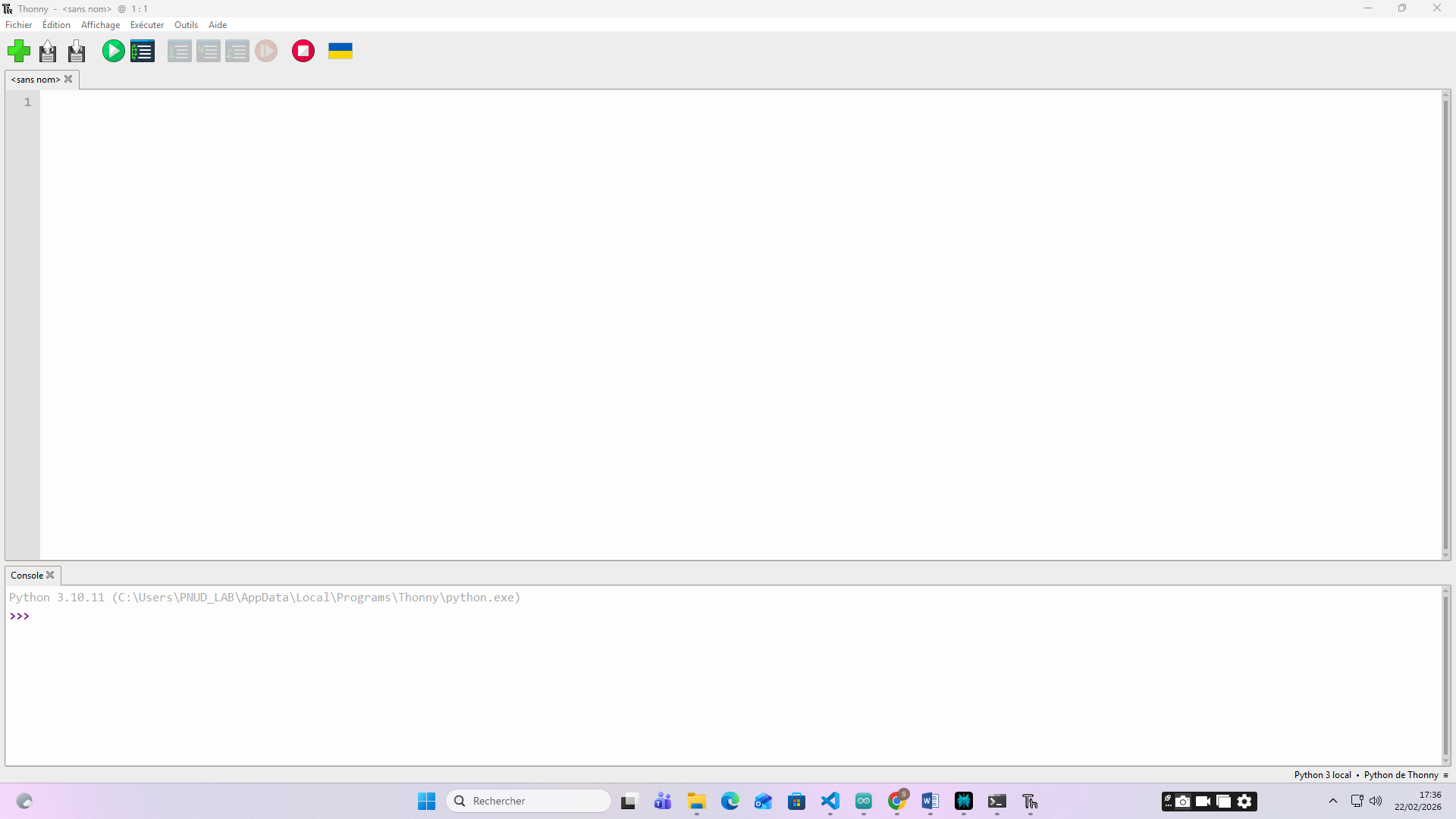
connect your XIAO RP2040 via USB Type-C, and in Thonny, select the interpreter under Tools > Options > Interpreter (choose "MicroPython (Raspberry Pi Pico)" for RP2040 compatibility).
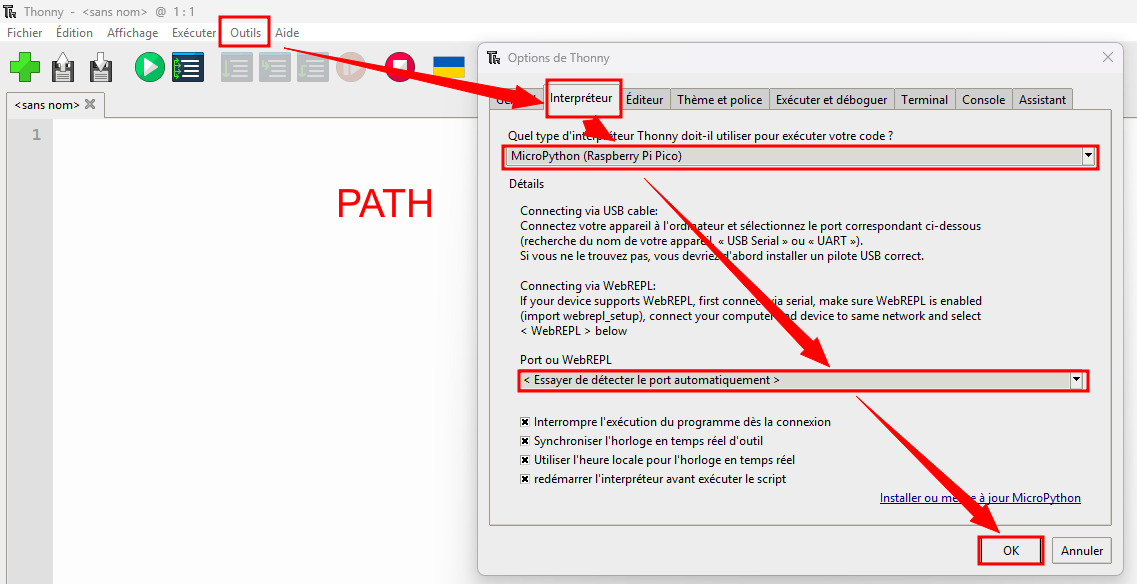
Flash the MicroPython UF2 firmware by double-pressing the BOOT button on the board, then drag the UF2 file to the mounted drive.
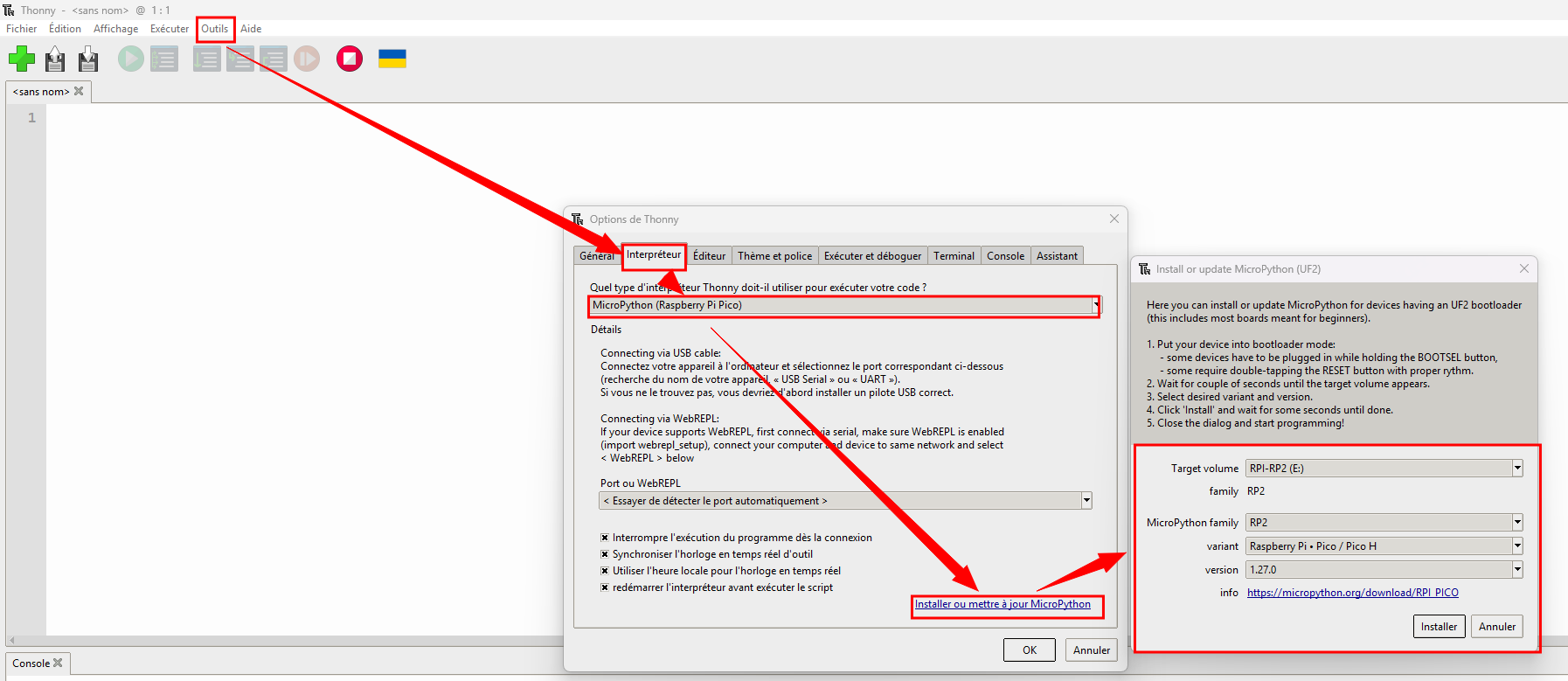
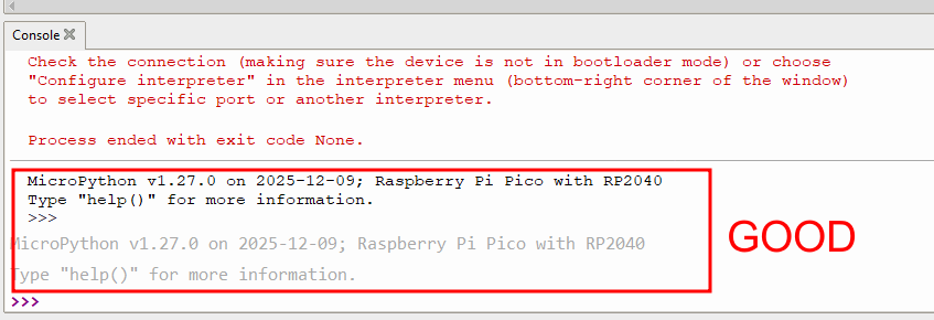
Once the installation is complete, click "Close". If successful, the following confirmation window should appear.
Micropython Code 1 : Turn an LED on or off with a button
from machine import Pin, Timer

led = Pin(0, Pin.OUT)
button = Pin(1, Pin.IN)

led.high()

while True:

    if button.value() == 1 :
        led.high()
    else :
        led.low()
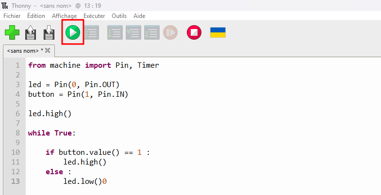
Click the Run button to upload the code, as shown below.