11. Networking and communications
Group assignment:
- Send a message between two projects
To see our group assignment click here
Individual assignment:
- Design, build, and connect wired or wireless node(s) with network or bus addresses
My contribution to the group characterization test
During the group characterization test, I contributed Board 1 (ESP32 + DHT11 + LED). My part of the test was to validate the ESP-NOW protocol in a bidirectional configuration: my board continuously read temperature and humidity from the DHT11 sensor and sent this data via ESP-NOW to the XIAO ESP32S3 board, while simultaneously receiving the push-button state from that board to turn my LED on or off.
I first tested the protocol by retrieving the MAC address of each board, then verified
that the peer registration (esp_now_add_peer) worked correctly on both sides. Once
this was done, I observed that the DHT11 readings were transmitted every 2 seconds
with a very low latency, and the LED responded almost instantly to the button state
received from the other board.
Introduction to the project
The goal of this week’s project is to design a bidirectional wireless communication system between two ESP32 microcontrollers using the ESP-NOW protocol. The objective is to create a cross-interaction system where pressing a physical button on the first board instantly turns on an LED on the second board, and vice versa.
Unlike standard Wi-Fi communication, which requires an internet router or access point, ESP-NOW enables a direct, fast, and low-power connection between the ESP32 boards.
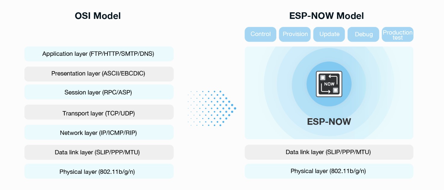
ESP-NOW Communication Protocol
ESP-NOW is a wireless communication protocol developed by Espressif that enables direct communication between multiple ESP32 or ESP8266 boards without requiring a central Wi-Fi router. It is a highly efficient solution for automation, IoT, and robotics projects.
1. Main Features
ESP-NOW stands between Bluetooth and traditional Wi-Fi in terms of usage.
-
Router-Free Communication:
Devices communicate directly in a Peer-to-Peer manner. -
Low Latency:
Communication is almost instantaneous because there is no complex Wi-Fi handshake process. -
Low Power Consumption:
Ideal for battery-powered nodes that need to wake up, send data, and return to sleep quickly. -
Range:
Similar to standard Wi-Fi, typically between 30 and 100 meters in open space depending on the antenna. -
Capacity:
One node can be paired with up to 20 registered devices.
2. Architecture and Addressing
Unlike traditional Wi-Fi, which uses IP addresses, ESP-NOW relies on the unique MAC address of each ESP32 or ESP8266 chip.
Possible Topologies
-
One-to-One:
One controller communicates with a single slave device. -
One-to-Many:
One master sends commands to several nodes
(e.g., one remote controller operating multiple motors). -
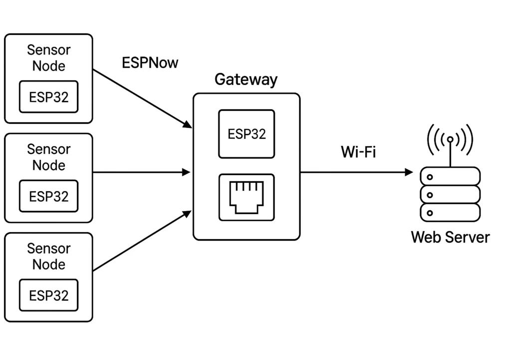
Many-to-One:
Several sensors send their data to a central gateway
(e.g., a multi-sensor weather station).
3. Communication Workflow
To establish communication, the program follows these critical steps:
1. Wi-Fi Initialization
The ESP32 is configured in Station Mode.
2. MAC Address Retrieval
The receiver must provide its MAC address to the transmitter.
3. Peer Registration
The transmitter adds the receiver’s MAC address to its peer list.
4. Callback Management
ESP-NOW uses callback functions for event handling.
Data Sent Confirmation
This function confirms whether the packet was successfully delivered.
Data Reception
This function is automatically triggered when data is received.
ESP-NOW Communication Setup
Setting up ESP-NOW follows a rigorous logic that transforms your ESP32 boards into real wireless network terminals. For the two boards to exchange the states of their buttons and LEDs, four key steps are required: preparation, addressing, data structuring, and event management through callbacks.
1. Preparation Phase (Station Mode)
Even though ESP-NOW does not require an internet connection, it still uses the ESP32’s Wi-Fi radio module. For this reason, the chip must be initialized in Station Mode (STA).
This mode allows the ESP32 to: - Activate its MAC address - Listen for packets coming from other devices - Participate in ESP-NOW communication
2. Addressing: “Who Talks to Whom”
This is the most critical step.
In ESP-NOW, communication is not based on IP addresses, but on MAC addresses. Each ESP32 has a unique physical identifier made of 6 bytes.
Example:
Peer Pairing
To establish communication:
- The MAC address of Board B must be registered inside Board A
- This registration process is called pairing (peer_info)
Without this step, the ESP32 will refuse to send data for security and optimization reasons.
3. Data Structure (The Message)
For both boards to understand each other, they must use the same data format.
This is achieved using a C++ structure (struct).
Example:
In this project: - The structure contains a single boolean value - It indicates whether the button is pressed or released
Whenever the button state changes, the ESP32 places the value into the structure and sends it wirelessly.
4. Callback Functions (The Operator)
The ESP32 does not continuously wait for messages. Instead, it uses callback functions, which work like an operator reacting automatically to events.
Sending Callback
This function is automatically executed after sending data.
It confirms whether: - The message was successfully delivered - Or the transmission failed
Receiving Callback
This is the most important callback for the project.
As soon as a packet arrives: - The ESP32 processor is immediately notified - The received value is read - The LED state is updated instantly
Example:
5. Communication Flow in the Project
The system works according to the following sequence:
-
Action:
You press the button on Board A -
Detection:
Theloop()function detects the state change -
Transmission:
Board A sends thestructpacket to the MAC address of Board B -
Reception:
Board B receives the packet and activatesOnDataRecv() -
Execution:
Board B reads the received value and turns the LED ON or OFF
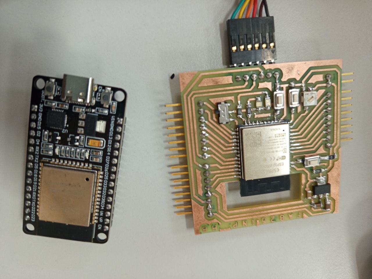
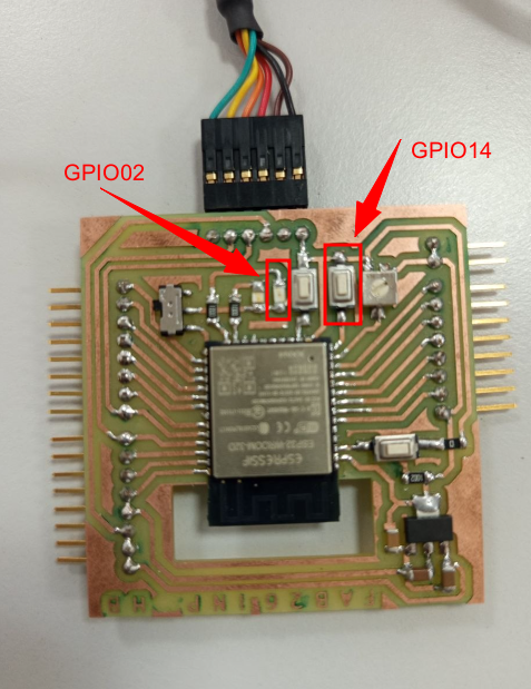
Here are our ESP32 boards :
The assembly
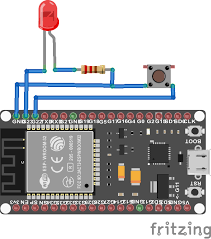
I used the following image as inspiration for my wiring setup.
Of course, I modified the GPIO pin assignments according to the specific requirements of my project.
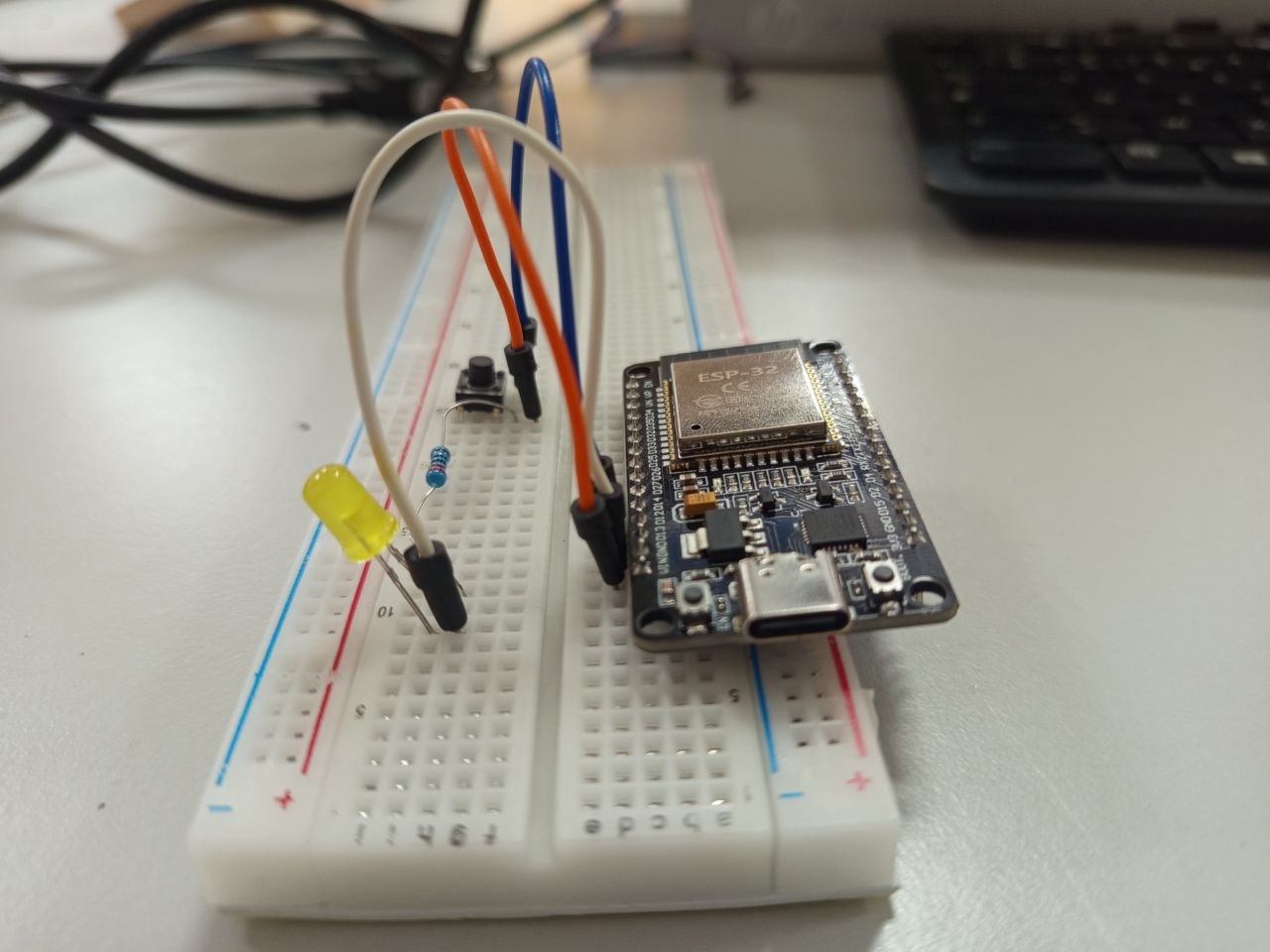
On the electronic board designed during Week 6, I integrated several LEDs and push buttons that will be used for this project.
Once the wiring is complete on both boards, I'm ready to move on to uploading the code.
ESP-NOW Bidirectional Communication Implementation
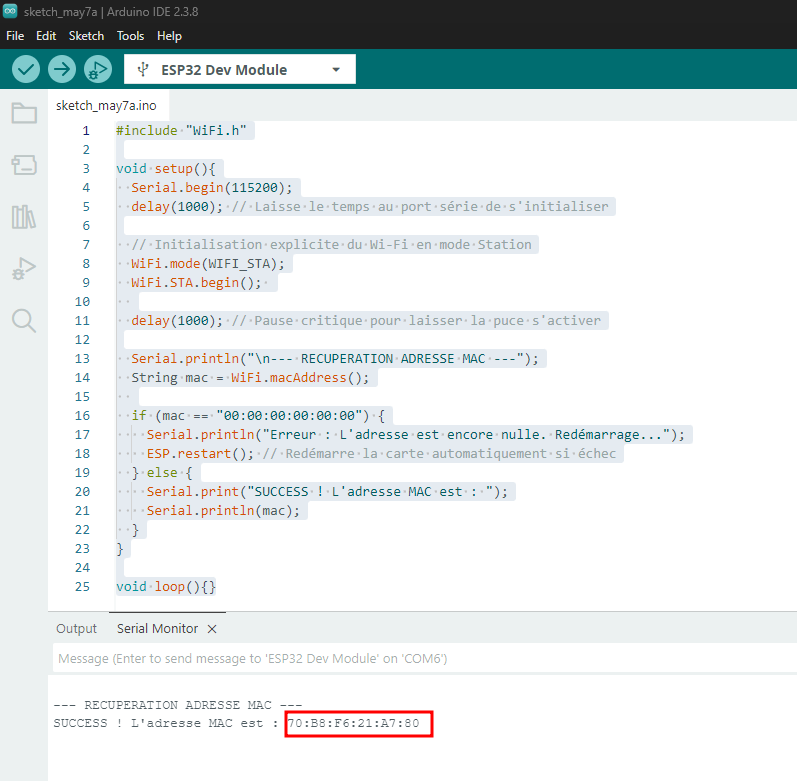
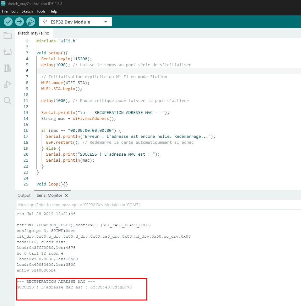
For this project to work correctly, you must first retrieve the MAC address of each ESP32 board, then upload the main program while reversing the addresses between the two boards.
Step 1: Retrieve the MAC Addresses
Upload the following code to Board A, open the Serial Monitor at 115200 baud, and note the displayed MAC address. Repeat the same procedure for Board B.
#include "WiFi.h"

void setup(){
  Serial.begin(115200);
  delay(1000); // Laisse le temps au port série de s'initialiser

  // Initialisation explicite du Wi-Fi en mode Station
  WiFi.mode(WIFI_STA);
  WiFi.STA.begin();

  delay(1000); // Pause critique pour laisser la puce s'activer

  Serial.println("\n--- RECUPERATION ADRESSE MAC ---");
  String mac = WiFi.macAddress();

  if (mac == "00:00:00:00:00:00") {
    Serial.println("Erreur : L'adresse est encore nulle. Redémarrage...");
    ESP.restart(); // Redémarre la carte automatiquement si échec
  } else {
    Serial.print("SUCCESS ! L'adresse MAC est : ");
    Serial.println(mac);
  }
}

void loop(){}
Step 2: Main Communication Code
The following program is identical for both ESP32 boards.
The only difference is the value of:
Code for Board A
In this code, replace the MAC address with the MAC address of Board B.
#include <esp_now.h>
#include <WiFi.h>

// --- CONFIGURATION ---
// REPLACE with the MAC address of BOARD B
uint8_t broadcastAddress[] = {0xFF, 0xFF, 0xFF, 0xFF, 0xFF, 0xFF};

const int ledPin = 2;
const int buttonPin = 4;

// Data structure
typedef struct struct_message {
    bool buttonPressed;
} struct_message;

struct_message myData;
struct_message incomingData;

// Callback function triggered when data is received
void OnDataRecv(const uint8_t * mac, const uint8_t *data, int len) {

  memcpy(&incomingData, data, sizeof(incomingData));

  digitalWrite(ledPin, incomingData.buttonPressed ? HIGH : LOW);
}

void setup() {

  Serial.begin(115200);

  pinMode(ledPin, OUTPUT);
  pinMode(buttonPin, INPUT_PULLUP);

  WiFi.mode(WIFI_STA);

  // Initialize ESP-NOW
  if (esp_now_init() != ESP_OK) {
    Serial.println("ESP-NOW initialization error");
    return;
  }

  // Register receive callback
  esp_now_register_recv_cb(esp_now_recv_cb_t(OnDataRecv));

  // Register peer device
  esp_now_peer_info_t peerInfo;

  memcpy(peerInfo.peer_addr, broadcastAddress, 6);

  peerInfo.channel = 0;
  peerInfo.encrypt = false;

  if (esp_now_add_peer(&peerInfo) != ESP_OK) {
    Serial.println("Failed to add peer");
    return;
  }
}

void loop() {

  // Read button state (inverted because of INPUT_PULLUP)
  bool currentState = !digitalRead(buttonPin);

  // Send data only if state changes
  if (currentState != myData.buttonPressed) {

    myData.buttonPressed = currentState;

    esp_err_t result = esp_now_send(
      broadcastAddress,
      (uint8_t *) &myData,
      sizeof(myData)
    );

    if (result == ESP_OK) {
      Serial.println("Message sent successfully");
    } else {
      Serial.println("Transmission error");
    }
  }

  // Small debounce delay
  delay(50);
}
Code for Board B
Use exactly the same code as above, but replace the MAC address with the MAC address of Board A.
// REPLACE with the MAC address of BOARD A
uint8_t broadcastAddress[] = {0x00, 0x00, 0x00, 0x00, 0x00, 0x00};
Explanation of Key Parts of the Code
1. INPUT_PULLUP Configuration
The ESP32 uses its internal pull-up resistor.
- The button is connected to GND
- When the button is pressed:
returns
LOW
This is why the code uses:
to convert the pressed state into true.
2. Sending Data
This function sends the myData structure containing the button state.
3. Receiving Data
This callback function acts as the reception “brain” of the system.
As soon as a packet arrives: - The received structure is copied - The LED state is updated instantly
4. State Change Detection
This condition ensures that data is sent only when the button state changes.
This avoids: - Sending thousands of unnecessary packets - Wasting energy - Saturating the wireless channel
Final Result
Once both boards are flashed with their respective programs:
- Pressing the button on Board A turns on the LED on Board B
- Pressing the button on Board B turns on the LED on Board A
The communication occurs almost instantly thanks to the low latency of ESP-NOW.