7. Computer controlled machining
Group assignment:
-
Complete your lab’s safety training
-
Test runout, alignment, fixturing, speeds, feeds, materials and toolpaths for your machine
-
Document your work to the group work page and reflect on your individual page what you learned
To see our group assignment click here
Individual assignment:
-
Make (design+mill+assemble) something big(~meter-scale)
-
extra credit: don’t use fasteners or glue
-
extra credit: include curved surfaces.
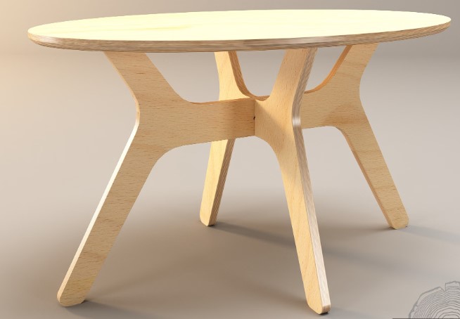
For this week’s assignment, we decided to design and build a table using the Shopbot Alpha 96. The material used will be MDF.
here’s the table model we want to make. it’s a dining table, a study table, a meeting table .... it all depends on the user.
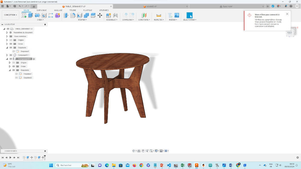
Sketch
The images below show the design process for the various parts of the table.
Picture 01

Picture 02

Picture 03
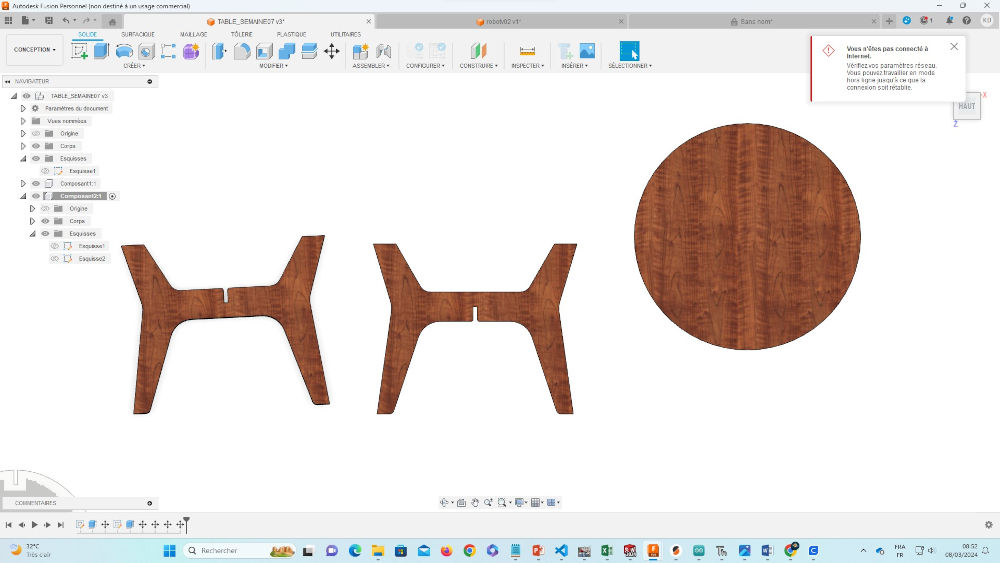
Picture 04
Mistake
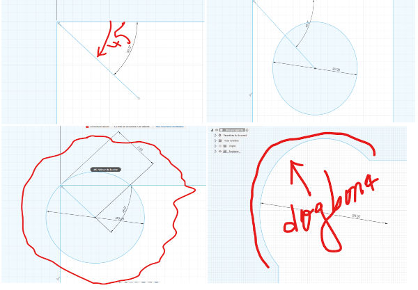
Now that we’ve finished modelling, let’s see if our table will hold up when we go to cutting. in the following image, you can see that the angle chosen for the legs will make it difficult for the tabletop to fit in. you can see this at the ends circled in red.

To correct this, we’re going to make the angle of the part of the feet that enters the tray straight with a height of 9mm. On the following figure, you can see the parite we’re hoping to make straight.

On the following image, depending on the hollow we want to make, we’ve modified the angle to obtain what you see.
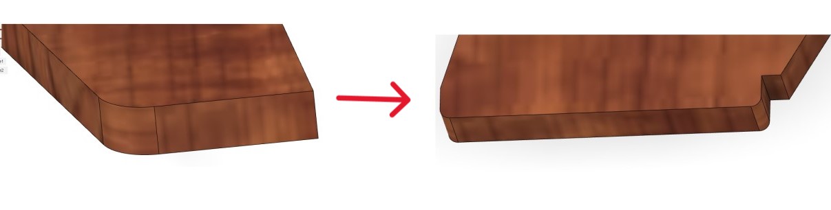
After adjusting the angle, you’ll notice that the tabletop and table are now bonded together.

One important thing not to forget: you need dogbins for easy and simple assembly.

To put the dogbones here are some link that will take you to the youtube video we watched:
When you’ve finished modeling, place your models on the front plane and save in .DXF format.

For Safety
Before accessing the shopbpt, it is imperative to strictly follow the established safety instructions. This includes wearing appropriate personal protective equipment, such as hard hats, safety shoes and gloves. In addition, it is crucial to comply with the safety rules and standard operating procedures in force for the use of equipment and machinery in shopbpt. Any deviation from these instructions may jeopardize your safety and that of others, as well as the smooth running of operations.
the protective equipment we use is as follows
        - Surrounded in red are the wood chip protection bezels.
        - Surrounded in blue are protective gloves.
        - Surrounded in yellow are the anti-fog helmets.
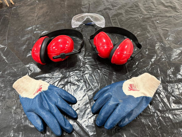
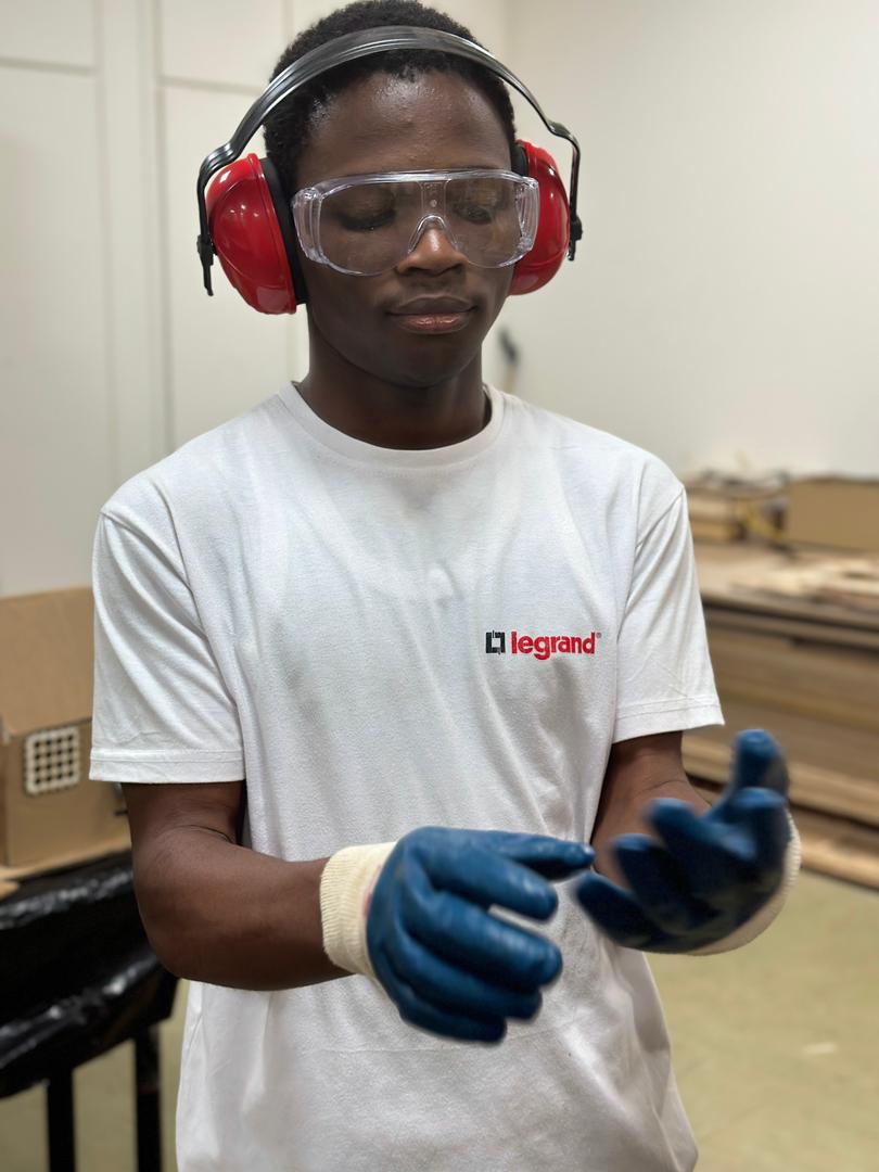
Do as I do 😁😊😊
Tools
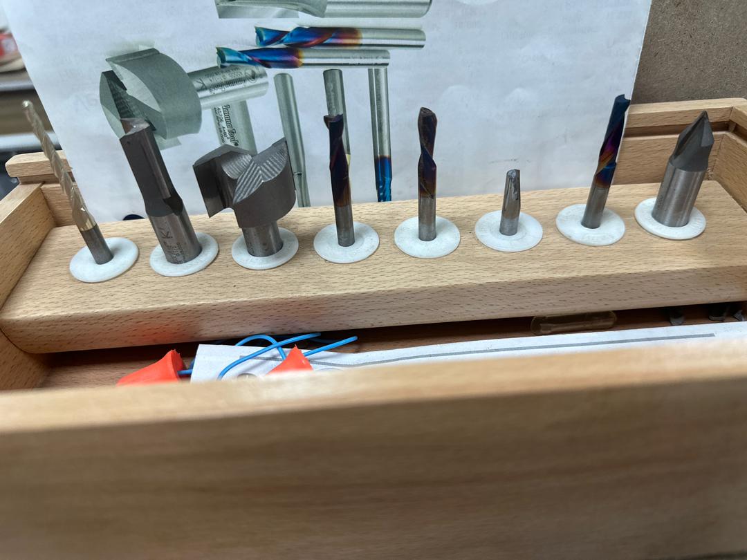
The image below shows the tools you can use on the ShopBot. Each tool has its precise role, some are used for wood, others for steel, plastic…

Tool installation
All we’ll be doing is cutting, for which we’ll use Spiral flute plunge as shown in the image below.
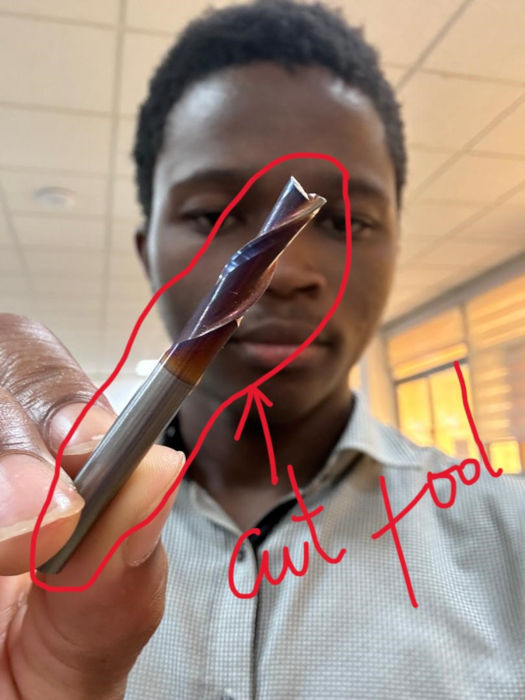
Thanks to its helical flute design, this cutter enables efficient chip evacuation, reducing the risk of jamming and overheating, and thus improving the quality of the finish. The cutter’s ability to penetrate material vertically facilitates the creation of cavities and pockets with great precision, while minimizing stress on the machine and tool.
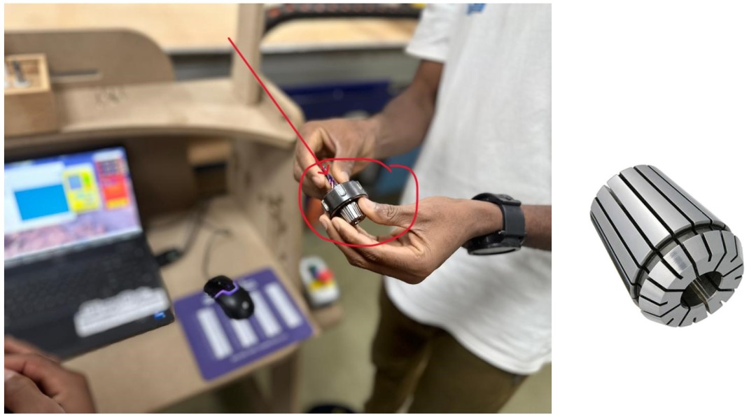
- Insert tool into collar
First, you need to insert the tool into an object called a collar, as shown in the image.
- Insert collar into ShopBot orifice
After inserting the tool into the collar, take the assembly and attach it to the machine as shown in the image below.
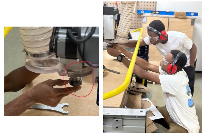
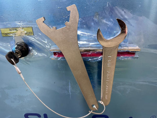
- Use the following keys to tighten the collar
Push the tool lightly towards you, then use the wrenches to tighten it.
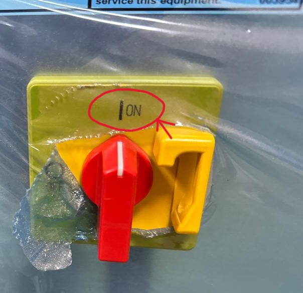
- Switch on our machine by turning the rotary knob to ON.
V-carve
VCarve allows users to create 2D and 2.5D models, as well as toolpath generation tools for cutting, engraving and machining various materials. It offers a user-friendly interface and powerful features to design parts accurately and efficiently for CNC production.
This software is widely used in fields such as joinery, sign-making, engraving and other applications requiring precise, customized manufacturing operations.
Toolpath generation with V-carve
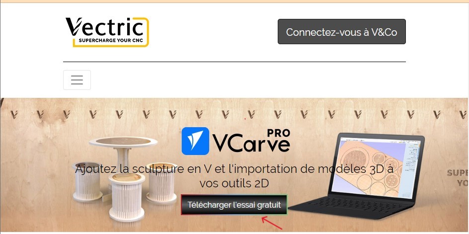
After downloading the software, install it and open it.

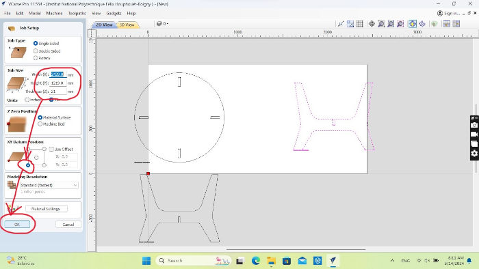
- Enter the dimensions of the material you want to use. In our case it is a plywood whose dimensions are :
Click on OK
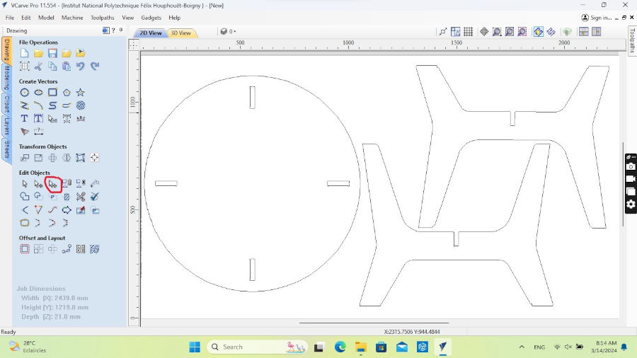
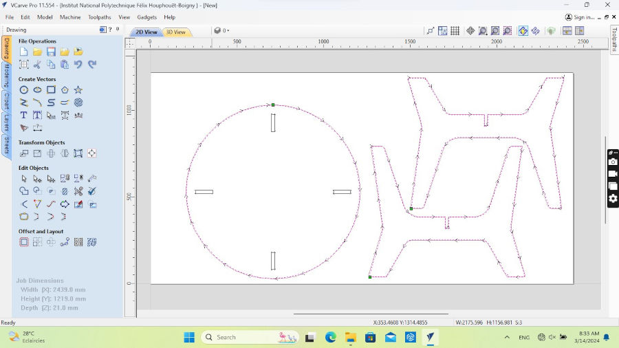
- Use the tool circled in red to arrange your shapes on the white rectangle. See image below
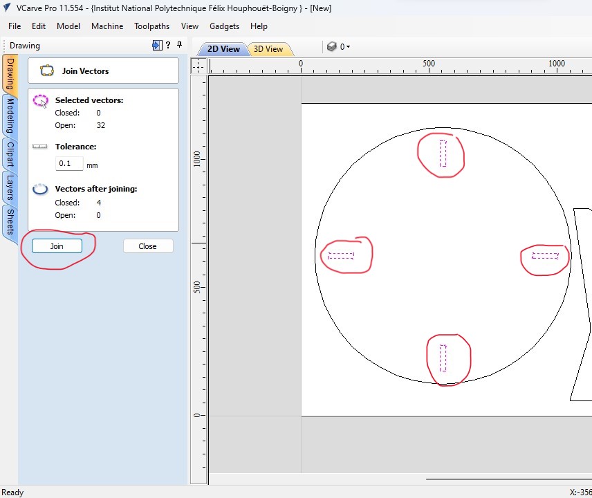
- To join elements of the same shape, select the shape as circled in red > Join vectors > click Join.
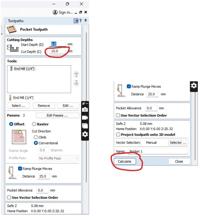
- the elements selected above will enable us to make pockets in the material to attach the table legs. to do this, do : Toolpaths > Pocket Toolpath

- Double-click on the Pocket Toolpath symbol and a window will appear. We want to make a 15 mm pocket, so do :
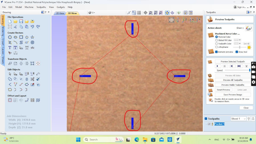
You should see the following image on your screen. It shows you a preview of the pocket the tool will make. If you’re satisfied, click Close.
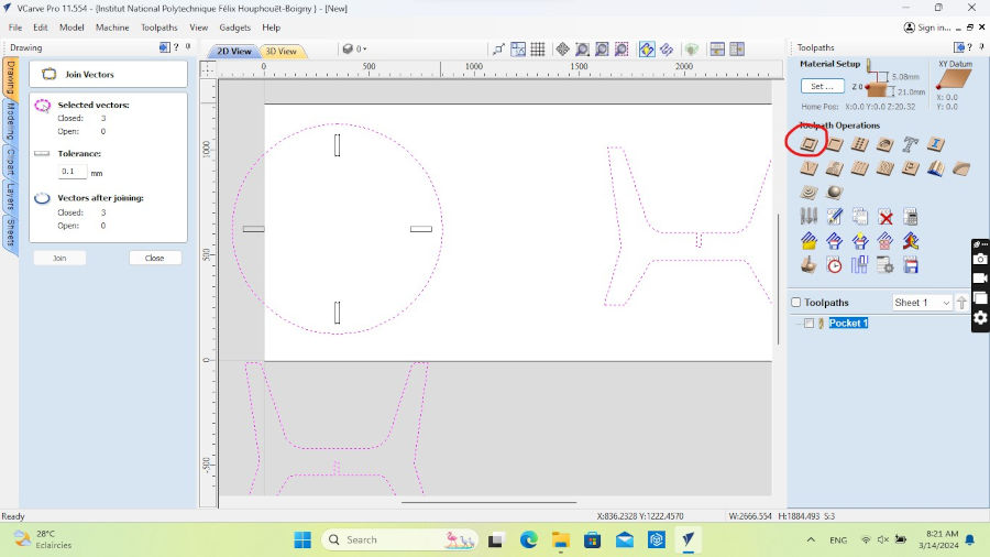
- Now select the other contours to be cut and click on the object circled in red (2D Profile Toolpath)
- In 2D Profile Toolpath, put :
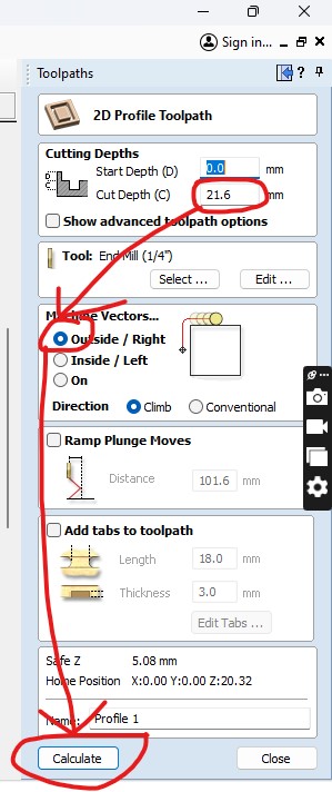
You should see the following image on your screen. It shows the path of your tool during cutting.

If you’re satisfied, click on Close and you’ll see the path your tool will take as a vector.
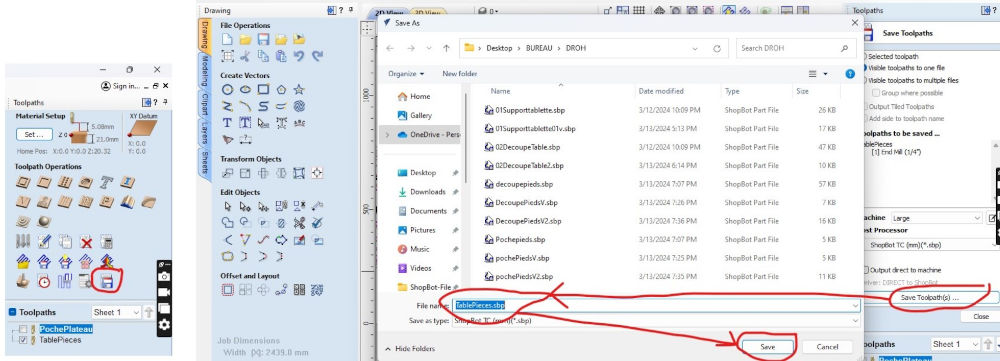
- You can save your files by clicking on the object circled in red, name it and save.
On ShopBot software
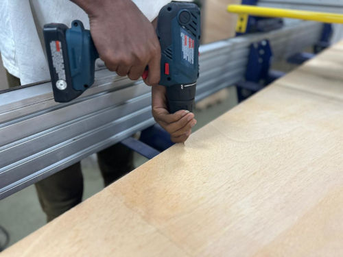
- Secure your board with spikes to prevent the wood from shifting during cutting and causing damage.
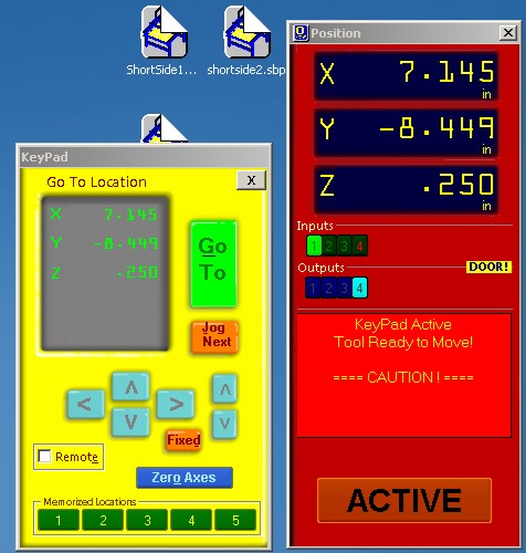
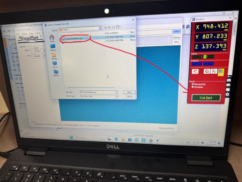
- Open the ShopBot software on your computer
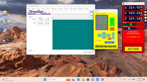
- Define your X/Y, inspired by our work in week 4. select the button that looks like a miniature version of the yellow keyboard. Use the arrow buttons on the keyboard to set the bit to match the XY reference position defined in the file configuration options.
- Here, to define the Z, place the sensor under the tool as shown in the following image
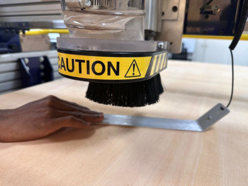
-
In the software, select your file, then click on Cut Part.
-
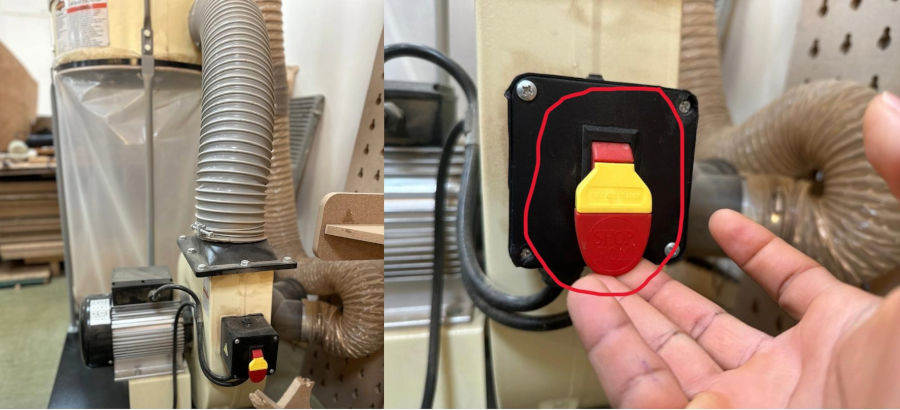
Activate the tool by pressing the button circled in red
- Activate the depourser by lifting the crank as shown in the image below.
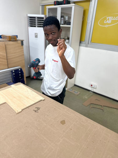
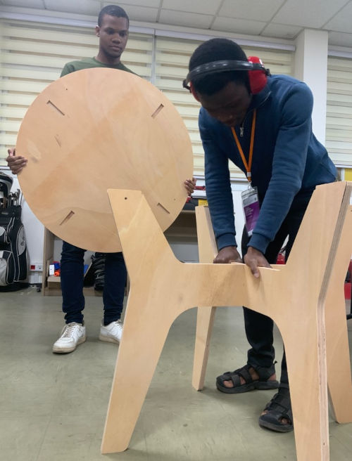
- Take off your different shapes

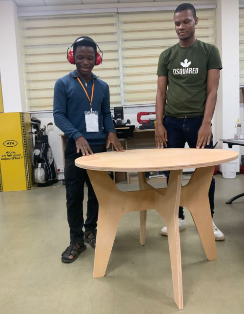
Well done! We made a wonderful table
Project files
Links
- https://tufts.makernetwork.org/equipment/shopbot-desktop-cnc-router
End