8. Electronic design
Group assignment :
-
Use your laboratory test equipment to observe the operation of a microcontroller PCB
-
Send a PCB to a board of directors
To see our group assignment click here
Individual assignment:
- Use an EDA tool to design a development board to interact and communicate with an embedded microcontroller, produce and test it
- Extra credit: try another design workflow
- Extra credit: design a package for it
- Extra credit: simulate its operation
Eagle
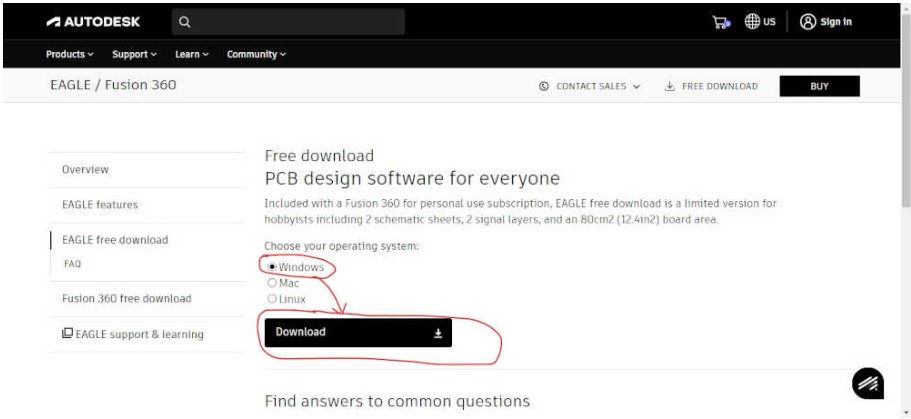
To download Autodesk Eagle click here Once on the site select the Windows option and click on Download.
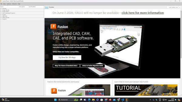
After installing the Eagle software on your desktop or in the folder of your choice, open it and you should see the following:
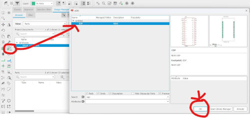
- Click on File > New > Schematic

- Click on the Add Part button and select the required component
- Add the following components to the reserved space and use the Net tool to connect the various components
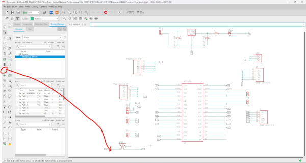
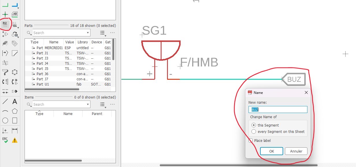
- Click on Name and rename the green lines as shown below.
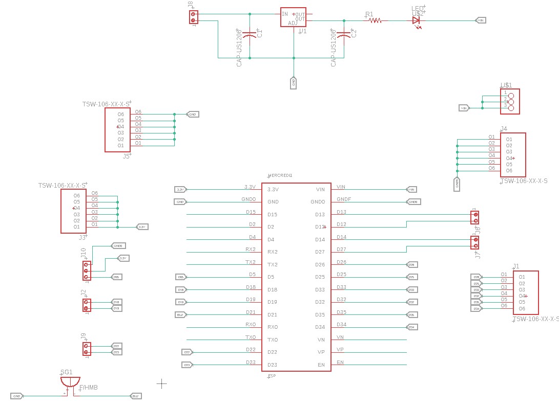
- When you finish, you should have a correct schematic with all links well defined
We have finished the drawing of the electronic schematic and now we will draw the PCB.
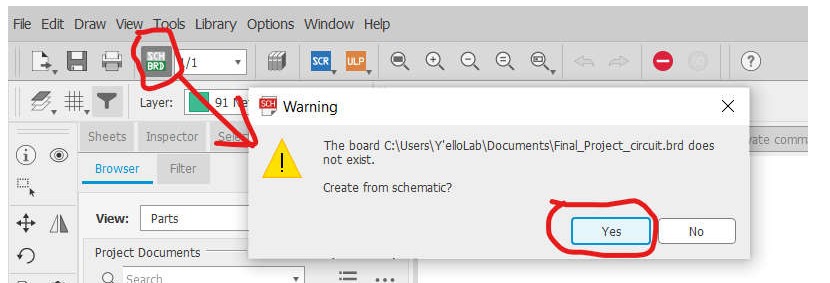
- Click on the Generate/switch to bord button and click on Yes you should have the following display.
-
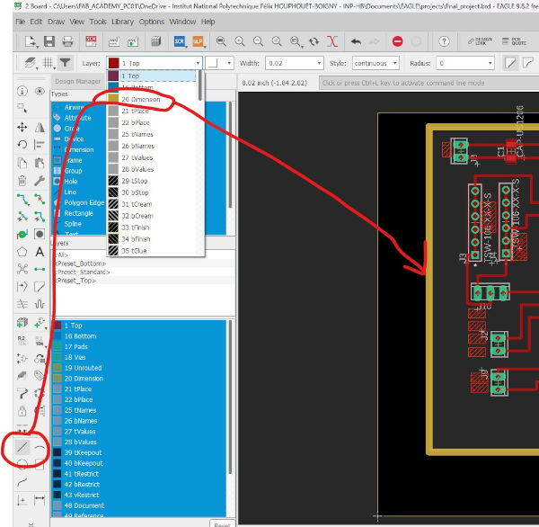
place your elements in the black area that appears
-
For connection, use the Route airwire
We have chosen a Widht = 0.02 inch

- To draw contours, choose : Line > in Layer, Dimension and draw the contour of your choice
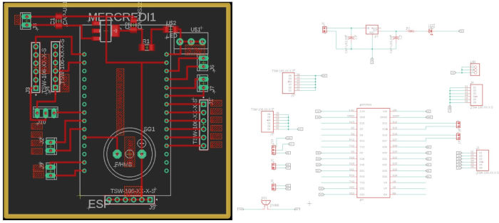
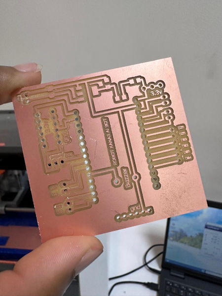
Here is our electronic schematic and our PCB after we finished our design.
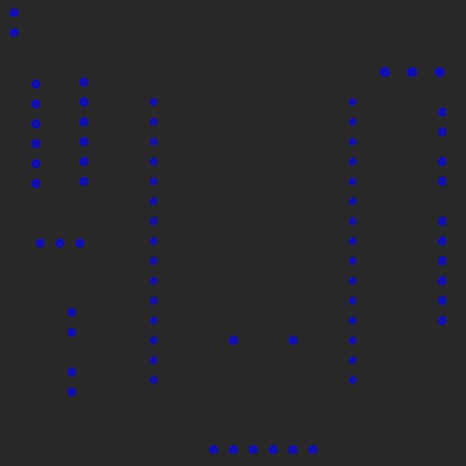
Generation of PNG files for the traces and the board outline
Once I have all the components placed and the tracks together, I need to export the file as a .PNG. But first we need to be only exported the tracks, and after the outlines. To do this we followed the process below:
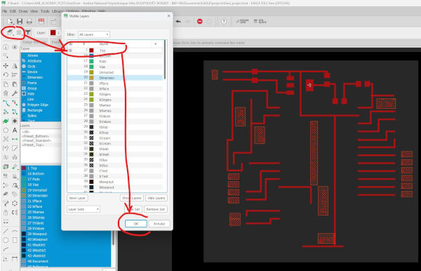
- Click on Layer Settings, go to Filter select Used Layers and uncheck all but Top and click on OK.
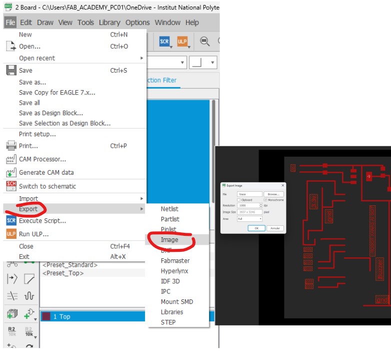
- Go to File > Export and click on Image a window will open, click on Browse… to choose the file type and location, select Monochrome with Resolution = 1000 dpi and click on OK.
- Repeat the same procedure as above and in layer settings select Dimension instead of Top. You should have the results below.
Click here to download the PNG files.
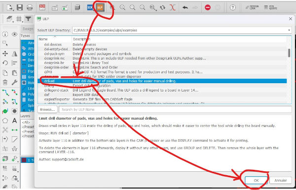
For drilling holes, click on Run ULP
Electronic card production
For the generation of the tool path, use our work from the week 4 as a guide
ok!! So if you have followed the steps shown in week 4, you get the following
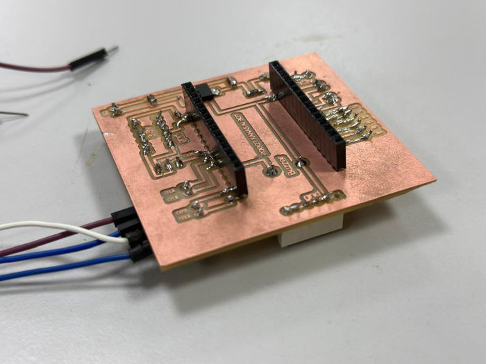
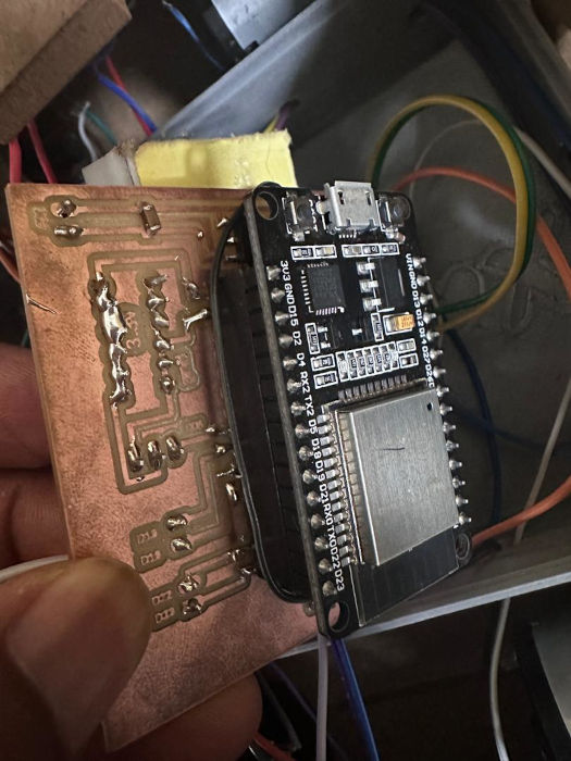
- we solder on the board the connectors to receive the development board. We’ve connected a buzzer to the circuit
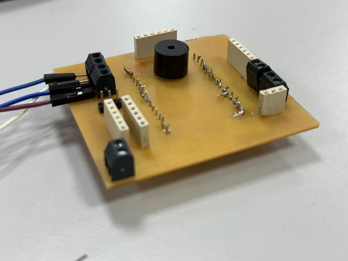
List of components
| Components | Qté |
|---|---|
| buzzer | 1 |
| Led smd | 1 |
| Resistor smd | 1 |
| Capacitor smd | 2 |
| screw connector | - |
| female connector | - |
| male connector | - |
Files
END