13. Networking and communications
Group assignment:
- Send a message between two projects
To see our group assignment click here
Individual assignment:
- Design, build and connect wired and wireless nodes with network or bus addresses and a local interface
For this week’s assignment, we’ll be communicating the board we designed in week 4 with an arduino nano board to perform different types of communication. We’ll be using the SPI, I2C and MQTT protocols respectively.
SPI protocol
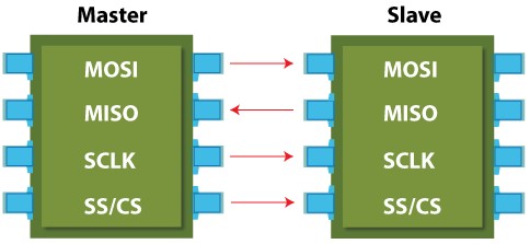
SPI (Serial Peripheral Interface) is a synchronous communication protocol used to transfer data between electronic devices, usually on a printed circuit board or between several boards.
SPI generally uses four wires for communication:
- MOSI (Master Out Slave In): Data line from master to slave.
- MISO (Master In Slave Out): Data line from slave to master.
- SCLK (Serial Clock): Clock synchronizing data transmission.
- SS (Slave Select): Line used to select the slave with which the master communicates.
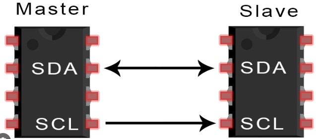
SPI protocol schematic diagram
The figure below shows a simplified schematic diagram of an SPI data link, with its main components.
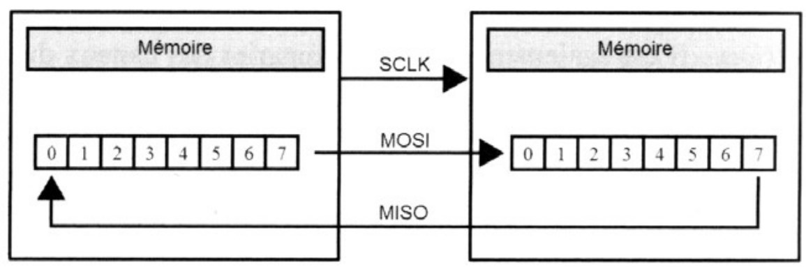
Two shift registers are generally used, either hardware or software, depending on the devices used. For example, the RasP implements its shift register in software, while the MCP3008 uses a hardware shift register.
Example use of SPI protocol
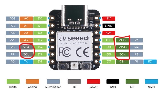
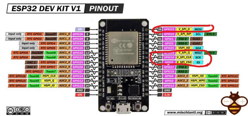
In this example, we’ll use the SPI protocol to communicate with a xiao rp2040 and a nano.
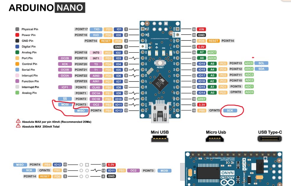
In the following images, we can see the pins that will help us circled in red.
To establish SPI communication between an ESP32 and an Arduino Nano, follow these steps:
XIAO RP2040 side (SPI master):
-
Connect the SPI pins on the XIAO RP2040 (MOSI, MISO, SCK, and SS) to the corresponding ones on the Arduino Nano.
-
Make sure that the voltages used are compatible between the two devices (5V for the Arduino Nano and 3.3V for the XIAO RP2040).
-
Initialize SPI communication on the XIAO RP2040 as master.
-
Write the code to send data via SPI.
Arduino Nano side (SPI slave):
-
Connect the SPI pins on the Arduino Nano (MISO, MOSI, SCK, and SS) to the corresponding pins on the XIAO RP2040.
-
Make sure that the voltages used are compatible between the two devices.
-
Initialize SPI communication on the Arduino Nano as a slave.
-
Write the code to receive data via SPI.
Here’s an example of the code for each side:
Code for XIAO RP2040 (SPI Master) :
import machine
import time

# Configuration des broches SPI
spi = machine.SPI(0, baudrate=1000000, polarity=0, phase=0, sck=machine.Pin(2), mosi=machine.Pin(3), miso=machine.Pin(4))
ss = machine.Pin(5, machine.Pin.OUT)

# Fonction pour envoyer des données via SPI
def send_spi(data):
    ss.value(0) # Activer la ligne SS
    spi.write(bytes([data])) # Envoyer les données
    ss.value(1) # Désactiver la ligne SS

# Exemple d'utilisation
while True:
    send_spi(0xAA) # Envoyer des données (par exemple, 0xAA)
    time.sleep(1)
Code for Arduino Nano (SPI slave) :
#include <SPI.h>

volatile byte receivedByte;

void setup() {
  Serial.begin(9600);
  pinMode(MISO, OUTPUT); // Configurer MISO comme sortie
  SPCR |= _BV(SPE); // Activer SPI en mode esclave
  SPI.attachInterrupt(); // Activer l'interruption SPI
}

ISR(SPI_STC_vect) {
  receivedByte = SPDR; // Lire le registre de données SPI
}

void loop() {
  if (receivedByte != 0) {
    Serial.print("Reçu : ");
    Serial.println(receivedByte, HEX);
    receivedByte = 0;
  }
}
#include <SPI.h>

const int SS_PIN = 5; // GPIO5 pour SS

void setup() {
  Serial.begin(115200);
  SPI.begin(); // Initialize the SPI library
  pinMode(SS_PIN, OUTPUT);
  digitalWrite(SS_PIN, HIGH); // Désactive le périphérique esclave
}

void loop() {
  digitalWrite(SS_PIN, LOW); // Active le périphérique esclave
  SPI.transfer(0x42); // Envoie un octet
  digitalWrite(SS_PIN, HIGH); // Désactive le périphérique esclave

  delay(1000); // Attendre une seconde avant le prochain envoi
}
-
MISO: Connect MISO from ESP32 to MISO from Arduino Nano
-
MOSI: Connect ESP32 MOSI to Arduino Nano MOSI
-
SCK: Connect SCK from ESP32 to SCK from Arduino Nano
-
SS: Connect a digital pin on the ESP32 to SS on the Arduino Nano (e.g. GPIO5 on the ESP32 to D10 on the Arduino Nano).
In addition, be sure to connect the grounds (GND) of the ESP32 and the Arduino Nano together.
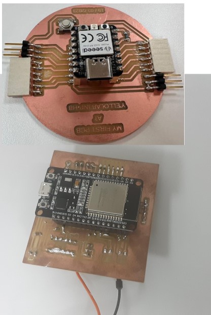
we have circled in red the pins useful for using this protocol
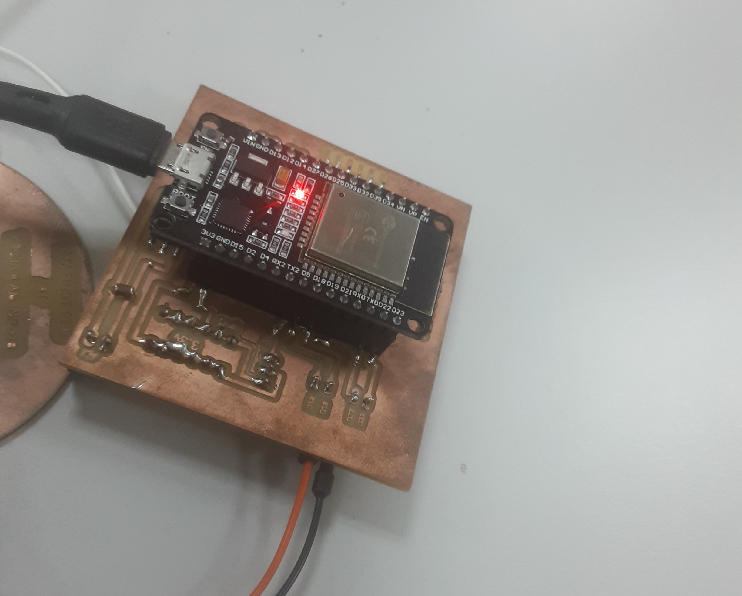
card circuit
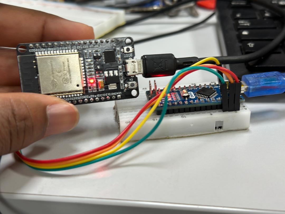
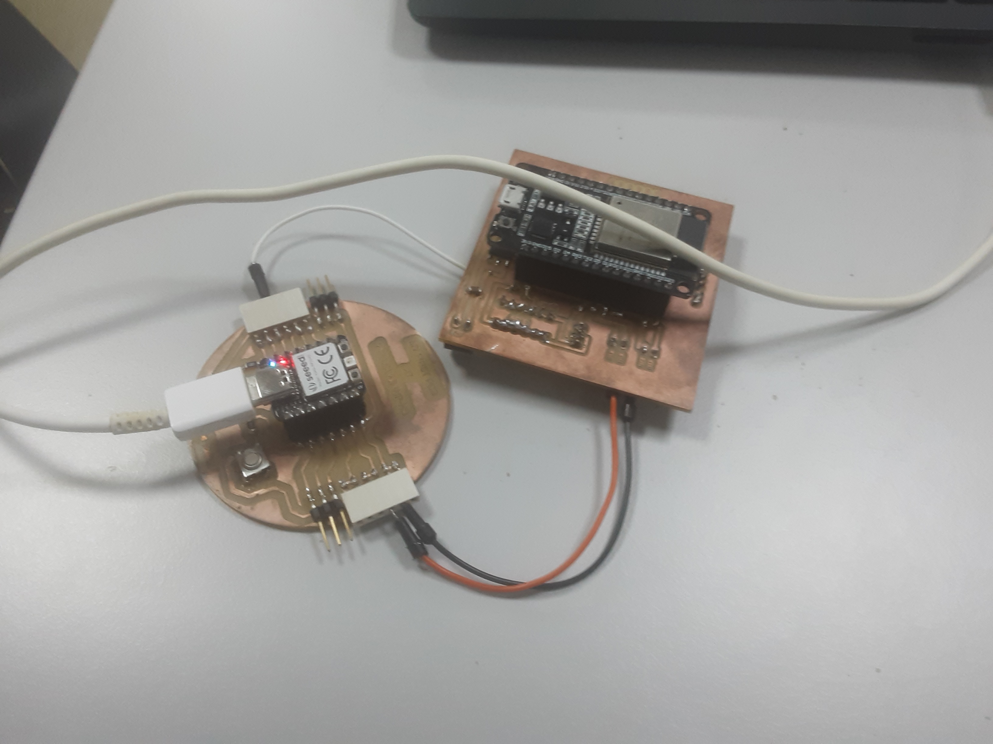
spi protocol cabling
-
The esp32 periodically sends data via SPI.
-
The Arduino Nano is configured as an SPI slave and reads the data sent by the esp32.
Use the cable for the Naono and a type B cable for the esp32.
SPI protocol project Code
I2C protocol
The I2C (Inter-Integrated Circuit) protocol is a synchronous serial communication protocol that enables several electronic devices to communicate with each other over a single two-wire data bus. It was developed by Philips (now NXP Semiconductors) in the 1980s.
The I2C bus uses two communication lines:
-
SDA (Serial Data Line): This line is used for bidirectional data transmission between connected devices. Data is transmitted serially on this line.
-
SCL (Serial Clock Line): This line is used to synchronize communication between devices. The signal on this line tells the peripherals when to read or write data on the SDA line.

The important features of the I2C protocol are as follows
-
Master/Slave: The I2C bus uses a master/slave scheme, where a master device controls the bus and initiates transactions, while slave devices respond to commands from the master.
-
Device addresses: Each device connected to the I2C bus has a unique address, usually 7 bits long. This address is used by the master to select the device with which it wishes to communicate.
-
Synchronous communication: Communication on the I2C bus is synchronous, meaning that it is synchronized by a common clock (the SCL line). Data is transmitted bit by bit, with the clock defining the transmission rate.
-
Start/Stop: Data transmission on the I2C bus begins with a start signal sent by the master, followed by the device address and transmission mode (read or write). The transaction ends with a stop signal.
Example use of I2C protocol
In this example, we will establish I2C communication between a XIAO RP2040 and an OLED display.
Oled pinout
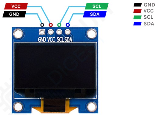
Hardware connection
-
Connect the SDA (Data) pin of the XIAO RP2040 to the SDA pin of the OLED display.
-
Connect the SCL (Clock) pin of the XIAO RP2040 to the SCL pin of the OLED display.
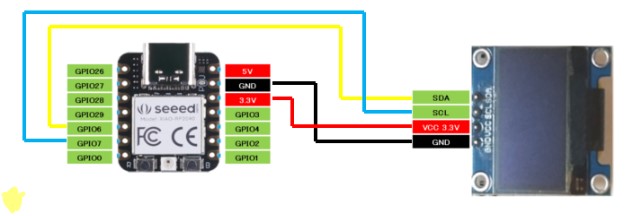
-
Make sure that the voltages used are compatible between the two devices (3.3V for the XIAO RP2040 and 3.3V or 5V for the OLED display, depending on your display’s specifications).
the following diagram will help you
Download the following code
from ssd1306 import SSD1306_I2C
from machine import Pin, I2C
from time import sleep
i2c = I2C(1, scl=Pin(7), sda=Pin(6), freq=200000)#Grove - OLED Display 0.96" (SSD1315)
oled = SSD1306_I2C(128, 64, i2c)
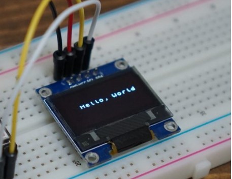
while True:
oled.fill(0)#clear
oled.text("Hello, world")
oled.show()
#sleep(0.5)
I2C protocol project Code
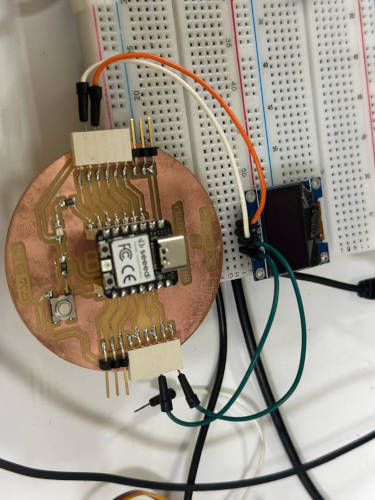
Still using the I2C protocol, we used our xiao board and our board for the final project.
To establish I2C communication between a Seeeduino XIAO (as master) and an ESP32 (as slave), we’ll use Arduino’s Wire library.
here are the different codes
Code for Seeeduino XIAO (Master)
#include <Wire.h>

void setup() {
  Wire.begin(); // Initialiser I2C en tant que maître
  Serial.begin(9600);
}

void loop() {
  Wire.beginTransmission(0x08); // Adresse de l'esclave ESP32
  const char* msg = "Hello ESP32";
  Wire.write((const uint8_t*)msg, strlen(msg)); // Envoyer des données
  Wire.endTransmission();

  delay(1000); // Attendre 1 seconde

  Wire.requestFrom(0x08, 10); // Demander 10 octets à l'esclave ESP32

  while (Wire.available()) {
    char c = Wire.read(); // Lire un octet
    Serial.print(c); // Afficher les données lues
  }
  Serial.println();

  delay(1000); // Attendre 1 seconde
}
#include <Wire.h>

void setup() {
  Wire.begin(0x08); // Initialiser I2C avec l'adresse de l'esclave
  Wire.onReceive(receiveEvent); // Registre la fonction de réception
  Wire.onRequest(requestEvent); // Registre la fonction de demande
  Serial.begin(9600);
}

void loop() {
  delay(100);
}

void receiveEvent(int howMany) {
  while (Wire.available()) {
    char c = Wire.read(); // Lire un octet
    Serial.print(c); // Afficher les données reçues
  }
  Serial.println();
}

void requestEvent() {
  const char* response = "Hello XIAO";
  Wire.write((const uint8_t*)response, strlen(response)); // Envoyer des données au maître
}
Connections
To connect the two devices :
-
Connect SDA from XIAO to SDA from ESP32.
-
Connect SCL from XIAO to SCL from ESP32.
-
Connect XIAO GND to ESP32 GND.
END