4. Electronics production
Group assignment:
-
Characterize the design rules for your in-house PCB production process: document feeds, speeds, plunge rate, depth of cut (traces and outline) and tooling.
-
extra credit: send a PCB out to a board house
-
Document your work to the group work page and reflect on your individual page what you learned
To see our group assignment click here
Individual assignment:
-
Make and test the development board that you designed to interact and communicate with an embedded microcontroller
-
extra credit: make it with another process
this is the fourth week of the Fab academy. This week we’re asked to build an electronic circuit. To do this, we’re going to use the monofab SRM-20 available in our Fab lab.
The monofab SRM-20
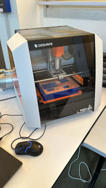
The Monofab SRM-20 is a desktop digital milling machine manufactured by Roland DG Corporation. This machine is designed for rapid, precise manufacture of prototypes, models and small parts, using a variety of materials such as wood, plastic, wax and certain non-ferrous metals.
- download the PNG files.
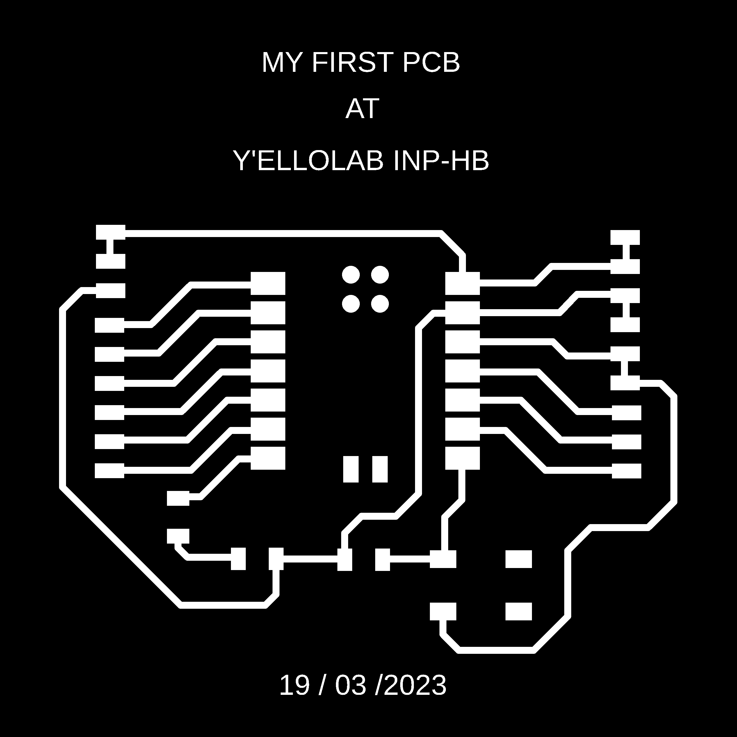
we’ll use a typon model to build our electronic circuit. Click on download to obtain the model. Ce modèle est celui de William AMANY

- The tool path
Toolpath generation is a crucial step in the PCB manufacturing process. This step consists in defining the path that the manufacturing tool (usually a milling cutter or drill) must follow to remove excess copper and create the necessary tracks and holes according to the circuit diagram. You can use the following software to generate your toolpath : Vcarve, FlatCam, mods CE . . .
Once the toolpath has been generated and verified, you can start the PCB manufacturing process, using a suitable CNC machine to perform the milling and drilling operations according to the instructions provided by the toolpath.
This week, we’ll be using CE mods to generate our toolpath, as it’s an open source solution and compatible with the tools we have at the Fab Lab.
- Using the CE mods
For more information on the use of mods, please consult the following linkmods CE
-
Access the mods by clicking on the CE mods link.
-
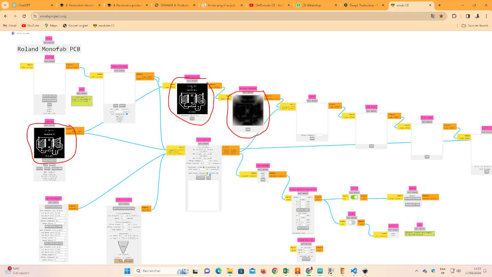
Once on the CE mods page, right-click your mouse in the white area as shown below. Select programs> open program> SRM-20 grinder> PCB, and you should see the display below.
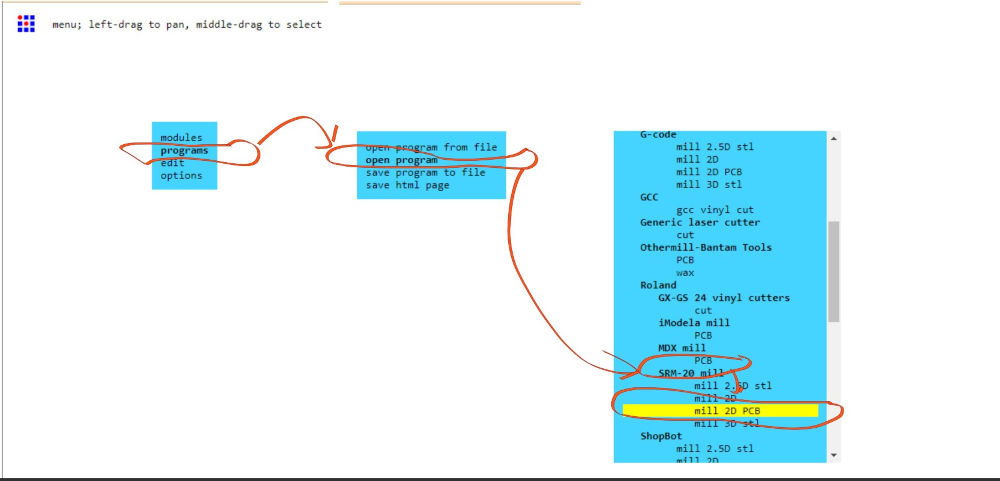
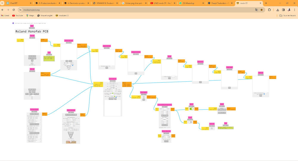
If you have followed correctly, this will appear on your screen👇👇
- Go to the read png module and click on select png file, select the track png file as shown below and click on open.
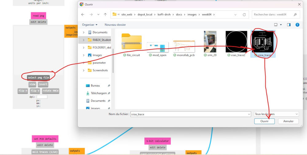 👇👇👇👇👇👇👇👇👇👇👇👇👇👇👇👇👇👇
- Mods setup for G-code generation for Roland SMR-20 milling machine
to set parameters, follow this path. go to define pcb default parameters > milling paths (1/64) (to choose tool cutting parameters). then go to the Roland SRM-20 milling machine module. Enter the value 0 for each axis coordinate reference (0,0,0). Set jog height to 12**

- Genarate the G-code
To generate the G-code, don’t worry, it’s not very complicated
- Go to the ON/OFF module and set the slide to ON, then go to the mill raster 2D module and click on Calculate.
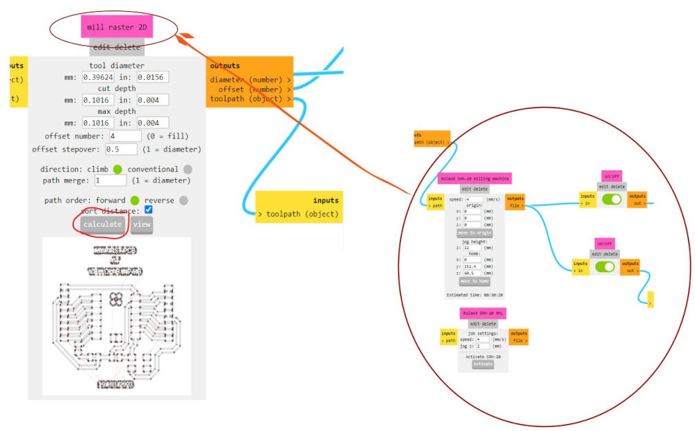
The result is below 👇

- click again on select file png and import the file for cutting the plate.

This time click on Invert to tell the machine it’s a cut-out

Follow the same procedure as above, but in the define pcb default parameters module, choose the milling paths (1/32).

Now that we’ve finished generating the G-codes for the toolpaths, let’s move on to the machining of our electronic circuit.
Electronic circuit
Don’t worry, the Fab academy has produced a tutorial for making circuits with the monofab srm-20. You can view the tutorial by clicking on the following linkLink
Step 1 : On the machine
- On the computer connected to the machine, open the VPanel for SRM-20. warm up the spindle for 10 minutes at half speed before use. move the Spindle Spend module gauge to the middle, click ON in Spindle and wait another 10 minutes. After 10 minutes click on OFF
yes, it’s not easy to wait, but you have to 🤭🤭🤭.

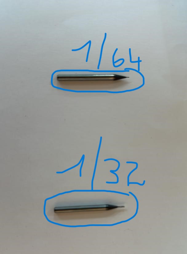
Step 2 : Choose your tools
To build our electronic circuit, we’ll be using two types of tool: the 1/64 track tool and the 1/32 copper plate cutting tool, as shown in the image below.
Step 3 : Place tool
Placing the tool is not very complicated.
-
Take the tool
-
Place it in the hole of the milling machine
-
grasp the tool, pull it slightly towards you and tighten the tool
Step 4 : Axis X, Y and Z
- Use touchs Y-, Y+, X-, X+ to move along the X and Y axes to an origin position of your choice.
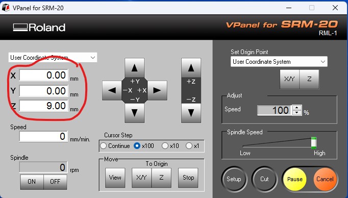
- Après avoir choisi votre point d’origine grace au boutons X/Z, dirigez-vous vers Set Origin Point > User Coordinate System then click on X/Z then click on Yes

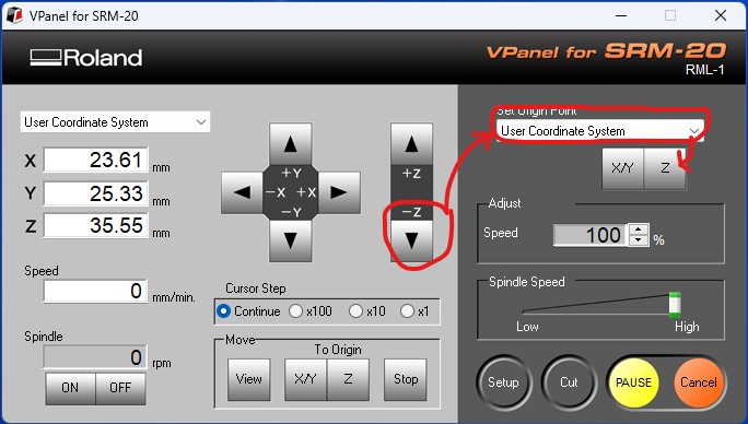
Pour l’origine Z
- Utilisez les touches Z- et Z+ jusqu’à ce que vous soyez prêt de la plaque cuivrée, puis dirrigez-vous encore vers Set Origin Point > User Coordinate System then click on Z then click on Yes
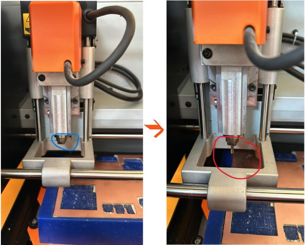
- Place the point of your tool right on the plate and tighten again

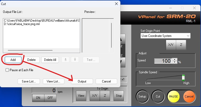
Step 5 : Import your file
- For import file, click on Cut > Add
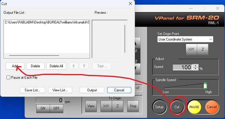
- choose your file and click on Output
Files sources
- Monofab project file : electronic circuit file
Video
You should obtain the following results

- Remove tool 1/64 and insert tool 1/32 to cut the plate

- Define a new origin for Z, select the file for cutting and click on Cut.
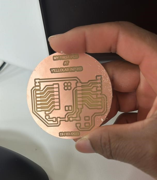
- ok, use a pair of pliers to remove your typon
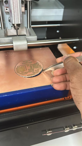
Tada! your typon is ready 🥳🥳🥳😎😎😎
List of Components
For our electronic circuit, we use :
| Name | Quantity | Price | Link |
|---|---|---|---|
| Xiao rp2040 | 1 | 4,68 000 $ | link |
| Resistor (1000k) | 2 | ||
| Micro LED SMD | 1 | ||
| push button | 1 | ||
| conn header SMD R/A 36 pos | 6 | 11,91 £ | link |
| BG300-06-A-LA | 2 | 0,51227 $ | link |
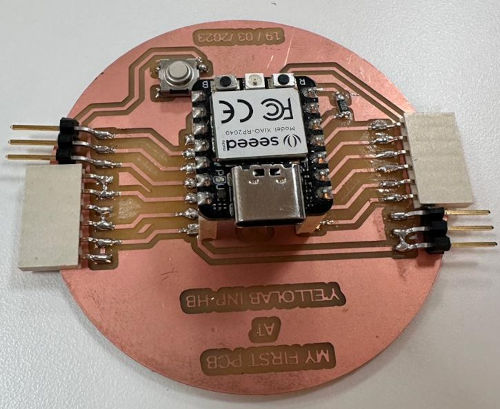
Result 01

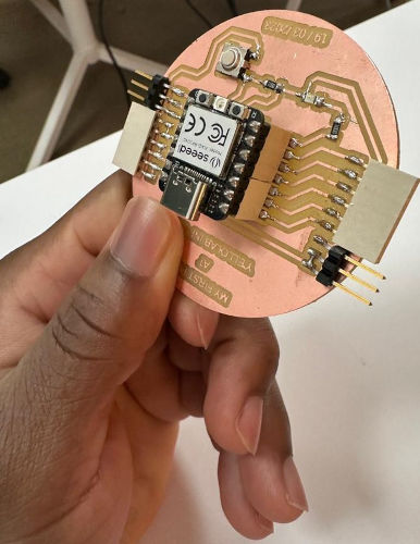
Result 02
Result 03
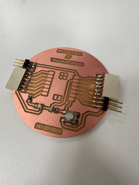
Tada!!! we’ve finished soldering our components, so our electronic circuit is ready!
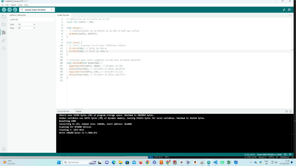
Code test
// Définition de la broche de la LED
const int ledPin = D10;

void setup() {
  // Initialisation de la broche de la LED en tant que sortie
  pinMode(ledPin, OUTPUT);
}

void loop() {
  // Faire clignoter la LED avec différents délais
  blinkLED(10); // Délai de 500 ms
  blinkLED(50); // Délai de 1000 ms
}

// Fonction pour faire clignoter la LED avec un délai spécifié
void blinkLED(int delayTime) {
  digitalWrite(ledPin, HIGH); // Allumer la LED
  delay(delayTime); // Attendre le délai spécifié
  digitalWrite(ledPin, LOW); // Éteindre la LED
  delay(delayTime); // Attendre le délai spécifié
}
Project file :
Result final
Our circuit enables us to light an LED as shown below

Below are some links to PCB manufacturers who can help you build your boards.
End