3. Computer controlled cutting
Group assignment:
- Characterize your laser cutter’s focus, power, speed, rate, kerf, and joint clearance.
To see our group assignment click here
Individual assignments:
-
Design, lasercut, and document a parametric press-fit construction kit, which can be assembled in multiple ways. Account for the laser cutter kerf.
-
Cut something on the vinyl cutter.
EPILOG FUSION edge 12
Parametric design 
Step.1 Modeling
Parametric design is an operating mode of today’s computer-aided design software. It involves defining an entity by parameters that can be easily modified. In this way, you can easily change the definition of the part. To do this we will use Fusion 360. Without delay :
- Open Fusion 360
- Create a new sketch
- Go to the parameters window : In the designe space > Modify > Modify parameters
see the picture below
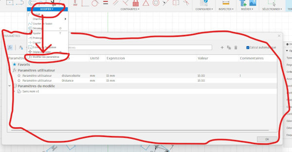
- To create new parameters, click on + User parameters and fill in the fields as shown below. To create a new parameter, click on + and fill in the fields that will appear. The parameters we have defined are shown in the following image

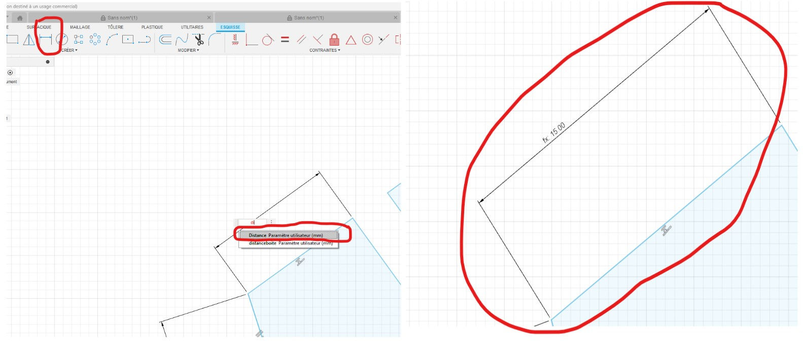
- To apply this parameter to a distance, nothing could be simpler. Click on the red tool and click on the segment to be measured. This time, instead of defining a distance, type in the information bar the variable distance defined as parameter
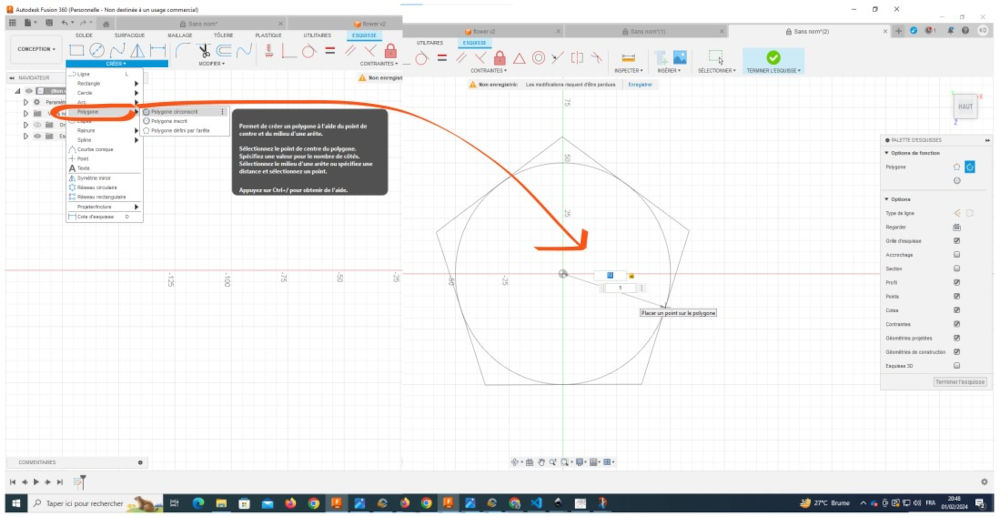
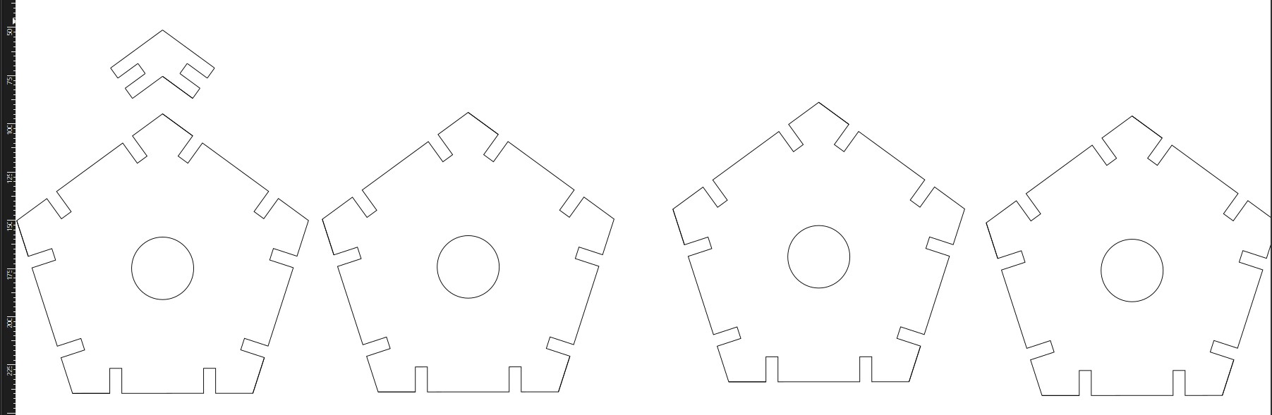
- In the create tab, select polygon and circumscribed polygon. on your drawing area, draw your polygon with a 50 mm radius. see the picture below.
- Then make a notch as shown below
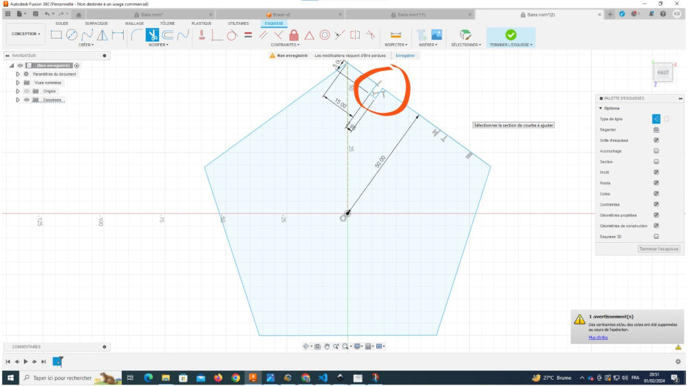
- Reproduce this notch with the Symmetry tool to the vertices of your polygon as shown below
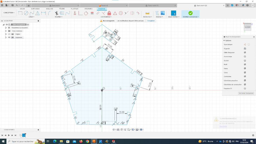
- Using the Line and Symmetry tools used higher, sketch the shape below.

To link our polygons together
- you can copy and paste your shapes ( 7 for polygoness and 21 for links)
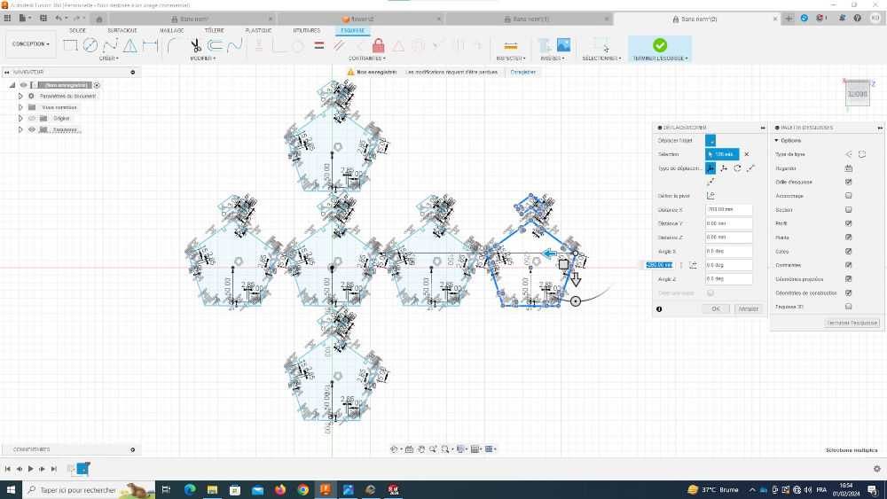
- when done, click Finish to exit sketch mode.

- Select your shapes and use the Extruder tool to add thickness.

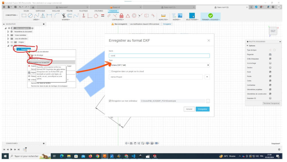
- Export your file in DXF format by: File > Export
DXF, which stands for Drawing eXchange Format, is a format used to exchange CAD files between CAD systems that do not use the same native file format.
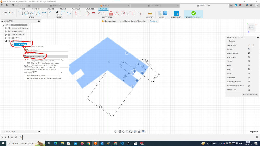
- Save your model in a folder
Super!!!🥳🥳🥳, some of the work just finished but it’s not over yet, be patient we’ll suffer a little longer 😊🤭😊
Step.2 Under Inkscape
- open inkscape, move your mouse over : File > Import choose your file and open in Inkscape.

with the file imported, you should obtain the image below
In Inkscape, select your shapes and move the mouse to Background & Outline > Outline Style and enter a value of 0.2 mm for a finer cut.

You can also add a border in red or a color of your choice.
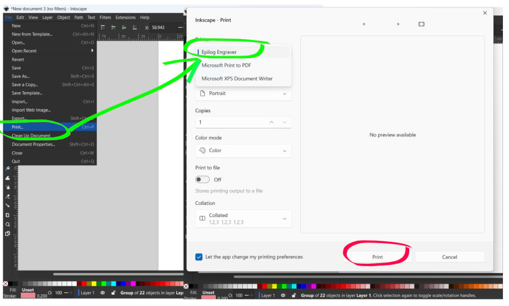
If you are satisfied with the result, click on File > Print and select Epilog Engraver
When you select Epilog Engraver, you click on Print for access to software of your machine.
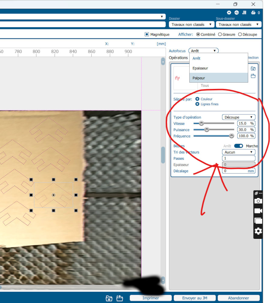
With the machine software, you place your shapes on the material you want to use to design your parametric kit. For us, we’ll use cardboard 5 mm. For laser cutting, please enter the following data :
- Type of operation: Cut
- Speed : 15 %
- Power : 30 %
- Frequency : 100 %
- Autofocus : Sensor
when are you finish, you clik on Print
Step.3 On the machine
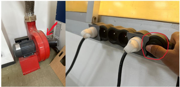
When you have finished setting up the cutting data, go to the machine and do :
- turn on the air compressor to avoid the risk of fire. The compressor is already plugged into the socket, just hold the on button on the socket to activate it.
- Place the material inside the machine and close.
- Select your file on the screen of machine

- Click on this button for begin the cutting

Well done, you’ve done it!!!! 👊💪

Now assemble your shapes and you’ll get this 👇👇👇
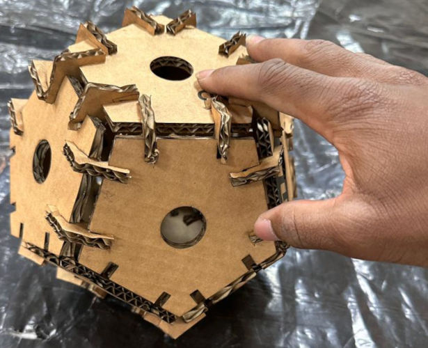
Isn’t it wonderful?
Vinyl cutting
In this tutorial, we’ll use the Roland GS-24 vinyl cutter to cut anything from. The GS-24 is a cutting plotter capable of producing various graphic elements thanks to a 58.4 cm cutting width. It’s ideal for creating banners, streamers, vehicle graphics, signs, point-of-purchase (POP) graphics, personalization, rear-projection materials, thermal transfer, stencils, and much more. The GS-24 offers greater stability and 40% more blade pressure
machine features
| Designation | Value |
|---|---|
| Maximum cutting zone | 584 mm (L) × 25 000 mm (L) |
| cutting speed | 10 - 850 mm/s |
| Blade force | 30 - 500gf |
| Mechanical resolution | 0,0125 mm/pas |
| Distance accuracy | Error less than ±0.2% of distance covered or ±0.1 mm (whichever is greater) |
| Power source | Dedicated mains adapter Input: 100-240 VAC 50/60 Hz Output: 24 VDC 2.7 A |
| Rated current | 1A |

we’re going to cut out a logo
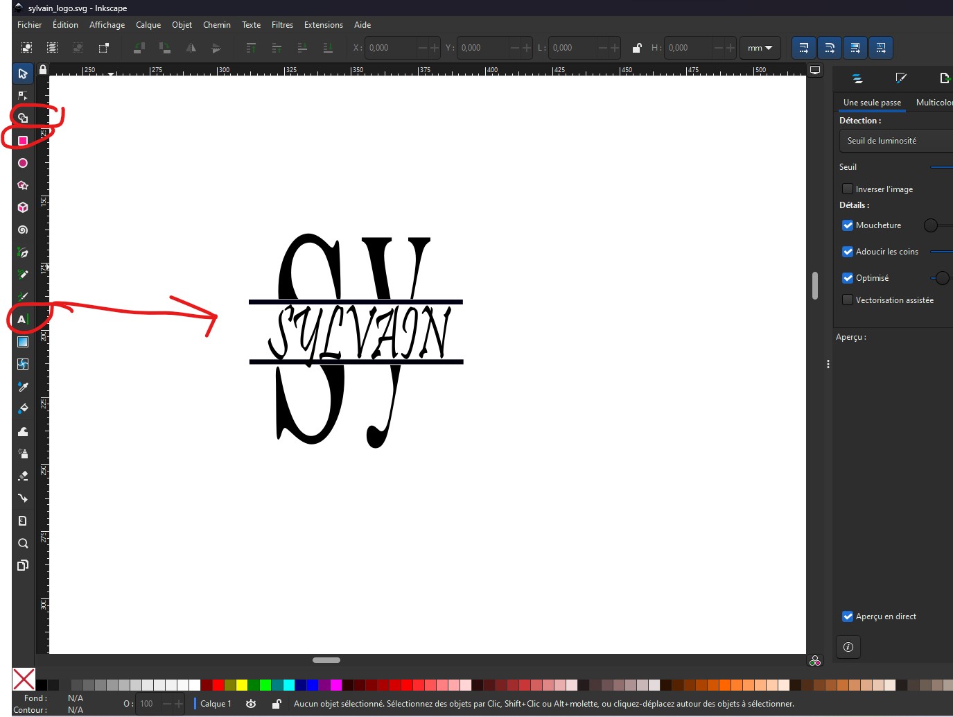
To do this, we’re going to use Inkscape again
- Open Inkscape and draw your logo on the design page using the tools Text tool, tool Rectangle, shape construction tool
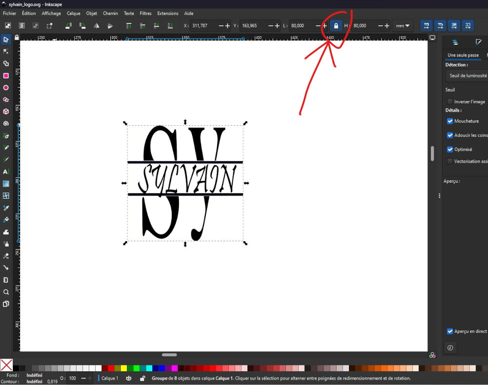
- Don’t forget to click on the padlock to block the dimensions of your logo
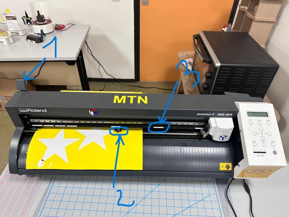
On the Vinyl cutter
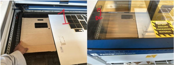
Push lever (1) to position the vinyl. Position the vinyl under the white stripes. Make sure the gallet (2) are in the area of the white stripes (3). Push back the lever after positioning the vinyl to hold the vinyl in place.
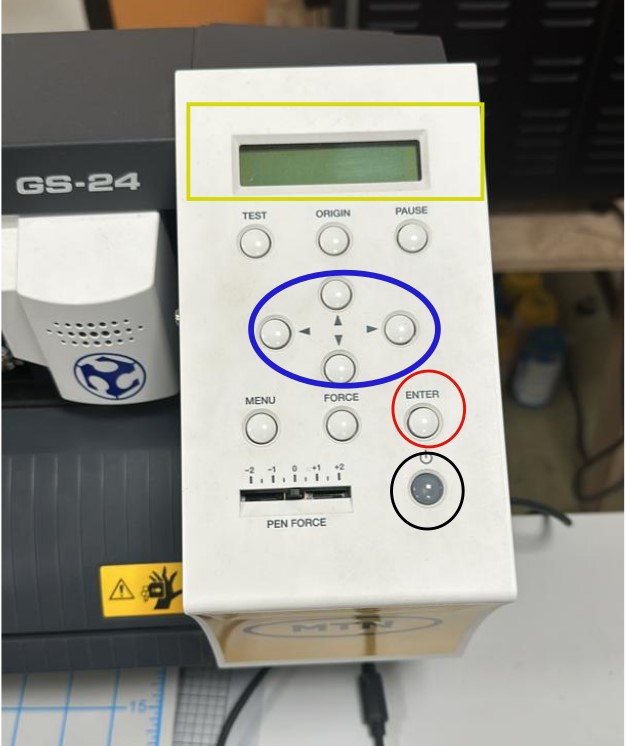
- Switch on the machine by holding down the button circled in Black
- Confirm by pressing the button circled in Red
- Observe the values on the yellow-framed screen
- Use the blue-circled buttons to set your origin point
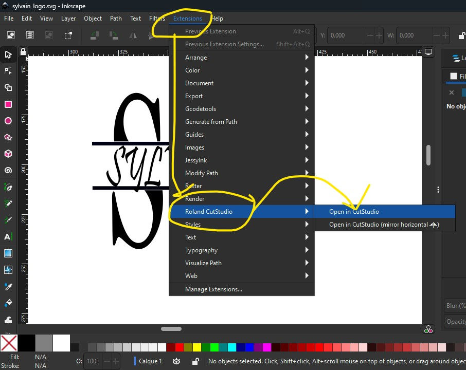
In Inkscape, do the following : Extensions > Roland CutStudio > Open in CutStudio*
When the CutStudio software is open and the pattern appears, click on Cutting entouiré in Blue.
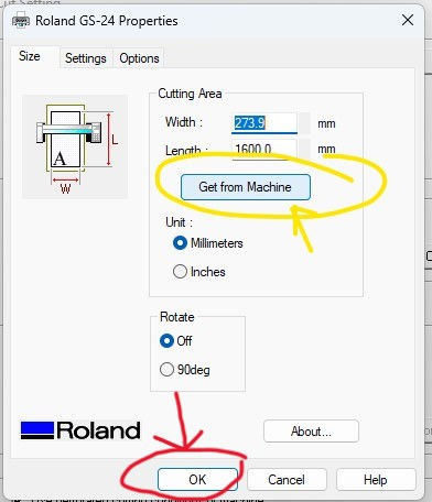
Click on Change
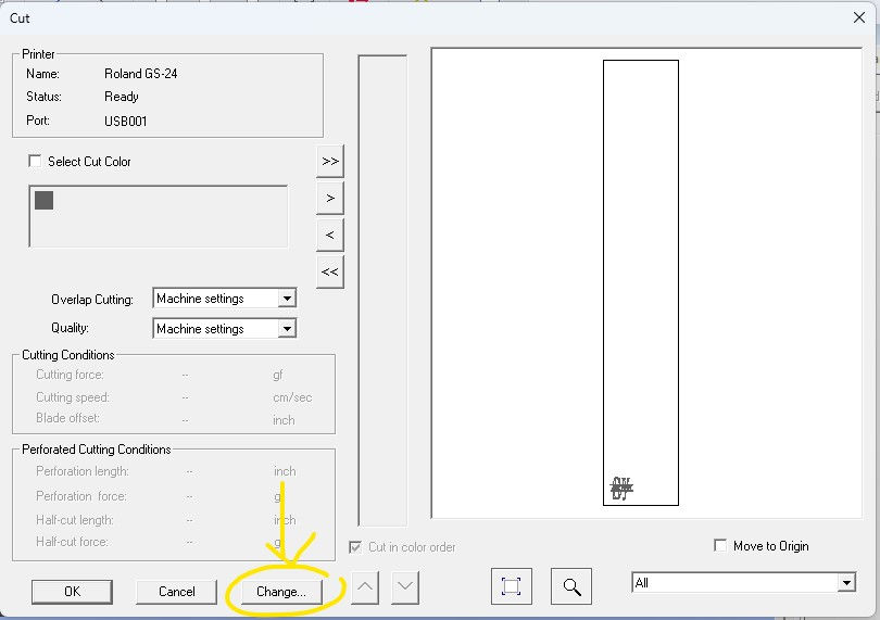
Click on Change

Click on Get from Machine and Ok
Ok guys, the most difficult part of this tuto has just been completed. You will see that your machine will cut your logo to the millimetre as you can see.

Admire the result

Links that may help you :
- Kone Zié Souleymane
- Jean-Nicaise AKAFFOU
- https://files.rolanddga.com/Files/GS-24_UsersManual/Responsive_HTML5/index.htm#t=GS-24_USE_EN_03_2.html
Project files :
End